1
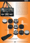
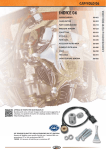
Form P6513
CCN 03530515
Edition 9
December 2006
Starter Relay Valve
SRV Series
User Manual
Save These Instructions
Product Description
This product is a non-regulating, pneumatically-operated, relay valve designed to provide control over fluid flow to the starter motor in an air
starter-based, internal combustion engine starting system.
WARNING
General Product Safety Information
•
•
•
•
Read and understand this manual before operating this product.
It is your responsibility to make this safety information available to others that will operate this product.
Failure to observe the following warnings could result in injury.
Always install, operate, inspect and maintain this product in accordance with all applicable standards and regulations (local, state,
country, federal, etc.).
WARNING
Product Safety Information
• This Starter Relay Valve is designed by Ingersoll Rand specifically for use on Air Starter installations. Any other use may result in injury or
equipment damage.
• Only use this Starter Relay Valve at or below 225 psig (15.5 bar/1550 kPa) maximum pressure, unless otherwise labeled. Higher pressure
may result in hazardous situations including rupture of the Starter Relay Valve and associated hardware.
• To use this Starter Relay Valve at a pressure of 225 psig (15.5 bar/1550 kPa), all associated pipe, hose and fittings must be rated at 225 psig
or more. Some IR models are sold with lower pressure ratings due to associated piping.
• Do not use this Starter Relay Valve with any corrosive gas or with any liquid.
• Except for SRV100, SRV125, SRV150 and SRV150SS, the Starter Relay Valve was designed for use with compressed air only. Only those
models may be used with natural gas.
• Always shut-off the air supply to the Starter Relay Valve, and bleed off any residual pressure, before performing any maintence on the
Starter Relay Valve.
• Never remove the Retaining Ring from the Starter Relay Valve unless all pressure has been bled off. Internal parts will be forcefully ejected
if Retaining Ring is removed while pressurized.
• Always wear eye protection when performing any maintenance on this Starter Relay Valve.
• Do not remove any labels. Replace any damaged label.
• Never use a damaged or malfunctioning Starter Relay Valve.
• Do not modify the Starter Relay Valve.
• Do not use this Starter Relay Valve for purposes other than those recommended.
• Be sure all hoses & fittings are the correct size & are tightly secured.
• Do not use damaged, frayed or deteriorated air hoses & fittings.
Safety Symbol Identification
DO NOT USE WITH
NATURAL GAS OR OTHER
FLAMMABLE GASES
Read Manuals Before Operating Product
This warning applies to all Starter Relay Valves except SRV100,
SRV125, SRV150 and SRV150SS.
Safety Information - Explanation of Safety Signal Words
DANGER
Indicates an imminently hazardous situation which, if not avoided, will result in death or serious injury.
WARNING
Indicates a potentially hazardous situation which, if not avoided, could result in death or serious injury.
CAUTION
Indicates a potentially hazardous situation which, if not avoided, may result in minor or moderate injury or
property damage.
NOTICE
Indicates information or a company policy that relates directly or indirectly to the safety of personnel or
protection of property.
03530515_ed9
Product Parts Information
CAUTION
The use of other than genuine Ingersoll Rand replacement parts may result in safety hazards, decreased Starter Relay Valve
performance, and increased maintenance, and may invalidate all warranties.
Repairs should be made only by authorized trained personnel. Consult your nearest Ingersoll Rand Authorized Service Center.
Placing the Starter Relay Valve in Service
NOTICE
PILOT (ACTIVATION) OPERATION PORT
TO AIR STARTER MOTOR
AIR SUPPLY
TO AIR STARTER CONTROL
VALVE (IF APPLICABLE)
TYPICAL INSTALLATION
(Dwg. 45508561)
This Starter Relay Valve is specially designed and manufactured by Ingersoll Rand for use on Starter installations. Install it in
accordance with the following instructions.
Pre-Installation
1.
2.
3.
4.
5.
Clean the air line, O-ring groove and sealing surfaces to be sure they are free of foreign material.
Ensure that enough space is left for removal and service of this valve.
Ensure that the air line is suitably aligned and supported to avoid strained joints.
Do not over tighten the air line connections.
Starter Relay Valves that have a small drain hole above the “OUT” connection (including SRV125T, SRV150T, SRV150T-LT and SRV150SST-LT)
are to be installed with the drain hole down.
Installation of the Starter Relay Valve (threaded connections)
1. Use a short pipe nipple between the supply line and the Starter Relay Valve. The nipple should be the same size as the inlet of the Starter
Relay Valve.
2. Apply No. SMB-441 Ingersoll Rand Sealant to the male thread on the nipple, and install the nipple on the supply line. Tighten the
connection so that it is airtight.
3. Note that one of the tapped inlets on the Starter Relay Valve is marked “IN”. Thread this inlet onto the nipple and tighten the connection so
that it is airtight.
4. Apply Ingersoll Rand Sealant to the male threads on the air line that goes to the Starter, and thread this line into the tapped outlet on the
Starter Relay Valve that is marked “OUT”. Make certain the connection is airtight.
5. Attach the hose from the outlet side of a 3-way normally vented Control Valve to the small tapped hole in the top of the Starter Relay Valve.
Use Ingersoll Rand Sealant on the male thread.
Installation of the Starter Relay Valve (flange connections)
1.
2.
3.
4.
5.
6.
Place the O-ring supplied with the flange fitting into the groove on the Starter Relay Valve.
Mount the Starter Relay Valve to the tank using ST500-K166 Flange Assembly. The air flow arrow must point toward the starter.
Check the O-ring to see that it properly seated in the groove to prevent cutting.
Push the two clamp halves inward as far as they will go.
Tighten the four flange bolts in an alternating pattern to 35-45 ft-lbs (47-61Nm) torque.
Attach the air hose from the outlet side of a 3-way normally vented Control Valve to the small tapped hole in the top of the Starter Relay
Valve. Use SMB-441 Ingersoll Rand Sealant on the male thread.
03530515_ed9
Starter Relay Valve Exploded View
1
2
3
4
5
6
7
8
9
10
11
12
13
(Dwg. TPD1731)
03530515_ed9
Starter Relay Valve Parts List
Part Number
Item
1
Part Description
Aluminum Models
Valve Housing
SRV150SS
(Stainless Steel)
SRV150T-LT
(Low Temperature
Aluminum)
SRV150SST-LT
(Low Temperature
Stainless Steel)
SRV150SS-40
45504404
45504362
for SRV100 SRV100-40
-
-
-
for SRV125 SRV125-40
-
-
-
for SRV125F SRV125F-40
-
-
-
for SRV125T 04333639
-
-
-
for SRV150 SRV150-40
-
-
-
for SRV150T SRV150T-40
-
-
-
HSPPS-2
HSPPS-2
HSPPS-2
HSPPS-2
* SRV150-210
* SRV150-210
** 45504305
** 45504305
SRV150-246
04555900
45504388
45504289
** 45504321
** 45504321
2
Pipe Plug
3
Upper Piston O-ring
4
Piston
5
Bumper
* SRV150-339
* SRV150-339
6
Piston O-ring
* SRV150-211
* SRV150-211
** 45504313
** 45504313
7
O-ring Retainer
* SRV150-33
* SRV150-33
** SRV150-33
** SRV150-33
8
Spring
SRV150-250
SRV150-250
SRV150-250
SRV150-250
9
End Plug O-ring
* SRV150-67
* SRV150-67
** 45504347
** 45504347
10
End Plug
SRV150-338
SRV150SS-338
45504396
45504354
11
End Plug Seal O-ring
* SRV150-604
* SRV150-604
** 45504339
** 45504339
12
Retaining Ring
* SRV150-340
* SRV150-340
** SRV150-340
** SRV150-340
13
Pipe Plug
-
SRV150-368
-
SRV150-368
14
Warning Label “not for natural gas”
-
-
04333274
04333274
for SRV125F 04333274
-
-
-
for SRV125T 04333274
-
-
-
for SRV150T 04333274
-
-
-
* Indicates part in Tune-Up Kit SRV150-TK3
** Indicates part in Tune-Up Kit SRV150-LT-TK1
NOTICE
Tune-up Kits are available for maintaining the Starter Relay Valve. Those Tune-up Kits include all O-rings (3, 6, 9, 11), Bumper (5),
O-ring Retainer (7), End Plug Retaining Ring (12) and SRV-GR55 Grease.
03530515_ed9
Optional Equipment for SRV125F
M
L
U
U
J
A
K
B
P
Q
C
G
Q
N
R
P
O
F
T
H
S
I
E
D
(Dwg. TP2212)
Item
Part Description
Part Number
Solenoid and Mounting Hardware - Position 1
A
Solenoid
12 Volt Pioneer Connections
Item
Part Description
Part Number
Pilot Port Hardware - Position 2
150BMP-A1051C
12 Volt, Wire Leads
150BMP-1051B
L
90° Elbow with Push to Lock
EL90-4M4DOT
M
90° Elbow with JIC 37°
EL90-4M437M
Left and Right Live Air Port hardware - Position 3 and 4
12 Volt, Wire Leads
150BMP-2451B
N
90° Elbow with Push to Lock
B
900 Elbow with Push to Lock
EL90-4M4DOT
O
T Connection with Push to Lock
EL90-4M4D0T
150TMP-MRT4M4
C
Solenoid Mounting Bracket
150TMP-2451
P
Schrader Valve
D
Solenoid Mounting Screw (2)
Y133-105C
Q
1/4” Pipe Plug
04333654
E
Solenoid Mounting Screw Washer (2)
Y117-110
R
T Fitting with 1/4” NPT
SRV125F-188
F
Solenoid Mounting Bracket Screw (2)
150TMP-128
+
Pressure Gauge
SRV125F-1064
HSPPS-2
Secondary Inlet Port Hardware - Position 5
G
Solenoid Mounting Bracket Washer (2)
H
90° Elbow with Push to Lock
EL90-4M4DOT
Y14-516C
S
Check Valve
I
Connection Hose
150 TMP-125
T
Plug
SRVI25F-34
J
90° Elbow with Push to Lock
EL90-4M4DOT
U
1-1/4” Flange Kit
ST500-K166
K
Connection Hose
ST400-1056
150TMP-125
(+) Items Not Shown
For Position Coding information refer to Drawing 10554749
WARNING
Always wear eye protection when performing maintenance on the Starter Relay Valve. Always bleed off the pressure before
performing any maintenance on the Starter Relay Valve.
03530515_ed9
Installation of the Tune-up Kit
Disassembly of the Starter Relay Valve
1. Bleed off the pressure.
2. Clamp the Relay Valve in a vise with the Retaining Ring (12) up.
3. Carefully remove the Retaining Ring. The End Plug (10) should spring out. If it does not, tap the Valve Housing (1) lightly with a soft hammer
until the End Plug springs out.
4. Remove the End Plug, Spring (8), and Piston Assembly (4).
5. Remove and discard all used O-rings and Bumper (5).
6. Clean all other parts in a clean, suitable cleaning solution in a well ventilated area.
Assembly of the Starter Relay Valve
1. Using O-ring lubricant, lubricate and install the new Piston O-ring (6) and the new Upper Piston O-ring (3) on the Piston.
NOTICE
The Upper Piston O-ring (3) is slightly larger in diameter than the End Plug O-ring (9).
2.
3.
4.
5.
6.
7.
8.
9.
Turn the Piston over and insert the new Bumper (5).
Using O-ring lubricant, lubricate and install the new End Plug Seal O-ring (11) and the new End Plug O-ring (9) on the End Plug (10).
Lubricate the lower small bore of the Valve Housing (1) with O-ring lubricant.
Insert the Piston Assembly into the Valve Housing. Push on the Piston until the Piston O-ring (6) seats against the beveled face.
Install the O-ring Retainer (7) with the large opening over the Piston O-ring.
Place the Piston Spring (8) on the Piston.
Place the End Plug Assembly on the Piston Spring.
Using a press to hold down the End Plug Assembly, install the End Plug Retaining Ring (12).
General Information
When the life of the Starter Relay Valve has expired, it is recommended that the Starter Relay Valve be disassembled, degreased and parts be
separated by material so that they can be recycled.
The original language of this manual is English.
Manuals can be downloaded from www.irtools.com.
Refer all communications to the nearest Ingersoll Rand office or distributor.
03530515_ed9
www.irtools.com
© 2006 Ingersoll Rand Company