1
P6567
03531480
Edition 13
January 2014
Starters
Series SS815, SS825 and SS850
Installation and Maintenance
Information
EN Installation and Maintenance Information
ZH 安装和维护信息
JA
据付および保守の情報
Save These Instructions
EN
Product Safety Information
Intended Use:
These air starters are intended for use in starting reciprocating internal combustion engines. These starters are designed to be
operated from a remote location after proper installation on the engine requiring starting.
For additional information refer to Air Starters for Internal Combustion Engines Product Safety Information Manual Form 45558624.
Manuals can be downloaded from ingersollrandproducts.com.
Placing Starter in Service
NOTICE
at a safe location and must not be interconnected with any other
exhaust lines which might introduce a back pressure on the drive
housing vent.
For natural gas operation, starter main exhaust must be piped
away.
To pipe the drive housing vent, remove the drive housing plug
and replace it with a suitable tubing line. The tubing must vent
Lubrication
Proper lubrication is essential for top performance and maximum
durability of a Starter.
Two lubrication systems are recommended:
Ingersoll Rand No. HDL2 Lubricator: For Starter installations with
cranking cycles of less than 10 seconds. Install as shown in
Dwg. TPB978. (See Installation of HDL2 Lubricator on EN-4).
Lubricate with diesel fuel or 10W non-detergent motor oil.
CAUTION
When an HDL2 Lubricator is used, make certain that the oil
supply line pressure is no greater than 5 psi. If there is pressure
on the line, the Lubricator will continuously leak lubricant
through the Starter and out of the exhaust.
Ingersoll Rand No. NL-24-8 In-Line Lubricator:
For Starter installations with cranking cycles more than 10 seconds.
Install as shown in Piping Diagrams. Lubricate with a good quality
10W non-detergent motor oil. Adjust the Lubricator to flow 1 to 3
drops per second.
Installation
NOTICE
For maximum performance, read this manual prior to the
installation or operation of Series SS815, SS825 and SS850
Starters.
General Information
1. We recommend that on all vehicular installations and on
stationary engines subject to vibration that hoses of the
specified diameter be used instead of rigid pipe connections to
the starter. Vehicle and engine vibration will soon loosen rigid
pipe connections, whereas hoses will absorb the vibration and
connections will remain tight.
2. This starter is designed for flange mounting at the inlet. All piping,
hoses and fittings must be clean and free of dirt and foreign
material during installation.
3. In the actual mounting of an Air Starter, it is best to have the hose
connections already made at the receiver, and to have the starter
end of the hose handy for attaching to the Starter.
4. Engine design often demands that the starter be mounted
underneath in extremely close quarters, and even though two of
the mounting bolt holes are easy to reach, the third one is often
less accessible. To install a starter, the following tools are required:
a regular ratchet wrench, sockets, universal joint, socket extension
and a single or double-end box wrench.
5. The efficiency of an Air Starter can be greatly impaired by an
improper hook-up. Hoses smaller than those recommended will
reduce the volume of air to the motor and the use of reducers
for piped-away applications in the exhaust port will restrict the
exhaust causing back pressure to the motor resulting in reduced
performance. The number of tees and elbows, and the length of
the supply line should be kept to a minimum. Use 1-1/2” #24 hose
or pipe for supply lines upto 15 feet long; use 2” hose or pipe if the
supply line is over 15 feet long.
6. A leak in any of the connections in live air lines means that the
system will drain overnight and will have to be re-pressurized
the next morning by use of another vehicle or compressor. Make
your connections bubble tight to avoid unnecessary costs and
delays. On all threaded connections throughout the system,
use Ingersoll Rand No. SMB-441 Sealant, non-hardening No. 2
Permatex or Loctite®* Pipe Sealant. Always run your air supply line
from the side or top of the receiver, never at or near the bottom.
Moisture in the air collects at the bottom of the receiver resulting
in damage which could cause the valves to become inoperative.
Periodically, open the petcock at the bottom of the tank to drain
the water.
* Registered trademark of Loctite Corporation.
03531480_ed13
EN
Orientation of the Air Starter
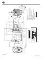
If the factory orientation will not fit your engine due to radial location
of the Drive Housing or location of the inlet and/or exhaust ports,
reorient the Starter as follows:
1. Look at the dimension illustration and note that the Drive
Housing (30) can be located in any one of sixteen radial positions
relative to the Gear Case (58). The exhaust port (Motor
Housing) (1) can be located in any one of four radial positions
relative to the Gear Case and the air inlet (Motor Housing Cover)
can be located in any one of four radial positions relative to the
exhaust port. Also, the Drive Housing can be installed on the
engine bell housing in any one of three radial positions.
NOTICE
Do not separate the Drive Housing from the Gear Case during
orientation or installation.
2. Study the engine mounting requirements and determine the
required orientation of the Drive Housing relative to the Gear
Case. If the Drive Housing has to be reoriented, remove the eight
Drive Housing Cap Screws (28) and rotate the drive housing to
its required position. Reinstall the Drive Housing Cap Screws and
tighten them to 28 ft-lb (38 Nm) of torque.
NOTICE
Do not separate the Motor Housing from the Motor Housing
Cover during orientation or installation.
3. Now that you have the Drive Housing properly oriented relative
to the Gear Case, notice whether or not the exhaust port will be
at the bottom and whether or not the inlet port will be favorably
located for hose installation. If either or both of these members
must be reoriented, remove the four Motor Housing Cover Cap
Screws (4) and rotate the Motor Housing and/or Motor Housing
Cover to its desired position. Reinstall the Motor Housing Cover
Cap Screws and alternately tighten them to 60 ft-lb (81.4 Nm) of
torque.
Mounting the Air Starter
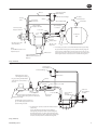
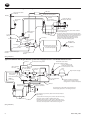
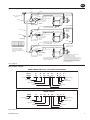
1. Study the Piping Diagram. We strongly recommend that the
Starter be connected exactly as shown.
2. The air receiver tank for a Starter installation must have a working
pressure capability equal to or greater than the maximum
pressure at which the Starter will be operated.
WARNING
Bleed off the air pressure through a valve or petcock. Do not
remove the plug from the tank while the tank is still pressurized.
3. If you are going to connect to a receiver tank that is already in
service, bleed off the air pressure by opening the drain valve.
Drain off any water that may have accumulated in the bottom of
the tank.
4. Using a 1-1/2” short nipple, install the SRV150 Starter Relay Valve on
the end of the receiver tank as shown in Dwg. TPC444-4 on EN-7.
5. Install the No. SMB-618 Starter Control Valve on the dash panel
(for vehicular installations) or some other appropriate panel (for
stationary installations).
6. Attach No. TA-STR-100 Starter Instruction Label to the control
panel adjacent to the Starter Control Valve.
7. Mount the No. 150BMP-1064 Air Pressure Gauge on or adjacent
to the control panel. It should be located where it is readily visible
to the operator of the Control Valve.
NOTICE
When connecting the Starter Control Valve to the Relay Valve,
make certain the hose is connected to the “SUMP” side of the
Starter Control Valve.
8. Connect the Starter Control Valve to the Relay Valve with 1/4”
#4 hose. Install a Tee in this line with a short feeder hose to the
Pressure Gauge.
9. Run a piece of heavy duty garden hose, or some other similar
large diameter hose from the Relay Valve on the receiver to the
starter location on the engine to determine the exact length of
1-1/2” #24 air hose required.
10.Attach the 1-1/2” #24 air hose to the outlet side of the Relay Valve,
and run the hose through the frame, etc. to its final position at
the starter location.
11.At this point, determine whether or not it is practical to attach the
hose to the Starter before or after the Starter is actually mounted.
In many cases, it may be necessary to attach the hose to the
Starter before mounting.
12.Liberally grease the teeth on the ring gear with a good, sticky
gear grease or motorcycle chain lubricant. This will help promote
the life of the ring gear and the Starter Pinion.
13. Place the Starter into position and mount it on the flywheel bell
housing. Tighten the mounting bolts to 100 ft-lb (136 Nm) of torque.
14.Install a 1/4” #4 hose line from the “DEL” side of the Starter Control
Valve to the “IN” port on the Starter Drive Housing.
15.Install a 1/4” #4 hose line from the “OUT” port on the Starter Drive
Housing to the small pipe tapped port on top of the Starter Relay
Valve.
16.If the exhaust is not to be piped away, install a No. SS660-A674
Muffler or No. SM450-A735 Road Splash Deflector in the exhaust
port on the Motor Housing of the Starter.
17.If the engine on which the Starter is mounted does not have a
bell housing with a standard starter mounting, and a bracket had
to be manufactured for mounting, we recommend that you add
an additional support bracket at the motor end of the Starter.
There are four holes in the Motor Housing Cover for this purpose.
They are tapped M10-1.50 to accommodate metric cap screws.
18.Mount an HDL2 Lubricator on or near the Starter as shown in
Dwg. TPB978 on EN-4.
19.Pressurize the complete starting system and check every
connection with a soap bubble test. There must be no leaks.
NOTICE
Make certain the connection between the SRV150 Starter Relay
Valve and the Receiver Tank is made to the inlet side of the Relay
Valve indicated by the word “IN” cast on the valve body.
03531480_ed13
EN
Barring Over the Engine
Occasionally, for setting injectors and/or for timing purposes, it may
be desirable to bar over the engine in such a manner that any given
piston can be stopped at any given location. This is very easily done
with a SS815, SS825 or SS850 Starter.
1. Disconnect the 1/4” #4 hose at the “OUT” port on the Drive
Housing, and plug the hole in the Drive Housing with a 1/4” pipe
plug.
2. Remove the 3/8” pipe plug from the center of the Motor Housing
Cover.
3. Engage the Drive Pinion with the flywheel by applying pressure to
the “IN” port on the Drive Housing.
4. Insert a 3/8” square drive wrench through the hole in the Motor
Housing Cover to engage the square drive recess the rear of the
Rotor.
5. Manually rotate the Rotor until the engine is cranked to its desired
position.
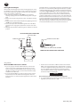
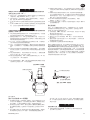
The HDL2 Lubricator is self-priming and may be installed directly on
the Starter or located remotely. Although the Lubricator is capable
of drawing lubricant from a source 4 ft (1.2 m) lower than the point
of installation, Ingersoll Rand recommends installing the Lubricator
as close as possible to the oil source. We recommend using the
unpressurized fuel return line as the source of lubricant. However,
oil may be supplied from a separate receiver or the diesel fuel tank.
When the diesel fuel tank is the lubricant source, install a 10 micron
to 50 micron fuel filter in the oil supply line at the fuel tank. The
lubricant supply line should be fed into the fuel return line with the
leg of the tee going to the lubricator directed in the down direction
to insure that the lubricator does not draw air instead of oil.
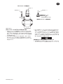
INSTALLATION OF HDL2 LUBRICATOR
AIR SUPPLY HOSE
LUBRICANT SUPPLY HOSE
LUBRICANT SUPPLY HOSE
TO STARTER AIR SUPPLY OR OIL CHAMBER
REMOTE INSTALLATION OF HDL2 LUBRICATOR
(Dwg. TPB978)
Mount the HDL2 Lubricator as follows:
1. If you are going to mount the HDL2 Lubricator on the Starter,
remove one of the 3/8” pipe plugs from the inlet boss on the
Starter and replace it with the HDL2. If you are going to mount
the HDL2 at a remote location, use two U-bolts and base clamp
available for the Lubricator.
2. If you mounted the HDL2 at a remote location, install a 1/4” #4
hose from the end of the Lubricator having both a male and
female thread to one of the 3/8” pipe tapped holes on the Starter
inlet boss.
3. Install a 1/4” hose from the 1/8” NPTF oil inlet in the side of the
HDL2 to the unpressurized fuel line, diesel fuel tank or separate
oil reservoir. Tighten the fitting at the Lubricator to 15 to 36 ft-lb
(20.3 to 40.8 Nm) torque. The threads on the fitting must be
clean; assemble it without sealing compound or Teflon®* tape.
Connection must be vacuum tight.
NOTICE
Before initial operation, manually fill the oil supply line.
4. If a separate lubrication reservoir is used, fill it with diesel fuel or a
light motor oil such as SAE 10 or 10W.
03531480_ed13
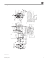
Ø 172.0
(Ø 172.0)
108.0
R 86.5 (4.3)
(3.4)
116.0
(4.6)
R 77.5
94.5
(3.1)
(3.7)
M10-1.5 Th'd .63 Deep
(16.0) 2-places
(For Rear Support)
Remove Pipe Plug for
Access to 3/8 Sq. Drive
Barring Hole in Rotor.
Cover
CL Inlet
434.0
(17.1)
322.0
(12.7)
1/4-18 Npt
Control Port
Inlet
159.5
(6.3)
CL
17.5 (.7)
Driving
Housing
23.0(.9)
1/4-18 Npt
Control Port
Outlet
138.5(5.5)
Orientation Options
2 1/2-8 NPT
Exhaust
Gear
Case
85.7
(3.4)
Ø152.0
(6.0)
CL
222.5(8.8)
10.0
(.4)
50.8
(2.0)
45.0
(1.8)
Pinion Travel
Pilot
1E
F
D
Control CL
Ports
Ring Gear Face
28.5
(1.1)
Ø 92.00
(3.6)
Vent Plug
SS825 Only
10.5(.4)
C
G
I
P
O
2
Ø 146.0
(5.7)
3
Right Hand
Rotation
Left Hand
Rotation
N
M
L
Ø 16.6 Typ.(0.6)
K 3-Places
CL Exhaust
A
J
CL Inlet
120° 0’
B
H
52º 30'
Ø
Inlet
4 @ 90º
Exhaust
4 @ 90º
mm
(Inch)
Dual
Dimensions
Notes:
1. Starters Should be Installed on the Engine With the
Exhaust Pointed Down.
2. Use the Set of Control Ports on the Upper Side of the
16 @ 22 1/2º
Drive Housing.
-MODEL CODING3. These Models are not Approved for Applications where
SS815 G B 03 R 31- 0 2 G
the Starter is Exposed to the Transmission Fluid.
4. Drive Housing Orientation Code is Based on Position Of
Drive Housing
Size Starter
Exhaust
Mounting Hole Opposite the Control Ports.
Type Starter
Orientation Code
Gearing
5. Standard Orientation Shown (02G) will be Shipped Unless
Inlet
Drive Housing
otherwise Specified.
Type Pinion
Rotation
6. Please Read the Instructions before attempting to
Drive
Reorient.
7. Starter Weight = 43.1 Kg (95 Lbs.)
447.7
(17.6)
C
L
Motor
Housing
Lubricator
Connection
Both Sides.
419.5
(16.5)
EN
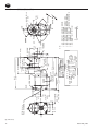
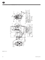
Mounting Dimensions for Series SS815 and SS825 Starters
(Dwg. TPA1325-1)
03531480_ed13
Ø 172.0
108.0
(4.3)
53.2
(2.1)
M10-1.5 Th'd
16.0 (.63) Deep 2-places
(For Rear Support)
R 48.7
(1.9)
R 43.6
(1.7)
65.2
(2.6)
Remove Pipe Plug for
Access to 3/8 Sq. Drive
Barring Hole in Rotor.
SS850
Inlet
G
Exhaust
4 @ 90º
Ø 110.2
(4.3)
168.0
(6.6)
Drive Housing
263.0
(10.4)
1/4-18 Npt
Control Port
Inlet
Drive Housing
Exhaust
Orientation Code
Inlet
Type Pinion
Drive
02E
16 @ 22 1/2º
Orientation Options
-MODEL CODINGB 09 R 51-
4 @ 90º
375.0
(14.8)
48.2
(1.9)
Gear
Case
2 1/2-8 NPT
Exhaust
Motor
Housing
Size Starter
Type Starter
Gearing
Drive Housing
Rotation
Cover
Lubricator
Connection
both Sides.
1 1/2 - 11 1/2 NPT
Inlet
361.5
(14.2)
28.5
(1.1)
18.0
(.7)
20.0
(.8)
186.5
(7.3)
Drive
Housing
1/4-18 NPT
Control Port
Outlet
10.7
(.4)
180.0
(7.1)
R 64.3
(2.5)
E
F
Control D
Ports
1
90º Typ.
G
45º
C
B
H
2
P
N
L
mm
(Inch)
Dual
Dimensions
3
Ø 17.5
(.68) Typ.
3- Places
M
Left Hand
Rotation
O
K
Right Hand
Rotation
Exhaust
J
Inlet
A
I
Ø
Notes:
1. Starters Should be Installed on the Engine with the
Exhaust Pointed Down.
2. Use the Set of Control Ports on the Upper Side of the
Drive Housing.
3. These Models are not Approved for Applications where
the Starter is Exposed to the Transmission Fluid.
4. Drive Housing Orientation Code is Based on Position of
Mounting Hole Opposite the Control Ports.
5. Standard Orientation Shown (02E) will be Shipped Unless
Otherwise Specified.
6. Please Read the Instructions Before Attempting to
Reorient.
7. Starter Weight = 25.4 Kg (56 Lbs.)
RING GEAR FACE
Pilot
152.3
(6.0)
23.34
(.9)
EN
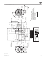
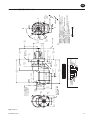
Mounting Dimensions for Series SS850 Starters
(Dwg. TPA832-5)
03531480_ed13
EN
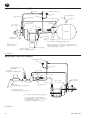
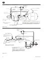
Typical Vehicular Installation (Shown with SS815 Starter)
Starter Control Valve
SMB-618 (Brass)
#4 Hose
Air Pressure Guage
To Relay
Valve
From Starter
Control Valve
#4 Hose
JIC 37º SRV125-1242
"IN" Port JIC 37º
Adapter 1/4" N.P.T.
"OUT" Port JIC 37º
Adapter-1/4" N.P.T.
Air Supply
from Compressor
Check Valve
JIC 37º Adapter
1 - 1/2" N.P.T
1 -1/2" Hose
1 - 1/2"
N.P.T.
Air Receiver
Tank
Lubrication
Supply Line
Air/Gas Starter
Pipe Plug 1/8"-27 PTF
SAE Socket Drive
SRV 150-1-1/2"
Relay Valve
1-1/2" Pipe
* * For natural gas operation, Starter Main Exhaust must be piped away.
NOTE:
Use IR SMB-441 Sealant on all
Pipe Connections
Air/Gas Starter
SS660-A674 Muffler or
SM450-A735 Road Splash
Deflector
To pipe the Drive Housing Vent, remove the Drive Housing Plug and
replace it with a suitable Tubing Line. The tubing must vent at a safe
location and must not be interconnected with any other exhaust lines
which might introduce a back pressure on the Drive Housing Vent.
(Dwg. TPC444-4)
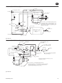
Typical Stationary Installation (Shown with SS815 Starter)
Starter Control
Valve SMB-618
Air Pressure Guage
#4 Hose
Relief Valve set at 15 P.S.I.
above Regulator Setting
#4 Hose
For gas operating the Relief Valve
outlet must be connected into a
safe area.
JIC 37º Adapter
1/4" N.P.T
JIC 37º Adapter 1-1/2" N.P.T
SRV150
1-1/2" Relay Valve
Pressure regulator (maximum setting not to
exceed pressure rating shown on name plate)
High Pressure Supply
1-1/2" Hose
Lubricator
NL-24-8
"IN" Port JIC 37º
Adapter
1/4" N.P.T.
"OUT" Port
JIC 37º Adapter
1/4" N.P.T.
Standard high pressure system air or
gas. Use when supply pressure is over
pressure rating of starter.
* * For natural gas operation, starter main exhaust must be
piped away.
To pipe the Drive Housing Plug, remove the Drive
Housing Plug and replace it with a suitable tubing line.
The tubing must vent at a safe location and must not be
interconnected with any other exhaust lines which might
introduce a back pressure on the Drive Housing Vent.
(Dwg. TPA842-2)
03531480_ed13
EN
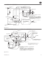
Typical Installation with Engine Prelube System
#4 Hose
Starter Control Valve
SMB-618
Oil Pressure Sensing Valve
Exhaust
#4 Hose
Air Pressure
Gage
"OUT" Port JIC 37°
Adapter 1/4" N.P.T.
"IN" Port JIC 37°
Adapter 1/4" N.P.T.
#4 Hose
For natural gas operation, starter main exhaust
must be piped away.
JIC 37° Adapter
1-1/2" N.P.T.
To pipe the drive housing vent, remove the drive
housing plug and replace it with a suitable tubing
line. The tubing must vent at a safe location and
must not be interconnected with any other
exhaust lines which might introduce a back
pressure on the drive housing vent.
1-1/2" Relay Valve
SRV150
To Prelube Pump
1-1/2" Pipe
JIC 37° Adapter
1/4" N.P.T.
1-1/2" Pipe
1-1/2" Pipe
Lubricator
NL-24-8
#4 Hose
Standard System with Engine
Prelube
Check Valve
150BMP-1054
Tank (maximum pressure not
to exceed pressure rating
on starter nameplate)
**
Supply
1-1/2" Relay Valve
SRV150
(Dwg. TPA843-2)
Typical Installation with Engine Prelube System when Supply Pressure is over Rated Starter Pressure
#4 Hose
JIC 37º Adapter
1/4" N.P.T.
1-1/2" Relay
Valve SRV 150
1-1/2" Pipe
JIC 37º Adapter
1-1/2" N.P.T.
Starter Control Valve
SMB618
1-1/2" Hose
To prelube
pump
Oil Pressure Sensing Valve
Relief Valve set at 15 Psi
above regulator setting.
For gas operation, the
relief valve outlet must
be connected into a safe
place.
Lubricator
NL-24-8
High Pressure Supply
Air Pressure
Gage
#4 Hose
1-1/2" Relay Valve
SRV 150
#4 Hose
"IN" Port JIC 37º
Adapter 1/4" N.P.T.
"OUT" Port JIC 37°
Adapter 1/4" N.P.T.
Pressure regulator (maximum
setting not to exceed pressure
rating shown on starter nameplate)
#4 Hose
High pressure system with engine prelube use
when supply pressure is over rating of starter.
For natural gas operation, starter main exhaust must be
piped away.
To pipe the drive housing vent, remove the drive housing
plug and replace it with a suitable tubing line.
the tubing must vent at a safe location and must not be
interconnected with any other exhaust lines which might
introduce a back pressure on the drive housing vent.
(Dwg. TPA844-2)
03531480_ed13
EN
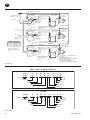
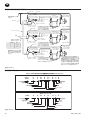
Typical Multiple Starter Installation
#4 Hose
#4 Hose
JIC 37º Adapter
1-1/4" N.P.T.
Starter Control Valve
SMB-618
"OUT" Port JIC 37º
Adapter 1/4" N.P.T.
"IN" Port JIC 37º
Adapter 1/4" N.P.T.
1-1/2" Pipe
1-1/2" Hose
#4 Hose
JIC 37º Adapter
1-1/2" N.P.T.
1-1/2" Relay
Valve SRV150
Lubricator
NL-24-8
#4 Hose
Exhaust piped away for gas
#4 Hose or use muffler SS660-A674
or deflector SM450-A375
1-1/2" Pipe
JIC 37º Adapter
1-1/4" N.P.T.
"OUT" Port
JIC 37º
Adapter
1/4" N.P.T.
"IN" Port JIC 37º
Adapter 1/4" N.P.T.
1-1/2" Pipe
Supply
1-1/2" Hose
JIC 37º Adapter
1-1/2" N.P.T.
Pipe Size
(See Chart)
1-1/2" Relay
Valve SRV150
No. of Starters Min. Pipe Size
2"
2
2-1/2"
3
3"
4
5
3-1/2"
Lubricator
NL-24-8
#4 Hose
Exhaust piped away for gas or
#4 Hose use muffler SS660-A674 or
deflector SM450-A375
JIC 37º Adapter
1/4" N.P.T
"OUT" Port JIC 37º
Adapter 1/4" N.P.T.
"IN" Port JIC 37º
Adapter 1/4" N.P.T.
1-1/2" Pipe
Supply must be adequate
to maintain 120-150 Psig
at the Starters with the Starters
Running.
1-1/2" Hose
JIC 37º Adapter
1-1/2" N.P.T.
1-1/2" Relay
Valve SRV150
Lubricator
NL-24-8
* * For natural gas operation, starter main
exhaust must be piped away.
To pipe the drive housing vent,
remove the drive housing plug and replace
it with a suitable tubing line. The tubing must
vent at a safe location and must not be
interconnected with any other exhaust lines
which might introduce a back pressure on
the drive housing vent.
Exhaust piped away for gas
or use muffler SS660-A674
or deflector SM450-A375
(Dwg. TPA847-2)
How to Order a Starter
MODEL CODING FOR SS815, SS825 AND SS850 STARTERS
SS815
SS825
G
G
B
C
- MODEL CODING 03
R
31 03
R
31 -
O
O
2
2
Size Starter
Type Starter
Gearing
G
G
Drive Housing
Exhaust
Orientation Code
Drive Housing
Rotation
Inlet
Type Pinion
Drive
- MODEL CODING SS850
G
D
09
R
51-
O
2
E
Size Starter
Drive Housing
Type Starter
Exhaust
Orientation Code
Gearing
Drive Housing
Rotation
Inlet
Type Pinion
Drive
(Dwg. TPD1495)
03531480_ed13
ZH
产品安全信息
用途:
此类空气启动器应用于往复式内燃机的启动。此类启动器应在正确安装到需要启动的内燃机上后,进行远程操作。
更多信息请参见内燃机空气启动器产品安全信息手册表 45558624。
手册可从 ingersollrandproducts.com 下载。
使启动器处于使用状态
注
意
对于天然气操作,必须用管道排出起动器的主排气管。
要用管道连接传动箱处排气口,先卸下传动箱阀塞,然后用适当的管线替代。管线必须在安全的位置排气,并且不得与任何其他排气管
线互连,这些管线可能会对传动箱阀产生回压。
润滑
正确润滑对达到起动器的最高性能和最大耐用性非常重要。
建议的两种润滑系统:
Ingersoll Rand No.HDL2 润滑器: 要安装盘车时间期低于 10 秒
的起动器。请按图 TPB978 进行安装。(请参见 EN-4 上 HDL2 滑
润器的安装方式)。使用柴油或 10W 非中性清洁剂机油。
Ingersoll Rand No. NL-24-8 轴向滑润剂:
要安装盘车时间高于 10 秒的起动器。请按管道布置图进行安
装。使用优质的 10W 非中性清洁剂机油来润滑。调整润滑器以使
其每秒涌出 1 至 3 滴。
小
心
在使用 HDL2 润滑器时,请确保油供应管线压力不高于 5 psi。
如果管线上有压力,则润滑剂将通过起动器和排气装置外部继
续渗漏。
安装
注
意
要获得最大性能,请在安装或操作系列 SS815、SS825 和 SS850
起动器之前阅读本手册。
一般信息
1. 我们建议在受到振动的所有车载装置和固定发动机上,应该使
用指定的软管而非刚性管来连接至起动器。车辆和发动机振
动会很快松动刚性管连结,而软管会缓冲此振动,从而使连
结保持紧固。
2. 该起动器供在进口处的法兰装置之用。在安装时,所有管道、
软管和装设阀门都必须清洁、无灰尘和异物。
3. 在实际安装气动起动器的过程中,最好已在接收器中连接软
管,并使软管的起动器末端便于连接到起动器。
4. 通常,发动机设计要求起动器应安装在向下近四分之一处,而
且虽然其中两个装配螺栓孔易于触及,但是第三个孔却常常难
以触到。要安装起动器,需要以下工具: 常用的棘轮扳手、套
筒、万向接头、伸缩套筒和单头或双头套筒扳手。
5. 连结不当会大大削减气动起动器的效率。使用小于所建议尺寸
的软管会使进入马 达内部的空气量减 少,而且使用在排气管
端口内的排放装置(即渐缩管)将会限制排气(对导致性能降
低的发动机造成反压力)。三通和弯头的数量以及供应管线的
长度都应最小化。如果供应管线长达 15 英尺,可使用 1-1/2”
#24 软管或管道;如果供应管线超过 15 英尺,可使用 2”软
管或管道。
6. 活动空气管道中的任何连接装置出现泄漏状况都表明,系统
将会整夜排放并必须在第二天早上通过使用另一台车辆或压
缩机来增压。使连接气泡紧密以避免不必要的费用和延迟。
在整个系统的所有螺纹连接装置上,使用 Ingersoll Rand No.
SMB-441 Sealant、非硬化的 No. 2 Permatex 或 Loctite®* Pipe
Sealant. 务必从接收器的侧面或顶部运行空气供应管线,切勿
在底部或底部附近运行。空气中的水分聚集在接收器的底部,
便可能导致阀门损坏以致无法使用。定时打开箱底部的小龙头
以排出水份。
气动起动器的定向
如果工厂定向因传动箱的径向位置或进气口和/或排气管端口而无
法安装发动机,请按如下方式重新定向起动机:
1. 请参见尺寸图示,另请注意,传动箱 (30) 可位于与齿轮箱 (58)
相对的 16 个径向位置中的任一处。排气管端口(电动机外
壳)(1) 可位于与齿轮箱相对的 4 个径向位置中的任一处,并
且空气进口阀(马外壳盖)可位于与排气管端口相对的 4 个径
向位置中的任一处。另外,可将传动箱安装在位于 3 个径向位
置中任一处的发动机外箱上。
注
意
切勿在定向或安装时分开传动箱和齿轮箱。
2. 学习发动机安装要求,并确定与齿轮箱相对的传动箱的所需定
向。如果传动箱必须重新定位,可卸下 8 个传动箱有头螺丝
(28),然后将传动箱旋转至所需位置。重新安装传动箱有头螺
丝,并将其旋紧至 28 英尺-磅(38 牛米)扭矩。
注
意
切勿在定向或安装时分开马外壳和马外壳盖。
3. 既然已正确定位与齿轮箱相对的传动箱,请注意排气管端口是
否位于底部,以及进气口是否处于有利于软管安装的位置。如
果以上任何一个或两个装置都必须重新定向,可卸下 4 个电动
机外壳盖有头螺丝 (4),然后将电动机外壳和 / 或电动机外壳
盖旋转至所需位置。重新安装电动机外壳盖有头螺丝,并交替
地将其旋紧至 60 英尺-磅(81.4 牛米)扭矩。
安装气动起动器
1. 学习管道布置图。我们强烈建议按如图所示的方式准确连接
起动器。
2. 起动器装置的空气接收箱必须具有工作压力性能(等于或大于
起动器将会操作的最大压力)。
警
告
通过阀或旋塞排出气压。当气罐仍处于增压状态时,切勿从箱上
拔下塞子。
10
*Loctite Corporation 的注册商标。
3. 如果要连接到正在工作的接收箱,可通过打开排水阀排出气
压。排出积聚在罐底部的水份。
03531480_ed13
ZH
注
意
确保已将 SRV150 起动器主 启动阀和气罐连接到继动阀进口侧
(在阀座上标注为字母“IN”) 。
4. 使用 1-1/2” 的短螺纹接套将 SRV150 起动器主 启动阀安装在
气罐末端,如图 TPC444-4(EN-6 上)所示。
5. 请在仪表板上(车载装置)或某些其他相应面板上(固定装
置)安装 No. SMB-618 起动器控制阀。
6. 将 No. TA-STR-100 起动器说明标签贴在邻近起动器阀的控制面
板上。
7. 将 No. 150BMP-1064 压力表安装在控制面板上或邻近控制面板
处。它应位于控制阀操作者容易看到的地方。
注
意
当将起动器控制阀连接到主 动阀时,确保已将软管连接到起动器
控制阀的“SUMP”侧。
8. 将起动器控制阀连接到具有 1/4”#4 软管的继动阀上。使用短
进料软管将此管道中的 T 形管安装到压力计上。
9. 要确定所需的 1-1/2” #24 进气软管的确切长度,可运行大功
率橡胶软管或某些其他相似的大直径软管(从接收器的主启动
阀到发动机的起动器位置)。
10.将 1-1/2” #24 进气软管连接到主启动阀的出口侧,并使软管
从机架等穿过起动器处的最终位置。
11.在此,可在实际安装起动器前后,确定是否可将软管连接到起
动器。在多数情况下,可能需要在安装之前将软管连接到起动
器。
12.请使用优质粘性齿轮润滑油或摩托车链条润滑剂,充分润滑环
形齿轮上的齿轮。这将有助于延长环形齿轮和起动器小齿轮的
寿命。
13.将起动器各就其位,然后将其安装在飞轮外壳上。旋紧安装螺
栓至 100 英寸-磅(136 牛米)扭矩。
14.请在起动器控制阀的“DEL”侧和起动器传动箱上的“IN”端
口之间安装 1/4” #4 软管管线。
16.如果排气装置无法排气,可在起动器的马达外壳的排气管端口
中安装 No. SS660-A674 消声器或 No. SM450-A735 公路防溅导
向板。
17.如果装有起动器的发动机没有外壳(配有标准起动器装置),
以及为该装置制造的托架,我们建议您在起动器的电动机尾部
增加其他支架。为此,马达外壳盖中有 4 个孔。它们是分接的
M10-1.50 以符合米制有头螺丝。
18.将 HDL2 润滑器安装在起动器上或起动器附近,如图
TPB978(在 EN-3 上)所示。
19.加压整个起动系统,并使用皂气泡测试检查各个连接。确保不
会出现渗漏状况。
停止发动机
有时,为了设置喷射器和/或定时,可能需要以此方式(所提供
的活塞可在任何给定地点停止)停止发动机。这可通过 SS815,
SS825 或 SS850 起动器轻易完成。
1. 在传动箱的“OUT”端口拔下 1/4” #4 软管,并使用 1/4” 管道
塞子堵住传动箱中的孔。
2. 从电动机外壳盖中央取下 3/8” 管道塞子。
3. 通过将气压应用于传动箱的“IN”端口,可使用飞轮安装传
动小齿轮。
4. 通过外壳废气盖中的孔插入 3/8”四方传动扳手,以将四方传
动凹槽安装到转子尾部。
5. 手动旋转转子直至发动机弯曲到所需位置。
HDL2 润滑器可自动充满,并可直接安装在起动器上或位于远处。
虽然润滑器能从较安装点低 4 英尺(1.2 米)的油源处吸油,但
Ingersoll Rand 建议将润滑器安装在距油源最近的地方。我们建
议使用非增压回油管线作为润滑剂的来源。但是,也可从单独接
收器或柴油箱供油。当柴油箱是润滑油来源时,可在燃油箱的油
供应管线中安装一个 10 微米至 50 微米的燃油过滤器。润滑剂供
应管线应装入具有 T 形管支管(向下流入润滑器)的回油管线,
以确保润滑器无法吸气而不是油。
15.在起动器传动箱的“OUT”端口和起动器继动阀顶端的小管道
分接部分之间安装 1/4” #4 软管管线。
安装�HDL2�润滑器
气源软管
润滑剂供应软管
润滑剂供应软管
起动器气源或油箱
遥远�安装�HDL2�润滑器
(图. TPB978)
按以下方式安装 HDL2 润滑器:
1. 如果要在起动器上安装 HDL2 润滑器,可从起动器的进口主管
中取下 3/8” 管道塞子,然后将其更换为 HDL2。如果要在远处
安装 HDL2,可使用润滑器可用的两个 U 形螺栓和压板。
2. 如果在远处安装了 HDL2,便可在具有外螺纹和内螺纹的滑润
器末端和起动器进口主管的3/8” 管道分接孔之间安装 1/4” #4
软管。
3. 请在 HDL2 侧的 1/8” NPTF 油进口和非增压燃油管线、柴油箱
或单独油箱之间安装 1/4” 软管。将润滑器的装置旋紧至 15
03531480_ed13
至 36 英寸-磅(20.3 至 40.8 纳米)扭矩。装置的螺纹必须清
洁;不可使用密封剂或 Teflon®* 胶带安装。必须保证连接的
真空严密性。
注
意
在首次操作之前,可手动将油注入供油管线中。
4. 如果使用单独润剂储存罐,可向其中注入柴油或轻质机油
(如 SAE 10 或 10W)。
11
12
Ø 172.0
(Ø 172.0)
108.0
R 86.5 (4.3)
(3.4)
116.0
(4.6)
R 77.5
94.5
(3.1)
(3.7)
M10-1.5 Th'd�型
.63�深�(16.0)�
2�个地方(后方支持)
取下接近�3/8 Sq.
传动支架孔的管道塞子�
端盖
CL 入口
CL
17.5 (.7)
传动箱
23.0(.9)
4 @ 90º
传动箱
16 @ 22 1/2º
10.5(.4)
50.8
(2.0)
45.0
(1.8)
小齿轮运行
导向
D
F
C
G
I
P
2
N
M
L
Ø 146.0
(5.7)
3
Ø�16.6�类型�(0.6)�
3�个地方
逆时针旋转
O
K
顺时针旋转
CL 排气装置
A
J
CL 入口
120° 0’
B
H
52º 30'
mm
(Inch)
双
尺寸
���应该使排气口向下在发动机上安装起动器�
���使用传动箱上侧控制油口的设置�
���这些型号不能用于起动器暴露在变速器液中的情况�
���传动箱定向代码取决于控制油口相反方向的安装孔位置�
���除非另行指定,否则将以�(02G)�显示的标准方向进行装运�
���请在尝试重新定向前阅读说明�
���起动器重量���43.1�千克(95�磅)
注意�
1E
控制油口 CL
飞轮齿圈表面
28.5
(1.1)
Ø 92.00
(3.6)
仅适用于阀塞�
SS825
传动箱
排气装置
定向代码
入口
小齿轮类型
驱动形式
-型号编码B 03 R 31- 0 2 G
定向选项
排气装置
SS815 G
138.5(5.5)
1/4-18 N.P.T.
控制油口出口
1/4-18 N.P.T.�
控制油口进口
159.5
(6.3)
CL
入口
322.0
(12.7)
齿轮箱
85.7
(3.4)
4 @ 90º
起动器尺寸
起动器类型
齿轮
传动箱
旋向
447.7
(17.6)
434.0
(17.1)
10.0
(.4)
222.5(8.8)
Ø152.0
(6.0)
2 1/2-8 NPT
C
L 排气装置
马达外壳
润滑器连接两侧�
419.5
(16.5)
ZH
SS815 和 SS825 系列起动器的安装尺寸
(图. TPA1325-1)
03531480_ed13
03531480_ed13
Ø 172.0
108.0
(4.3)
53.2
(2.1)
M10-1.5 Th'd 型 (.63) 深 16.0 2 个地方(后方支持)
R 48.7
(1.9)
R 43.6
(1.7)
65.2
(2.6)
取下接近 3/8 Sq. 传动支架孔的管道塞子.
SS850
375.0
(14.8)
263.0
(10.4)
1/4-18 N.P.T. 控制油口进口
Ø 110.2
(4.3)
168.0
(6.6)
传动箱
排气装置
定向代码
入口
小齿轮类型
驱动形式
02E
传动箱
16 @ 22 1/2º
-型号编码-
B 09 R 51-
定向选项
入口 排气装置
4 @ 90º 4 @ 90º
G
48.2
(1.9)
齿轮箱
2 1/2-8 NPT
排气装置
马达外壳
起动器尺寸
起动器类型
齿轮
传动箱
旋转
端盖
润滑器连接两侧.
1 1/2 - 11 1/2 NPT
入口
361.5
(14.2)
28.5
(1.1)
18.0
(.7)
20.0
(.8)
186.5
(7.3)
传动箱
10.7
(.4)
1/4-18 N.P.T. 控制油口出口
180.0
(7.1)
R 64.3
(2.5)
控制油口
1
90º Typ.
D
E
F
G
45º
C
B
H
入口
J
P
2
O
K
N
L
3
Ø 17.5 (.68) 类型 3 个地方
M
逆时针旋转
顺时针旋转
排气装置
A
I
Ø
mm
(Inch)
双
尺寸
1. 应该使排气口向下在发动机上安装起动器.
2. 使用传动箱上侧控制油口的设置.
3. 这些型号不能用于起动器暴露在变速器液中的情况.
4. 传动箱定向代码取决于控制油口相反方向的安装孔位置.
5. 除非另行指定,否则将以 (02E) 显示的标准方向进行装运.
6. 请在尝试重新定向前阅读说明.
7. 起动器重量 = 25.4 千克(56 磅)
注意:
飞轮齿圈表面
导向
152.3
(6.0)
23.34
(.9)
ZH
SS850 系列起动器的安装尺寸
(图. TPA832-5)
13
ZH
典型的车载安装(通过 SS815 起动器显示)
#4�号软管
起动器控制阀�SMB-618(铜)
压力表
进至主启动阀
�始于起动器控制阀
JIC 37º SRV125-1242
检查阀门
JIC 37º�接头�
1 - 1/2" N.P.T.
“进口”端�JIC 37º�
�接头�1/4" N.P.T.
“出口”端�JIC 37º�
�接头�� 1/4" N.P.T.
来自压缩机的气源
#4�号软管
1 -1/2"�软管
1 - 1/2"
N.P.T.
空气储气罐
润滑系统供应管线
空气�气动起动器
管道塞子�1/8"-27 PTF�
SAE�套筒传动
SRV 150-1-1/2"�
主启动阀
1-1/2"�管道
* * 对于天然气操作,必须用管道排出起动器的主排气管.
注意:
在所有管道连接处使用�
IR SMB-441�密封胶
空气�气动起动器
要用管道连接传动箱阀,先卸下传动箱阀塞,然后用适当的管线替代�
管线必须在安全的位置排气,并且不得与任何其他排气管线互连,这些管
线可能会对传动箱控制气口处产生回压.
SS660-A674�消声器或�
SM450-A735�公路防溅导向板
(图. TPC444-4)
典型的固定安装(通过 SS815 起动器显示)
起动器控制阀�SMB-618
压力表
#4�号软管
以超出调节器设置的�15 Psi�
的减压阀设置
#4�号软管
对于气体操作,
必须将减压阀出口连接到安全的地方�
JIC 37º�接头�
1/4" N.P.T.
SRV150
1-1/2"�主启动阀
压力调节器
�最大设置不超过商标上显示的额定压力)
JIC 37º�接头�1 -1/2" N.P.T.
1 -1/2" 软管
“进口”端�JIC 37º
�接头�1/4" N.P.T.
“出口”端�JIC 37º�
�接头�1/4" N.P.T.
润滑器�NL-24-8
高压供应
标准高压系统空气或气体��
在供应压力超过起动器的额定压力时使用�
* * 对于天然气操作,必须用管道排出起动器的主排气管.
要用管道连接传动箱阀,先卸下传动箱阀塞,
然后用适当的管线替代��管线必须在安全的位置排气,
并且不得与任何其他排气管线互连,
这些管线可能会对传动箱控制气口处产生回压.
(图. TPA842-2)
14
03531480_ed13
ZH
具有发动机预先润滑系统的典型安装
#4�号软管
起动器控制阀�SMB-618
油压感应阀
排气装置
“出口”端�JIC 37º�
�接头�1/4" N.P.T.
#4�号软管
“进口”端�JIC 37º�
�接头�1/4" N.P.T.
气压计
#4�号软管
对于天然气操作,必须用管道排出起动器的主排气管.
JIC 37º�接头�
1 -1/2" N.P.T.
要用管道连接传动箱阀,先卸下传动箱阀塞,然后用
适当的管线替代��管线必须在安全的位置排气,并且
不得与任何其他排气管线互连,这些管线可能会对传
动箱控制气口处产生回压.
1-1/2"�主启动阀�
SRV150
1-1/2"�管道
JIC 37º 接头�
1/4" N.P.T.
要预先润滑泵
1-1/2"�管道
检查阀�
150BMP-1054
储气罐��最大压力不超
过起动器商标上显示的
额定压力)
1-1/2" 管道
润滑器 NL-24-8
供应
**
#4 号软管
具有发动机预先润滑的标准系统
1-1/2" 主启动阀�
SRV150
(图. TPA843-2)
具有发动机预先润滑系统的典型安装时供应压力超过起动器压力的额定值。
1-1/2"�主启动阀�
SRV 150
JIC 37º 接头�
1/4" N.P.T.
JIC 37º�接头�
1 -1/2" N.P.T.
1-1/2"�管道
以超出调节器设置的�15 Psi��
的减压阀设置�
油压感应阀
#4�号软管
对于气体操作,必须将减
压阀出口连接到安全地方.
润滑器�
NL-24-8
高压供应
要预先润滑泵
起动器控制阀�SMB618
压力表
#4�号软管
1 -1/2"�软管
1-1/2"�主启动阀�
SRV 150
减压阀(最大设置不超过起动器商标
上显示的额定压力�
#4�号软管
“进口”端�JIC 37º�
�接头�1/4" N.P.T.
“出口”端�JIC 37º�
�接头�1/4" N.P.T.
#4�号软管
具有发动机预先润滑的高压系统在供应压力超过
起动器额定压力时使用.
对于天然气操作,必须用管道排出起动器的主排气管.
要用管道连接传动箱阀,先卸下传动箱阀塞,然后用适当的管线替代��
管线必须在安全的位置排气,并且不得与任何其他排气管线互连,
这些管线可能会对传动箱控制气口处产生回压.
(图. TPA844-2)
03531480_ed13
15
ZH
典型多起动器安装
#4�号软管
#4�号软管
“出口”端�
�JIC 37º�接头
�1/4" N.P.T.
“进口”端�JIC 37º�
�接头�1/4" N.P.T.
JIC 37º 接头�
1 -1/4" N.P.T.
1-1/2"�管道
起动器控制阀�
SMB-618
1 -1/2"�软管
#4�号软管
JIC 37º�接头�
1 -1/2" N.P.T.
润滑器�NL-24-8
1-1/2"�主启动阀�
SRV150
1-1/2"�管道
JIC 37º�接头�
1 -1/4" N.P.T.
1-1/2"�管道
“出口”端�
�JIC 37º�接头
�1/4" N.P.T.
“进口”端�JIC 37º�
�接头�1/4" N.P.T.
1 -1/2"�软管
供应
JIC 37º�接头�
1 -1/2" N.P.T.
管道尺寸
�参阅图表)
马达数量
2
3
4
5
#4�号软管
管道排气装置或使用消声器�
SS660-A674�或导向板�
SM450-A375
#4�号软管
润滑器�NL-24-8
1-1/2" 主启动阀�
SRV150
���管子大小
2"
2-1/2"
3"
3-1/2"
#4 号软管
JIC 37º�接头�
1 -1/4" N.P.T.
1-1/2"�管道
供应必须是充分的维护
120-150 Psig�在起始者以起始
者跑。
#4�号软管
管道排气装置或使用消声器�
SS660-A674�或导向板�
SM450-A375
“出口”端�JIC 37º�
�接头�1/4" N.P.T.
“进口”端�JIC 37º�
�接头�1/4" N.P.T.
1 -1/2"�软管
JIC 37º�接头�
1 -1/2" N.P.T.
润滑器�NL-24-8
1-1/2"�主启动阀�
SRV150
管道排气装置或使用消声器�
SS660-A674�或导向板�
SM450-A375
* * 对于天然气操作,必须用管道排出起动器
的主排气管.
要用管道连接传动箱排气口,
先卸下传动箱阀塞,然后用适当的管线替代。�
管线必须在安全的位置排气,
并且不得与任何其他排气管线互连,
这些管线可能会对传动箱控制气口处产生回压
(图. TPA847-2)
如何订购起动器
SS815��SS825�和�SS850�代码编号含义
SS815
SS825
G
G
B
C
�型号编码�
03
R
31 03
R
31 -
O
O
2
2
起动器尺寸
G
G
传动箱
排气装置
定向代码
起动器类型
齿轮
传动箱
旋转
入口
小齿轮类型
驱动形式
�型号编码�
SS850
G
D
09
R
51-
O
2
E
传动箱
起动器尺寸
排气装置
起动器类型
定向代码
齿轮
传动箱
旋转
入口
小齿轮类型
驱动形式
(图. TPD1495)
16
03531480_ed13
JA
製品に関する安全性
製品に関する安全性
これらのエアスターターは、往復内燃機関の始動に使用することを目的としています。これらのエアスターターは、始動させる必要のある往復内
燃機関に正しく取り付けた後、離れた場所から操作するように設計されています。
詳細は、
「内燃機関用エアスターター製品安全情報説明書 45558624」
を参照してください。
irools.com から説明書をダウンロードすることができます。
始動装置の供用
天然ガス運転をする場合、始動装置のメイン排気は、配管で排出する必要があります。
駆動部筐体排出口に配管するために、駆動部筐体栓を外して適切な管類ラインに取り換えます。管類は、安全な位置で排気する必要があり、
駆動部筐体の排出口に逆圧の発生を招くおそれのある他の排気ラインとの相互接続をしないようにする必要があります。
潤滑
適切な lubrication は、始動装置の、最高の性能および最大の耐久
性を得るのに必須です。
2 種類の lubrication システムを推奨します。
Ingersoll RandNo. HDL2 ルブリケータ。クランキング サイクルが
10秒以下の始動装置の再組付けの場合。図面 TPB978.に示されて
いるように再組付けします。(EN-4 に記載されている HDL2 ルブリケ
ータの再組付けを参照してください)。.ディーゼル燃料または 10W
非洗浄性モーター オイルで潤滑します。
Ingersoll Rand No. NL-24-8 インライン ルブリケータ。
クランキング サイクルが10秒より長い始動装置の再組付けの場
合。配管図に示されるように再組付けします。良質の 10W 非洗浄
性モーター オイルで潤滑します。ルブリケータを1秒間に1~3滴流
れるように調整します。
HDL2 ルブリケータをご使用になるときは、すべての給油ラインの圧
力が 5 psi を超えていないことを確認します。ラインに圧力が掛かっ
ている場合、ルブリケータは、常に、始動装置を通って排気管の外に
潤滑剤を漏出します。
再組付け
最高の性能を得るために、
シリーズ S815,SS825 および SS850 始
動装置の再組付けまたは運転の前にこの取扱説明書を熟読してく
ださい。
一般情報
1. すべての車両への再組付けおよび振動に晒される固定エンジ
ンについて、始動装置に配管による固定した接続を行うのでな
く、規定の口径のホースをご使用になることを推奨します。車両
およびエンジンの振動により固定した配管接続は直ぐ緩みます
が、ホースの場合、振動を吸収し、接続は強固なままです。
2. この始動装置は、吸気口でフランジに取り付けられるように設
計されています。すべての配管ホースおよび取付金具は、再組
付け中に、清浄で、ほこりおよび異物がないようにする必要が
あります。
3. 空気始動装置を実際に取り付ける場合は、ホースは前以て受け
器側での接続を済ませ、始動装置側の端は、始動装置に取り付
けられるように近くに置いておくのが最も適切です。
4. エンジンの設計により、始動装置が非常に近接した部屋の下に
取り付けられ、2つの取り付けボルト用穴は、容易に手が届くにも
拘らず、3つ目に穴が、
しばしば手が届きにくいということが頻繁
に要求されます。始動装置を再組付けするには以下の工具が必
要です。レギュラー ラチェット レンチ、
ソケット、
自在継手、
ソケッ
ト伸長器および片口または両口のボックス レンチ
5. [空気始動装置] の効率は、不適切な接続によって非常に損なわ
れることがあります。推奨したホースより小さいホースは、モー
ターへ送る空気量を減少させ、排気ポート内の、配管による排出
用の抑制器を使用すると、排気を制限し、
これによりモーターに
逆圧を生じさせ、結果的に性能を低下をもたらします。T字型分
岐および肘継手の数量および供給ライン長さは最小限に抑えて
ください。15 フィート長までの供給ラインには1-1/2” インチ#24
のホースまたはパイプを使用し、15 フィート長を超える場合は、
供給ラインには 2 インチのホースまたはパイプを使用します。
* Loctite Corporation の登録商標.
03531480_ed13
6. 使用中の送気管のどこかの接続部に漏れがあるということは、
シ
ステムが一晩中空気を流出しているということであり、翌朝、別
の車両またはコンプレッサを使用して元通りに圧力を上げる必
要があります。接続部から気泡が漏れないように締め付け、不要
なコストや遅れの発生を避けます。システム全体のすべてのネ
ジ接続は、Ingersoll Rand No. SMB-441 シーリング材ト、非硬化
剤 No. 2 Permatex または Loctite®* パイプ シーリング材を使用し
ます。常に、
ご使用の給気ラインを受け器の側面または最上部
から敷くようにし、決して底部またはその付近から敷くことのな
いようにします。空気中の湿気は、受け器の底に集まり、バルブ
の動作不能を引き起こすおそれのある損傷をもたらします。定
期的に、
タンクの底部のコックを開放して排水します。
空気始動装置の方向
工場で設定された方向が、[駆動部筐体] の放射状配置または吸
気/排気ポートの配置のためにご使用のエンジンに合わない場合、
以下のようにして [始動装置] の方向を変えてください。
1. 寸法入りの説明図をご覧になり、[駆動筐体] (30) が [変速装置]
(58) に対して16箇所の放射状位置のどの位置にも配置できるこ
とにご注意ください。
排気ポート ([モーター筐体]) (1) は [変速装置] に対し、4 箇所の
放射状位置のどの位置にも配置でき、吸気口 ([モーター筐体カ
バー]) は、排気ポートに対して4箇所の放射状位置のどの位置に
も配置できます。また、[駆動部筐体] も 3箇所の放射状位置のど
の位置のエンジン ベル筐体上にも再組付けできます。
方向変更時または再組付け時に [駆動部筐体] を [変速装置] から分
離させないでください。
2. エンジンの取り付け要求を検討し、[変速装置] に対する [駆動部
筐体] の必要な方向を決定します。[駆動部筐体] の方向を変え
る必要がある場合、8本の [駆動部筐体キャップ ネジ] (28) を外
し、[駆動部筐体] を要求された位置に回転させます。[駆動部筐
体キャップ ネジ] を元通りに再組み付けして 28 ft-lb (38 Nm) の
トルクで締め付けます。
17
JA
方向変更時または再組付け時に [モーター筐体] を [モーター筐体カ
バー] から分離させないでください。
3. ここで、[駆動部筐体] は、[変速装置] に対して正しい方向にする
ことができたので、排気ポートが底にあるかないか、および吸気
口が、ホースの再組付けに対し、好ましい位置に配置されている
かに注意します。これらの構成部品の片方または両方の方向を
変える必要がある場合、4個の [モーター筐体カバー ネジ] (4) を
外して [モーター筐体]/[モーター筐体カバー] を希望する位置に
回転させます。[モーター筐体カバー キャップ ネジ] を元通り再
組み付けして 60 ft-lb (81.4 Nm) のトルクで固く締め付けます。
空気始動装置の取り付け
1. 配管図の検討 [始動装置] が表示されたように正しく接続される
ことを強く推奨します。
2. [始動装置] 再組付け用の空気受けタンクは、[始動装置] が運転
される最大圧力以上の動作圧力性能を有する必要があります。
空気圧をバルブまたはコックを通して徐々に減らして無くします。タ
ンク内にまだ圧力が加わっている間にタンクから栓を抜かないでく
ださい。
3. 既に使用中の受けタンクに接続しようとする場合、
ドレイン バル
ブを開放して、空気圧を徐々に減らして無くします。タンクの底
に溜まった水があれば排出します。
SRV150 始動装置リレーバルブ と [受けタンク] が、バルブ本体に刻
印された「 IN (入) 」
という言葉によって示された SRV150 始動装置リ
レーバルブの吸気口側で接続されていることを確認します。
4. 1-1/2 インチ ショート ニップルを使用して、EN-6上の図面
TPC444-4に示されているように受けタンクの端に SRV150 始
動装置リレーバルブを 再組付けします。
5. ダッシュパネル (車両再組み付け用) または他の適切なパネル
(固定再組み付け用) に、No. SMB-618 始動装置制御バルブ を再
組付けします。
6. [始動装置制御バルブ] に隣接する制御パネルに No. TA-STR-100
始動装置指示ラベルを貼り付けます。
7. No. 150BMP-1064 風圧計を制御パネルまたはその周りに取り付
けます。風圧計は、[制御バルブ] の運転員が容易に見ることの
できる場所に配置してください。
[始動装置制御バルブ] を [リレー バルブ] に接続するときは、ホース
が、[始動装置制御バルブ] の ” SUMP” 側に接続されていることを
確認します。
8. [始動装置制御バルブ] と [リレーバルブ] を 1/4 インチ #4 ホー
スで接続します。このラインに [風圧計] に至る短いフィーダー
ホースの付いたT字型分岐を取り付けます。
9. 頑丈な庭園用ホースなどの大きな直径のホースを受け器の [リ
レーバルブ] からエンジンの始動装置の位置まで敷き、必要な
1-1/2 インチ #24 空気ホースの正確な長さを決定します。
10.[リレーバルブ] の排気側に1-1/2 インチ #24 の空気ホースを取
り付け、
このホースをフレームなどを通って始動装置がある最
終位置まで敷きます。
11.この地点で、[始動装置] が実際に取り付けられる前または後に、
ホースを [始動装置] に付けることが実際的か、
またはそうでな
いかを決定します。多くのケースで、[始動装置] を取り付ける前
に、ホースを [始動装置] に取り付けることが必要である場合が
あります。
18
12.リング ギアに良好な粘着性のある、ギア グリースまたはオート
バイのチェーン用潤滑油を十分に塗ります。こうすると、
リング
ギアおよび始動装置のピニオンの寿命を延ばすのに役立ちま
す。
13.[始動装置] を所定の位置に移動し、
フライホイール ベル筐体上
に取り付けます。取り付けボルトを100 ft-lb (136 Nm) のトルクま
で締め付けます。
14.[始動装置制御バルブ] の ” DEL “ 側から [始動装置駆動筐体] 上
の ” IN “ ポートに1/4 インチ #4 ホース ラインを再組付けしす。
15.1/4 インチ #4 ホース ラインを [始動装置駆動部筐体] 上の ”
OUT “ ポートから [始動装置リレーバルブ] の上端の小管のタす。
16.排気が配管で排出されなかった場合、[始動装置] のモーター筐
体上の排気ポートに No. SS660-A674 マフラー または
No. SM450-A735 道路泥除け装置を再組付けします。
17.[始動装置] が取り付けられているエンジンが標準の始動装置台
座の付いたベル筐体が無い場合、および取付け用ブラケットを
製作する必要がある場合、[始動装置] のモーターの末端に支持
用ブラケットを追加されることを推奨します。[モーター筐体カ
バ] ーに、
この目的用として4箇所の穴があります。これらの穴に
は、
メートル押さえネジが収まるように M10-150 のタップが切ら
れています。
18.EN-3 の図面TPB978 に表示されているように、[始動装置] または
その付近に HDL2 ルブリケータを 取り付けます。
19.始動システム全体に圧力をかけ、すべての接続部をせっけん泡
試験でチェックします。漏れが全く無いことが必要です。
エンジン全体の封じ込み
ときどき、インジェクターの設定およびタイミング調整の両方、
また
はどちらか一方の目的のために、
どのようなピストンも、
どのような
指定位置にも停止できるような方法でエンジンを封じ込むことが望
ましい場合があります。これは、SS815, SS825 および SS850 の各始
動装置で非常に簡単に実施できます。
1. [駆動部筐体] 上の ” OUT “ ポートにある1/4 インチ #4 ホースを
外し、[駆動部筐体] の穴を1/4 インチ パイプ栓で塞ぎます。
2. [モーター筐体カバー] の中央から 3/8 インチ パイプ栓を外し
ます。
3. フライホイールの付いた [駆動ピニオン] を圧力を加えて [駆動
部筐体] 上の ”IN “ ポートにはめ込みます。
4. [モーター筐体カバー] の穴に 3/8 インチのスクエア ドライブ レ
ンチを挿入してローターの後部の凹みにスクエア ドライブを
はめ込みます。
5. エンジンが希望の位置にクランクで回転するまで [ローター] を
手動で回転させます。
HDL2 ルブリケータは自給式で、[始動装置] 上に直接再組付けする
かまたは離して配置することができます。ルブリケータは、再組付け
位置から 4 ft (12m) 低い供給源から潤滑油をくみ上げることができ
ますが、Ingersoll Rand は、ルブリケータをできるだけ油供給源の
近くに再組付けすることを推奨します。潤滑油の供給源として圧力
の加わらない燃料戻りラインの使用を推奨します。しかし、油は、別
の容器またはジーゼル燃料タンクからも供給できます。ディーゼル
燃料タンクが潤滑油供給源であるときは、10 ~ 50 ミクロンの燃料フ
ィルターを燃料タンクの油供給ラインに再組付けします。潤滑油供
給ラインが、T字型分岐の脚が下向きでルブリケータに向かい、ルブ
リケータが油の代わりに空気を取り込むことがないことを保証にラ
インに流れ込むようにしてください。
03531480_ed13
JA
HDL2 ルブリケータの再組付け
空気供給ホース
潤滑油供給ホース
潤滑油供給ホース
始動装置空気供給室または油室
遠隔 HDL2 ルブリケータの再組付け
(図面. TPB978)
HDL2 ルブリケータを以下のように取り付けます。
1. HDL2 ルブリケータを [始動装置] 上に取り付けようとする場合、
[始動装置] の吸入口の突起から 3/8 インチパイプ栓の内の1つ
を外してHDL2と取り替えます。HDL2 を離れた位置に取り付ける
場合、ルブリケータ用に使用できる 2本のU ボルトおよび基礎取
付金具を使用します。
2. HDL2 を離れた位置に取り付けた場合、雄ネジ、雌ネジの両方
を有するルブリケータの末端から [始動装置] 吸入口の突起上
の 3/8 インチ管のタップ付きの穴の内の1つに 1/4” #4 ホースを
再組付けします。
3. HDL2 の側面の 1/8” インチ NPTF 注油口から圧力の加わらない
燃料ライン、ディーゼル燃料タンクまたは別の油容器に 1/4 イ
ンチホースを再組付けします。ルブリケータの取り付け金具を
15 ~ 36 ft-lb (20.3 ~ 40.8 Nm) のトルクで締め付けます。取り付
け金具上のネジは清浄にする必要があり、
シーリング材または
Teflon®* テープを使用せずに取り付け金具を組み立てます。接
続は、真空気密にする必要があります。
初期運転の前に、手動で油供給ラインを一杯にします。
4. 別の潤滑油タンクを使用する場合、
このタンクを SAE10 また
は 10W のようなディーゼル燃料または薄いモーター オイルす。
03531480_ed13
19
Ø 172.0
(Ø 172.0)
108.0
R 86.5 (4.3)
(3.4)
116.0
(4.6)
R 77.5
94.5
(3.1)
(3.7)
M10-1.5ネジで、0.63
深さ (16.0)のもの 2箇
所(後部支持用)
ローターにある3/8スクエアド
ライブ封じ込み穴へのアクセス
用のパイプ栓を外します。
4 @ 90º
16 @ 22 1/2º
駆動部筐体
排気管
方向コード
吸気口
ピニオンタイプ
駆動
-モデルコーディングSS815 G B 03 R 31- 0 2 G
4 @ 90º
10.5(.4)
パイロット
備考:
D
F
C
G
I
A
P
J
2
CL 排気管
120° 0’
B
H
CL 吸気口
Ø
52º 30'
Ø 146.0
(5.7)
3
左回り回転
N
M
L
Ø16.6 タイプ(0.6)
3-箇所
右回り回転
O
K
mm
(Inch)
二重の
寸法
1. [始動装置]は、排気管を下に向けてエンジンに再組付けしてください。
2. [駆動部筐体]の上側の[制御ポート]セットを使用してください。
3. これらのモデルは、始動装置がトランスミッション液に晒されるよ
うな用途への使用は認められていません。
4. [駆動部筐体]方向コードは、[制御ポート]の反対側にある取り付け
置に基いています。
5. 他に指定の無い限り、表示されている(02G)標準方向で出荷されます。
6. 方向を変えようとする前に説明書を熟読してください。
7. 始動装置重量=43.1 Kg (95 Lbs.)
リングギア外観
1E
制御ポート C
L
28.5
(1.1) ピニオン行程
Ø 92.00
(3.6)
排気栓
SS825のみ
45.0
1/4-18 N.P.T.
(1.8)
制御ポート
出口
50.8
159.5
(2.0)
(6.3)
CL
17.5 (.7)
駆動部
筐体
23.0(.9)
1/4-18 N.P.T.
制御ポート
出口
138.5(5.5)
方向オプション
吸気口 排気管 駆動部筐体
サイズ始動装置
始動装置タイプ
歯車装置
駆動部筐体
回転
447.7
(17.6)
434.0
(17.1)
322.0
(12.7)
85.7
(3.4)
CL
222.5(8.8)
10.0
(.4)
Ø152.0
(6.0)
CL 2 1/2-8 NPT
排気管
モーター筐体
両側ルブリ
ケータ接続.
CL 吸気口
カバー
20
変速装置
419.5
(16.5)
JA
SS815 および SS825 シリーズ始動装置の取り付け寸法
(図面. TPA1325-1)
03531480_ed13
03531480_ed13
Ø 172.0
108.0
(4.3)
カバー
SS850
375.0
(14.8)
263.0
(10.4)
1/4-18 N.P.T.
制御ポート出口
48.2
(1.9)
Ø 110.2
(4.3)
168.0
(6.6)
G
駆動部筐体
排気管
方向コード
吸気口
ピニオン タイプ
駆動
-モデル コーディングB 09 R 51- 0 2 E
方向オプション
吸気口 排気管
駆動部筐体
16 @ 22 1/2º
4 @ 90º 4 @ 90º
排気管
2 1/2-8 NPT
モーター筐体
両側ルブリケータ接続
1 1/2 - 11 1/2 NPT
吸気口
サイズ始動装置
始動装置タイプ
歯車装置
駆動部筐体
回転
53.2
(2.1)
M10-1.5 ネジで、(0.63)
深さ 16.0 のもの 2箇所
(後部支持用)
R 48.7
(1.9)
R 43.6
(1.7)
65.2
(2.6)
ローターにある 3/8 ス
クエア ドライブ封じ込
み穴へのアクセス用の
パイプ栓を外します。
変速装置
361.5
(14.2)
28.5
(1.1)
186.5
(7.3)
18.0
(.7)
20.0
(.8)
駆動部筐体
10.7
(.4)
1/4-18 N.P.T.
制御ポート出口
180.0
(7.1)
R 64.3
(2.5)
E
F
制御ポート
D
1
90º Typ.
G
45º
C
B
H
2
P
N
L
M
3
Ø 17.5
(.68) タイプ
3-箇所
左回り回転
O
K
右回り回転
排気管
J
吸気口
A
I
Ø
mm
(Inch)
二重の
寸法
備考:
1. [始動装置] は、排気管を下に向けてエンジンに再組付けしてください。
2. [駆動部筐体] の上側の [制御ポート] セットを使用してください。
3. これらのモデルは、始動装置がトランスミッション液に晒されるよ
うな用途への使用は認められていません。
4. [駆動部筐体] 方向コードは、[制御ポート] の反対側にある取り
付け穴の位置に基いています。
5. 他に指定の無い限り、表示されている (02E) 標準方向で出荷されます。
6. 方向を変えようとする前に説明書を熟読してください。
7. 始動装置重量 = 25.4 Kg (56 Lbs.)
リング ギア外観
パイロット
152.3
(6.0)
23.34
(.9)
JA
SS850 シリーズ始動装置の取り付け寸法
(図面. TPA832-5)
21
JA
典型的な車両再組付け (SS815 始動装置で表示)
始動装置制御バルブ
SMB-618(真ちゅう
#4ホース
風圧計
リレーバルブへ
始動装置制御
バルブから
JIC 37º SRV125-1242
チェックバルブ
JIC 37ºアダプタ
1 - 1/2インチ N.P.T.
“IN” ポートJIC 37º
アダプタ1/4インチN.P.T.
“OUT”ポートJIC 37º
アダプタ-1/4 インチ N.P.T.
コンプレッサーからの空気供給
#4ホース
1 -1/2インチホース
1 - 1/2"
N.P.T.
空気だめタンク
注油供給ライン
空気/ガス始動装置
パイプ栓 1/8 インチ-27 PTF
SAEソケット駆動
SRV 150-1-1/2
インチリレーバルブ
1-1/2インチパイプ
* * 天然ガス運転をする場合、始動装置のメイン排気は、配管で排出する必要があります。
備考:
すべてのパイプ接続にIR SMB-441
シール材を使用します。
空気/ガス始動装置
駆動部筐体通気口に配管するために、駆動部筐体栓を外して適切な管類ラインに取り
換えます。管類は、安全な位置で排気する必要があり、[駆動部筐体]に逆圧の発生を
招くおそれのある他の排気管との相互接続をしないようにする必要があります。
SS660-A674マフラーまたは
SM450-A735道路泥除け装置
(図面. TPC444-4)
典型的な車両再組付け (SS815 始動装置で表示)
始動装置制御バルブ
SMB-618
風圧計
#4ホース
レギュレータ設定より15 Psi
上のリリーフバルブセット
ガス運転に対しては、
リリーフバル
ブ出口は、安全な地域に接続される
必要があります。
#4ホース
JIC 37ºアダプタ
1/4” インチ N.P.T.
SRV150 1-1/2
インチリレーバルブ
圧力レギュレータ(銘板に表示された圧力定格を
超えない最大設定)
JIC 37º アダプタ1 -1/2インチ N.P.T.
1 -1/2インチホース
“IN”ポート
JIC 37ºアダプタ
1/4インチN.P.T.
“OUT”ポートJIC 37º
アダプタ1/4インチ-
ルブリケータ
NL-24-8
高圧供給
標準高圧システム空気またはガス供給圧力
が始動装置の定格以上のとき、使用します。
* * 天然ガス運転をする場合、始動装置のメイン排気は、配管で
排出する必要があります。
[駆動部筐体栓]に配管するために、[駆動部筐体栓]を外して
適切な管類ラインに取り替えます。管類は、安全な位置で排気
する必要があり、[駆動部筐体]に逆圧の発生を招くおそれの
ある他の排気管との相互接続をしないようにする必要があり
ます。
(図面. TPA842-2)
22
03531480_ed13
JA
エンジン潤滑前システムの典型的再組付け
#4ホース
始動装置制御バルブ
SMB-618
油圧検出バルブ
排気管
“OUT” ポートJIC 37º
アダプタ1/4インチ
N.P.T.
#4ホース
“IN” ポートJIC 37º
アダプタ1/4“インチ
N.P.T.
風圧計
#4ホース
天然ガス運転をする場合、始動装置のメイン排気は、配
管で排出する必要があります。
JIC37ºアダプタ
1-1/2”インチN.P.T.
[駆動部筐体通気孔]に配管するために、[駆動部筐体栓]
を外して適切な管類ラインに取り換えます。管類は、安全
な位置で排気する必要があり、[駆動部筐体]に逆圧の発
生を招くおそれのある他の排気管との相互接続をしない
ようにする必要があります。
SRV150 1-1/2
インチリレーバルブ
1-1/2インチパイプ
JIC37ºアダプタ
1/4”インチN.P.T.
潤滑前ポンプへ
1-1/2”インチパイプ
チェックバルブ150BMP-1054
タンク(始動装置銘板に表
示された圧力定格を超えな
い最大圧力)
1-1/2インチパイプ
ルブリケータNL-24-8
#4ホース
エンジン潤滑前の機能の付いた
標準システム
**
供給
SRV150 1-1/2 インチ
リレー バルブ
(図面. TPA843-2)
供給圧力が定格始動装置圧力を超えたときのエンジン潤滑前システムの典型的再組付け
JIC 37ºアダプタ
1/4インチN.P.T.
1ー1/2インチリレ
ーバルブSRV 150
1-1/2インチパ
イプ
JIC 37ºアダプタ
1 -1/2インチN.P.T.
レギュレータ設定より15 Psi
上のリリーフバルブセット。
油圧検出バルブ
#4ホース
ガス運転に対しては、
リリ
ーフバルブ出口は、安全な
地域に接続される必要が
あります。
ルブリケータ
NL-24-8
高圧供給
潤滑前ポンプへ
始動装置制御バルブ
SMB618
風圧計
1ー1/2インチ
リーバルブSRV 150
#4ホース
1 -1/2インチホース
圧力調整器(始動装置銘板に表示され
た圧力定格を超えない最大設定)
#4ホース
“IN”ポート
JIC 37ºアダプ
タ1/4インチ
N.P.T.
“OUT”ポートJIC 37ºアダ
プタ1/4インチN.P.T.
#4ホース
供給圧力が始動装置の定格を超えるときのエンジ
ン潤滑前機能を有する高圧システムの使用。
天然ガス運転をする場合、始動装置のメイン排気は、配管で排出
する必要があります。
[駆動部筐体通気孔]に配管するために、[駆動部筐体栓]を外し
て適切な管類ラインに取り換えます。管類は、安全な位置で排気
する必要があり、[駆動部筐体]に逆圧の発生を招くおそれのある
他の排気管との相互接続をしないようにする必要があります。
(図面. TPA844-2)
03531480_ed13
23
JA
典型的な複式始動装置の再組付け
#4ホース
#4ホース
JIC 37ºアダプタ
1 -1/4インチN.P.T.
始動装置制御バルブ
SMB-618
1-1/2インチパイプ
#4ホース
1 -1/2
インチホース
“OUT”ポート
JIC 37º アダプタ
1/4インチN.P.T.
“IN”ポート
JIC 37º アダプタ
1/4インチN.P.T.
JIC 37ºアダプタ
1 -1/2 インチN.P.T.
ルブリケータNL-24-8
SRV150 1-1/2イン
チリレーバルブ
ガスの場合、排気は配管で排
出されるかまたはマフラー
SS660-A674または偏向器
SM450-A375を使用します。
#4ホース
1-1/2インチパイプ
JIC 37ºアダプタ
1 -1/4インチN.P.T.
1-1/2インチパイプ
1 -1/2
インチホース
供給
#4ホース
“OUT”ポート
JIC 37ºアダプタ
1/4 インチN.P.T.
“IN”ポート
JIC37ºアダプタ
1/4インチN.P.T.
JIC 37ºアダプタ
1 -1/2 インチN.P.T.
導管サイズ(図表を
参照してください)
ルブリケータNL-24-8
SRV150 1-1/2イン
チリレーバルブ
いいえ。始動機の分.管のサイズ
2"
2
2-1/2"
3
3"
4
5
3-1/2"
ガスの場合、排気は配管で排
出されるかまたはマフラー
SS660-A674または偏向器
SM450-A375を使用します。
#4ホース
JIC 37ºアダプタ
1 -1/4インチN.P.T.
1-1/2インチパイプ
始動機の動くことを用いる始動
機で120-150 のPsigを維持する
ために供給は十分でなければ
ならない。
1 -1/2
インチホース
#4ホース
JIC 37ºアダプタ
1 -1/2インチN.P.T.
ルブリケータNL-24-8
SRV150 1-1/2イン
チリレーバルブ
“OUT”ポート
JIC 37ºアダプタ
1/4インチ N.P.T.
“IN”ポート
JIC 37ºアダプタ
1/4インチN.P.T.
* * 天然ガス運転をする場合、始動装置のメイ
ン排気は、配管で排出する必要があります。
[駆動部筐体通気孔]に配管するために、[駆
動部筐体栓]を外して適切な管類ラインに
取り換えます。管類は、安全な位置で排気す
る必要があり、[駆動部筐体]に逆圧の発生
を招くおそれのある他の排気管との相互接
続をしないようにする必要があります。
ガスの場合、排気は配管で排
出されるかまたはマフラー
SS660-A674または偏向器
SM450-A375を使用します。
(図面. TPA847-2)
始動装置の発注方法
SS815 、SS825 およびSS850 始動機のためのモデルコーディング
SS815
SS825
G
G
- モデル コーディング B
03
R
31 C
03
R
31 -
O
O
2
2
サイズ始動装置
始動装置タイプ
歯車装置
G
G
駆動部筐体
排気管
方向コード
吸気口
駆動部筐体
回転
ピニオンタイプ
駆動
- モデル コーディング SS850
G
D
09
R
51-
O
2
E
駆動部筐体
サイズ始動装置
始動装置タイプ
排気管
方向コード
歯車装置
駆動部筐体
回転
吸気口
ピニオンタイプ
駆動
(図面. TPD1495)
24
03531480_ed13
03531480_ed13
10
11
3
12
14
2
10A
4
3
6
8
5
1
13
59
7
60
61
16
51
17
39
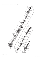
Series SS815, SS825, and SS850 Starters
(SS815 and SS825 shown in full view)
4A
9
15
40
41
18
62
42
31
29
19
35
20
58
37
36
50
34
49
28
37
36
34
35
31
26
45
46
44
54
27
47
56
31A
53
50
33
30
54
28
29
57
25
23
32
33A
27
47
24
21
49
22
44
46
53
26
45
56
33
30
32
24
25
23
22
21
Front End Construction of Series SS850
(Dwg. TPA853-4)
25
26
31
34
31A
35
30
36
4
39
14
24
50
2
23
28
51
25
29
37
4A
3
22
41
49
21
40
46
27
42
9
10
11
10A
12
53
44
45
26
47
8
56
54
6
7
5
57
32
6
33
1
13
15
17
16
20
18
19
61
58
60
59
62
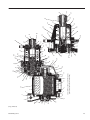
Series SS815 and SS825 Starters Exploded Diagram
(Dwg. TPA778-6)
03531480_ed13
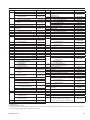
Series SS815 and SS825 Starters Parts List
Item
1
2
3
4
4A
5
† 6
† 7
†• 8
9
† 10
†•10A
†• 11
12
13
14
†• 15
16
17
† 18
19
20
• 21
22
• 23
24
† 25
26
†• 27
Part Description
Motor Housing
with 2-1/2” Tapped Exhaust
with 2-1/2” SAEJ518C
Flanged Exhaust
Motor Housing Cover Assembly
with 1-1/2” Tapped Inlet
with 1-1/2” SAEJ518C Flanged
Inlet
Housing Cover Plug (3)
Motor Housing Cover Cap Screw (4)
Motor Housing Cover Cap Screw
Washer (4)
Cylinder Kit
End Plate Alignment Pin (2)
Cylinder Alignment Pin
Cylinder O-Ring (4)
Rear End Plate
for SS815RB or SS825RC Models
for SS800LB, SS815LB or
SS825LC Models
Rear Rotor Bearing
Rotor Shaft O-Ring
Rear Rotor Bearing O-Ring
Rotor Clamp Nut
Rotor
Rotor Clamp Nut Screw
Vane Packet (set of 5 Vanes)
Front End Plate
Motor Wave Washer (2)
Front Rotor Bearing
Rotor Pinion Retaining Screw
Rotor Pinion
for SS815RB, SS800LB or
SS815LB Models
for SS825RC or
SS825LC Models
Drive Pinion Retaining Screw
for SS815RB or SS825RC
Models
for SS815LB or SS825LC
Models
Drive Pinion (R) Washer
Drive Pinion (L) Washer
Drive Pinion
for SS815GB03R31 Models
for SS815GB03L32 Models
for SS815GB03R91 and
SS825GC03R91 Models
for SS815GB03L92 and
for SS825GC03R25 Models
for SS825GC03R25 Models
for SS825GC03L26 Models
Pinion Spring Sleeve
Pinion Spring
for SS800RB, SS815RB or
SS825RC Models
for SS800LB, SS815LB or
SS825LC Models
Drive Gear Screw
Drive Gear Screw O-Ring
Part Number
SS800-40
SS800-140
SS800-A102
SS800-A202
HSSPPS-3
SS800-25
SS800-26
SS800-K3
510-669A
SS800-99
SS800-67
SS800R-12
SS800L-12
SS800-24
C321-606
HRA20A-990
SS800-65
SS825-53
SS800-63
SS800-42A-5
SS800G-11
SS800-224
SS800-22
SS800-732
SS800B-17
SS825C-17
SS800R-394
SS800L-394
SS800-725
SS800-725-1
SS815R-13-31
SS815L-13-32
SS815R-13-91
SS815L-13-92
SS825R-13-25
SS825L-13-26
SS800-335
SS800R-419
SS800L-419
SS800-179
SS800-176
Item
Part Description
28 Drive Housing Cap Screw (8)
29 Drive Housing Cap Screw
Lock Washer (8)
30 Drive Housing Kit
†• 31
Drive Housing O-Ring
31A
Drive Housing Vent Plug
32 Front Drive Shaft Bearing
for SS815B Models
for SS825C Models
† 33
Drive Housing Seal
† 34 Bulkhead Retainer
35 Bulkhead Kit
†• 36
Outer Bulkhead O-Ring
†• 37
Inner Bulkhead O-Ring
† 39 Clutch Spring Cup Retainer
40 Clutch Spring Cup
† 41 Clutch Spring
42 Clutch Jaw Kit
for SS815RB or
SS825RC Models
for SS815LB or
SS825LC Models
44 Front Drive Gear Bearing
45 Drive Gear Cup
46 Drive Gear Lock Washer
47 Large Drive Shaft Bearing Retainer
49 Piston Kit
†• 50
Piston O-Ring
†• 51
Piston Seal
53 Drive Shaft Kit
for SS815RB or
SS825RC Models
for SS815LB or
SS825LC Models
54 Rear Drive Shaft Bearing Kit
(includes bearing and retainer)
56 Piston Return Spring
57 Piston Return Spring Seat
58 Gear Case
59 Drive Gear Bearing Retainer
60 Drive Gear Shaft Bearing Retainer
† 61 Rear Drive Gear Bearing
62 Drive Gear
for SS815108 or
SS815LB Models
for SS825RC or
SS825LC Models
* Nameplate
* Nameplate Screw (4)
*
Relay Valve
*
*
*
*
*
*
Muffler
Road Splash Deflector
Air Strainer
Lubricator
In-Line Lubricator
Tune-up Kit (includes illustrated parts
6[2], 7, 8, 10, 10A[4], 11, 15, 18, 24, 25,
27, 31, 33, 34, 36, 37, 39, 50, 51, 60 and 61)
Part Number
SS800-744
CE210-605
SS825-K300
SS800-244
P250-546
SS800-363
SS850-363
SS800-273
SS800-181
SS800-K150
SS800-152
SS800-151
SS800-366
SS800-367
SS800-583
SS800R-K587
SS800L-K587
SS800-278
SS800-177
SS800-180
SS800-107
SS800-K703
SS800-337
SS800-273
SS800R-K8
SS800L-K8
SS800-K399
SS800-700
SS800-191
SS800-37
SS800-361
SS800-632
SS800-359
SS815B-9
SS825C-9
SS800-301
R4K-302
SRV150
SS660-A674
SM450-A735
SM450-A267AT
HDL2
NL-24-8
SS800-TK2
* Not Illustrated
† Indicates Tune-up Kit part.
• To keep downtime to a minimum, it is desirable to have on hand certain repair parts. We recommend that you stock one (pair or set) of each part indicated by a bullet (•) for every four tools in service.
03531480_ed13
27
28
31
34
33A
35
30
36
4
25
29
39
14
24
50
2
23
28
51
37
4A
3
22
41
49
21
40
10A
46
27
42
9
10
11
12
53
26
45
44
47
8
56
54
6
7
5
32
6
33
1
13
15
17
16
20
18
19
61
58
60
59
62
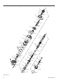
Series SS850 Starters Exploded Diagram
(Dwg. TPA820-3)
03531480_ed13
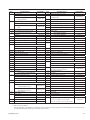
Series SS850 Starters Parts List
Item
1
Part Description
with 2-1/2” Tapped Exhaust
with 2-1/2” SAEJ518C
Flanged Exhaust
2
with 1-1/2” SAEJ518C Flanged
Inlet
4
4A
5
SS800-40
SS800-140
Motor Housing Cover Assembly
with 1-1/2” Tapped Inlet
3
Part Number
Motor Housing
Housing Cover Plug (3)
Motor Housing Cover Cap Screw (4)
Item
Drive Housing Cap Screw (8)
29
Drive Housing Cap Screw
Lock Washer (8)
30
†• 31
SS800-A102
SS800-A202
HSSPPS-3
SS800-25
Motor Housing Cover Cap Screw
Part Description
28
Drive Housing Kit
SS800-744
CE210-605
SS850-K300
Drive Housing O-Ring
SS850-244
32
Front Drive Shaft Bearing
SS850-363
33
Drive Housing Seal
SS800-273
33A
Drive Housing Vent Plug
P250-546
34
Bulkhead Retainer
SS500-181
35
Bulkhead Kit
SS850-K150
†• 36
Outer Bulkhead O-Ring
SS850-152
Inner Bulkhead O-Ring
SS805-151
Washer (4)
SS800-26
†• 37
Cylinder Kit
SS800-K3
† 39
Clutch Spring Cup Retainer
SS850-366
Clutch Spring Cup
SS850-367
SS850-583
†6
End Plate Alignment Pin (2)
510-669A
40
†7
Cylinder Alignment Pin
SS800-99
† 41
Clutch Spring
†• 8
Cylinder O-Ring (4)
SS800-67
42
Clutch Jaw Kit
9
Part Number
Rear End Plate
for SS850RD Models
SS800R-K587
for SS850LD Models
SS800L-K587
for SS850RD Models
SS800R-12
for SS850LD Models
SS800L-12
44
Front Drive Gear Bearing
SS800-278
† 10
Rear Rotor Bearing
SS800-24
45
Drive Gear Cup
SS800-177
†• 10A
Rotor Shaft O-Ring
C321-606
46
Drive Gear Lock Washer
SS800-180
HRA20A-990
47
Large Drive Shaft Bearing Retainer
SS850-107
Piston Kit
SS850-K703
†• 11
Rear Rotor Bearing O-Ring
12
Rotor Clamp Nut
SS800-65
49
13
Rotor
SS825-53
†• 50
Piston O-Ring
SS850-337
14
Rotor Clamp Nut Screw
SS800-63
†• 51
Piston Seal
SS800-273
†• 15
Vane Packet (set of 5 Vanes)
SS800-42A-5
53
Drive Shaft Kit
16
Front End Plate
SS800G-11
for SS850RD Models
17
Motor Wave Washer (2)
SS800-224
for SS850LD Models
Front Rotor Bearing
SS800-22
19
Rotor Pinion Retaining Screw
SS800-732
20
Rotor Pinion
† 18
for SS850RD or SS850LD Models
• 21
22
• 23
Drive Pinion Retaining Screw
(includes bearing and retainer)
SS850L-K8
SS850-K399
56
Piston Return Spring
58
Gear Case
SS850-37
59
Drive Gear Bearing Retainer
SS800-361
Drive Gear Shaft Bearing Retainer
SS800-632
Rear Drive Gear Bearing
SS800-359
SS850-700
SS850R-394
60
for SS850LD Models
SS850L-394
† 61
SS800-725
62
Drive Gear
SS850D-9
*
Nameplate
SS800-301
*
Nameplate Screw (4)
*
Relay Valve
*
Muffler
*
Road Splash Deflector
*
Air Strainer
Drive Pinion Washer
Drive Pinion
SS850FGD09R51 Models
for SS850GD09L52 and
SS850FGD09L51 Models
† 24
Pinion Spring Sleeve
† 25
Pinion Spring
26
Rear Drive Shaft Bearing Kit
for SS850RD Models
for SS850GD09R51 and
†• 27
SS850D-17
54
SS850R-K8
SS850R-13-51
SS850L-13-52
SS800-335
*
In-Line Lubricator
for SS850RD Models
SS850R-419
*
Lubricator
for SS850LD Models
SS850L-419
*
Tune-up Kit (includes illustrated parts
Drive Gear Screw
SS800-179
[2], 7, 8, 10, 10A[4], 11, 15, 18, 24, 25,
Drive Gear Screw O-Ring
SS800-176
27, 31, 33, 34, 36, 37, 39, 50, 51, 60 and 61)
R4K-302
SRV150
SS660-A674
SM450-A735
SM450-A267AT
NL-24-8
HDL2
SS850-TK2
*
Not Illustrated
†
Indicates Tune-up Kit part.
•
To keep downtime to a minimum, it is desirable to have on hand certain repair parts. We recommend that you stock one (pair or set)
of each part indicated by a bullet (•) for every four tools in service.
03531480_ed13
29
Maintenance, Disassembly / Assembly Instructions
WARNING
Always wear eye protection when operating or performing any maintenance on this starter. Always turn off the air supply and
disconnect the air supply hose before installing, removing or adjusting any accessory on this starter or before performing any
maintenance on this starter.
Lubrication
Each time a Series SS815, SS825 or SS850 Starter is disassembled for
maintenance or repair, lubricate the starter as follows:
For temperatures above 32°F (0°C), use a good quality SAE 10
non-detergent motor oil.
For temperatures below 32°F (0°C), use diesel fuel.
1. Lubricate all O-Rings with O-Ring lubricant.
2. Lubricate the Drive Gear (62) with 8 oz. of Ingersoll Rand No.
130 Grease.
3. Lubricate the Vanes (15) with 10W non-detergent oil.
4. Lubricate the inside diameter of the Drive Shaft (53) with
Ingersoll Rand No. 130 Grease.
5. Lubricate the Front Drive Gear Bearing (44) with Ingersoll Rand
No. 130 Grease.
6. Lubricate the pinion end of the Drive Shaft with Ingersoll Rand
No. 11 Grease.
7. Wipe a thin film of Ingersoll Rand No. 130 Grease in the bore of
the Drive Housing (58).
8. Roll the Piston Return Spring (56) in Ingersoll Rand No. 130
grease.
9. Coat the outside of the Piston (49) with Ingersoll Rand No. 130
Grease.
Disassembly
General Information
1. Do not disassemble the starter any further than necessary to
replace worn or damaged parts.
2. When grasping a part in a vise, always use leather-covered or
copper-covered vise jaws to protect the surface of the part and
help prevent distortion. This is particularly true of threaded
members.
3. Do not remove any part which is a press fit in or on a subassembly
unless the removal of that part is necessary for replacement or
repairs.
4. Always have a complete set of seals and O-Rings on hand before
starting any overhaul of a starter. Never reuse old seals or gaskets.
5. Always mark adjacent parts on the Motor Housing Cover (2),
Motor Housing (1), Gear Case (58) and Drive Housing (30) so these
members can be located in the same relative position when the
Starter is reassembled.
Drive Housing
1. Remove the rear Motor Housing Cover Plug (3) from the rear of
the Motor Housing Cover (2).
2. Grasp the Drive Pinion (23) in a vise with the Starter supported on
the workbench.
NOTICE
Models SS815RB, SS825RC and SS850RD have a left-hand
thread; Models SS815LB, SS825LC and SS850LD have a right
hand thread.
3.
4.
5.
6.
Using a wrench, remove the Drive Pinion Retaining Screw (21).
Remove the starter from the vise.
Remove the Drive Pinion Washer (22) and the Drive Pinion (23).
Slide the Pinion Spring Sleeve (24) and the Pinion Spring (25) off
the Drive Shaft.
7. Insert a 3/8” square drive extension through the Motor Housing
Cover to hold the Rotor (13) from turning. Using a 5/16” (8 mm) x
8” (203 mm) long hex wrench inserted into the end of the Drive
Shaft, unscrew the Drive Gear Screw (26).
8. Unscrew and remove the Drive Housing Cap Screws (28) and Lock
Washers (29).
9. Tap the Drive Housing (30) with a plastic hammer to help
dislodge it from the Gear Case (58).
WARNING
Failure to follow this procedure could result in injury to
personnel.
30
10.Place the Drive Housing in an arbor press, piston end up. Apply
pressure to the Piston (49) to compress the Piston Return Spring
(56) before removing the Bulkhead Retainer (34).
11.Using a screwdriver, remove the Bulkhead Retainer. Ease off the
arbor press.
CAUTION
Make sure the tension of the spring pushes the Bulkhead out of
the Drive Housing before removing the Drive Housing from the
arbor press.
12.Remove the Bulkhead (35) from the Piston.
13.Remove the Outer Bulkhead O-Ring (36) and the Inner Bulkhead
O-Ring (37).
14.Slide the Drive Shaft (53) from the Drive Housing.
15.Pull the Piston Return Spring (56) off the Drive Shaft.
NOTICE
Do not remove the Front Drive Shaft Bearing (32) or the Drive
Housing Seal (33) unless replacement is necessary and new
parts are available. The Bearing and/or the Seal will always be
damaged when removed from the Drive Housing.
16.Remove the Piston O-Ring (50) from the Piston.
NOTICE
The following operation will damage the Piston Seal (51).
Therefore, always have a replacement Seal on hand.
17.Insert a large screwdriver blade through the Piston Seal so that
it rests on top of the Clutch Spring Cup. Pry the Seal out of the
Piston.
18.Press the Clutch Spring Cup (40) down and remove the Clutch
Spring Cup Retainer (39).
19.Remove the Clutch spring Cup and Clutch Spring (41).
20.Remove the two Clutch Jaws (42).
21.Remove the Front Drive Gear Bearing (44), Drive Gear Cup (45),
Drive Gear Lock Washer (46), Drive Gear Screw O-Ring (27) and
Drive Gear Screw (26).
22.Using a screwdriver, remove the Large Drive Shaft Bearing
Retainer (47).
23.Press the Rear Drive Shaft Bearing and Drive shaft (53) out of
the Piston. If the Rear Drive Shaft Bearing needs to be replaced,
proceed as follows:
a. Using a small chisel, cut and remove the small drive shaft
bearing retainer on the Drive Shaft.
b. Press the Rear Drive Shaft Bearing (54) off the Drive Shaft.
03531480_ed13
Motor Housing
1. Unscrew and remove the Motor Housing Cover Cap Screw (4).
2. Pull the Motor Housing Cover (2) from the motor Housing (1).
It may be necessary to dislodge the Motor Housing Cover by
tapping it with a plastic hammer.
3. Tap the Gear Case (58) with a plastic hammer to dislodge it from
the Motor Housing.
4. Grasp the Rotor Pinion in a vise and using a wrench, remove the
Rotor Pinion Retaining Screw (19).
5. Remove the Rotor Pinion (20) from the rotor shaft.
6. Slide the Front End Plate (16), Front Rotor Bearing (18) and Motor
Wave Washers (17) off the rotor shaft.
7. Remove the Rotor (13) and Rear End Plate (9) from the Cylinder.
8. Remove and examine each Vane (15). Install a new set of Vanes if
any Vane is cracked, spalled or worn to the extent that its width is
15/16” (24 mm) or less at either end.
9. Grasp the Rotor in a vise. Using a 5/32” (4 mm) hex wrench, loosen
the Rotor Clamp Nut Screw (14). Unscrew and remove the Rotor
Clamp Nut (12).
Assembly
General Instructions
1. Always press on the inner ring of a ball-type bearing when
installing the bearing on a shaft.
2. Always press on the outer ring of a ball-type bearing when
pressing the bearing into a bearing recess.
3. Whenever grasping a starter or part in a vise, always use
leather-covered or copper-covered vise jaws. Take extra care with
threaded parts or housings.
4. Except for bearings, always clean every part and wipe every part
with a thin film of oil before installation.
5. Check every bearing for roughness. If an open bearing must be
cleaned, wash it thoroughly in a suitable cleaning solution and
dry with a clean cloth. Sealed or shielded bearings should
never be cleaned. Work grease thoroughly into every open
bearing before installation.
6. Apply a film of O-Ring lubricant to all O-Rings before final
assembly.
Gear Case
1. Place the Drive Gear Bearing Retainer (59) over the rear end of
the Drive Gear.
2. Using an arbor press, press the Rear Drive Gear Bearing (61) onto
the rear end of the Drive Gear.
3. Using retaining ring pliers, install the Drive Gear Shaft Bearing
Retainer (60).
4. Position the Gear Case on a workbench. Using a plastic hammer,
seat the Rear Drive Gear Bearing into the Gear Case by tapping
the opposite end of the Drive Gear.
5. Using retaining ring pliers and working through the access holes
in the gear web, install the Drive Gear Bearing Retainer (59).
6. Lubricate the Drive Gear with approximately 8 oz. (240 mL) of
Ingersoll Rand No. 130 Grease.
Motor Housing
1. Clamp the Rotor in a vise threaded end up.
2. Install the Rear Rotor Bearing (10) into the Rear End Plate.
3. Using O-Ring lubricant, lubricate and install the Small Rear Rotor
Bearing O-Ring (10A) onto the rotor shaft until it butts against the
rotor shaft shoulder.
4. Install the Rear End Plate (9), bearing end up, onto the rotor shaft.
5. Screw the Rotor Clamp Nut (12) onto the rotor shaft with the
shoulder toward the bearing. Tighten the nut until there is .001”
(.02 mm) to .003” (.07 mm) clearance between the Rear End Plate
and Rotor.
6. Using a 5/32” (4 mm) hex wrench, tighten the Rotor Clamp Nut
Screw (14). After tapping the End Plate away from the rotor face
with a plastic hammer, recheck the clearance between the Rear
End Plate and Rotor.
03531480_ed13
10. Remove the Large Rear Rotor Bearing O-Ring (11).
11. Remove the Rear End Plate (9) from the rotor shaft.
12. Remove the Small Rear Rotor Bearing O-Ring (10A) from the rotor
shaft.
13. If the Rear Rotor Bearing (10) needs to be replaced, remove it from
the Rear End Plate.
14. Push the Cylinder (5) out of the Motor Housing.
15. Remove the Cylinder O-Rings (8) from the Cylinder.
Gear Case
1. Place the Gear Case (58) on a workbench.
2. Using retaining ring pliers and working through the access holes
in the gear web, remove the Drive Gear Bearing Retainer (59).
3. Pull the Drive Gear (62) out of the Gear Case.
4. Do not disassemble the Drive Gear of Series SS815, SS825 or
SS850. If the Drive Gear is defective, install a new or factory rebuilt
unit.
5. Using a retaining ring pliers, remove the Drive Gear Shaft Bearing
Retainer (60).
6. Remove the Rear Drive Gear Bearing (61) from the Drive Gear.
7. Check the two End Plate Alignment Pins (6). If they are bent or
broken, remove them from the Cylinder and press in a new pin
or pins.
8. Check the Cylinder Alignment Pin (7). If it is bent or broken,
remove it from the Cylinder and press in a new pin.
9. Using O-Ring lubricant, lubricate and install the two inside
Cylinder O-Rings (8).
10. Position the Motor Housing (1) vertically, on two blocks of wood,
locating slot up.
11. Using a plastic hammer, tap the Cylinder (5) into the Motor
Housing making sure the Cylinder Alignment Pin (7) seats into the
slot of the Motor Housing.
12. Using O-Ring lubricant, lubricate and install the two outside
Cylinder O-Rings (8).
13. For Right-Hand Rotation Starter: Insert the Rotor (13) into the
Cylinder, pinion end toward the Cylinder Alignment Pin.
NOTICE
Make sure the protruding End Plate Alignment Pin (6) in the
Cylinder aligns with the dowel hole in the Rear End Plate (9)
numbered SS800R-12. Make sure the air ports of both the
Cylinder and the Rear End Plate align.
For Left-Hand Rotation Starter:
Insert the Rotor (13) into the Cylinder, pinion end away from the
Cylinder Alignment Pin.
NOTICE
Make sure the protruding End Plate Alignment Pin (6) in the
Cylinder aligns with the dowel hole in the Rear End Plate (9)
numbered SS800L-12. Make sure the air ports of both the
Cylinder and the Rear End Plate align.
14.Lightly lubricate each Vane (15) and insert one in each of the
rotor vane slots.
15.Slide the Front End Plate (16) over the pinion end of the Rotor. The
other protruding End Plate Alignment Pin (6) in the face of the
Cylinder should align with the dowel hole in the Front End Plate.
16.Insert the two Motor Wave Washers (17) into the Front End Plate
well.
17.Install the Front Rotor Bearing (18) into the Front End Plate well.
18.Install the Rotor Pinion (20) on the rotor shaft so that the lugs on
the Pinion engage those on the shaft.
19.Screw the Rotor Pinion Retaining Screw (19) into the rotor shaft
and tighten to 90 ft-lb (122 Nm) torque.
20.Using O-Ring lubricant, lubricate and install the Rear Rotor
Bearing O-Ring (11) onto the Rear Rotor Bearing.
21. Check freeness of the motor by turning the Rotor Pinion. If necessary,
tap the Front End Plate with a soft hammer to align the motor.
31
22.Align the punch marks on the Gear Case (58), Motor Housing (1)
and Motor Housing Cover (2) and assemble as follows:
a. Grasp the Gear Case (58) in a vise by the Drive Gear Shaft.
b. Insert the pinion end of the motor into the Gear Case.Using a
soft hammer, tap the Motor Housing (1) until it seats.
c. Position the Motor Housing Cover (2) on the Motor Housing.
Using a soft hammer, tap the Motor Housing Cover until it is
seated on the Motor Housing.
NOTICE
Screw a 12” (305 mm) piece of 1-1/2” (38 mm) pipe into the air
inlet to act as a handle to help align the Motor Housing with the
Motor Housing Cover and Gear Case.
16.Slide the Piston Return Spring (56) onto the Drive Shaft and snap
it into the front of the Piston so that it is against the Large Drive
Shaft Bearing Retainer (47).
17.Lubricate and insert the assembled Drive Shaft into the Drive
Housing.
18.Using O-Ring lubricant, lubricate and install the Outer Bulkhead
O-Ring (36) and the Inner Bulkhead O-Ring (37) on the
Bulkhead (35).
19.Slide the Bulkhead onto the Piston.
20.With the Drive Housing in the arbor press, press down on the rear
face of the Piston.
NOTICE
d. Lubricate the threads and install the Motor Housing Cover
Cap Screws (4) and Lock Washers (4A), alternately tightening
each a little at a time to a final torque of 60 ft-lb (81.4 Nm).
24.Install two of the Housing Cover Plugs (3) into the Motor Housing
Cover inlet boss and tighten securely.
Feel the underside of the Drive Housing to make sure the Drive
Shaft passes through the Bearing.
Drive Housing
Make sure the Bulkhead Retainer is properly seated in the Motor
Housing groove before easing off the arbor press.
1. Press the Rear Drive Short Bearing (54) onto the Drive Shaft.
2. Slide the small bearing retainer, convex side first, onto the Drive
Shaft. Press it into position in accordance with the instructions
packaged with the new Retainer.
3. Assemble the Drive Gear Screw (26), Drive Gear Lock Washer (46),
Drive Gear Cup (45) and Drive Gear Screw O-Ring (27).
4. Grasp the Drive Shaft (53) in a vise, pinion end down. Place
assembled Drive Shaft Screw Unit into the Drive Shaft, screw and
head down. Lubricate the inside diameter of the Drive Shaft with
Ingersoll Rand No. 130 Grease.
5. Slide the Front Drive Gear Bearing (44) into the Drive Shaft.
6. Lubricate with Ingersoll Rand No. 130 Grease and install the
Driving Clutch Jaw teeth facing up and Driven Clutch Jaw teeth
facing down into the Drive Shaft.
7. Insert the Clutch Spring (41) into the Drive Shaft.
8. Insert the Clutch Spring Cup (40) into the Drive Shaft.
9. Press the inserted parts into the Drive Shaft, and install the Clutch
Spring Cup Retainer (39).
10. Using an arbor press, press the Piston Seal (51), cover side out,
into the Piston until it is flush with the piston face.
11. Install the Piston (49) onto the Drive Shaft until the Rear Drive
Shaft Bearing seats into the Piston.
12. Using a thin flat blade screwdriver to assist in this operation, coil
the Large Drive Shaft Bearing Retainer (47) into the groove of the
Piston to retain the outer race of the Drive Shaft Bearing.
13. Lubricate the Piston O-Ring (50) and install it in the groove of
the Piston.
14. Position the Drive Housing in an arbor press, pinion end down
and install the Drive Housing Seal (33) into the Drive Housing.
NOTICE
Press the Seal into the Drive Housing so that the lip of the Seal
faces towards the Drive Pinion.
15.Using a sleeve that contacts the outer race of the Front Drive
Shaft Bearing (32), press the Bearing into the Drive Housing until
it seats. For Models SS815 and SS825, drop the Piston Return
Spring Seat (57) on top of the Front Drive Shaft Bearing.
Using a screwdriver, install the Bulkhead Retainer (34).
WARNING
21.Remove the Drive Housing from the arbor press.
22.Using O-Ring lubricant, lubricate and install the Drive Housing
O-Ring (31) in the groove of the Drive Housing.
23.Position the assembled Motor Housing and Gear Case on a
workbench. Assembled unit must be upright to accept the Drive
Housing.
24.Carefully position the assembled Drive Housing (30) on to the
Gear Case so as not to damage the Piston Seal. Align the punch
marks of the Gear Case and Drive Housing.
25.Install the Drive Housing Cap Screw Lock Washers (29) and the
Drive Housing Cap Screws (28) and tighten to 28 ft-lb (38 Nm)
torque.
26.Insert a 3/8” (10 mm) square drive extension bar through the hole
in the Motor Housing Cover to prevent the Rotor from turning.
Using a 5/16” (8 mm) x 8” (203 mm) long hex wrench inserted into
the end of the Drive Shaft, tighten the Drive Gear Screw (26) to 29
ft-lb (39.3 Nm) torque.
27.Using Ingersoll Rand No. 11 Grease, Lubricate and slide the
Pinion Spring (25) and the Pinion Spring Sleeve (24) over the
Pinion end of the Drive Shaft.
28.Lubricate the pinion end of the Drive Shaft with Ingersoll Rand
No. 11 Grease and install the Drive Pinion (23).
29.Grasp the Drive Pinion in a vise with the Starter supported on a
workbench.
30.Place the Drive Pinion Washer (22) onto the Drive Pinion
Retaining Screw (21). Install the Drive Pinion Retaining Screw into
the end of the Drive Shaft and tighten it to 80 ft-lb (108.5 Nm)
torque for SS815 and SS825 Starters, and 125 ft-lb (169.5 Nm)
torque for SS850 Starters.
NOTICE
Models SS815RB, SS825RC and SS850RD have a left-hand thread;
Models SS815LB, SS825LC and SS850LD have a right-hand thread.
Remove the Starter from the vise.
31.Install the rear Motor Housing Cover Plug (3) and tighten securely.
Test and Inspection Procedure
1. Clutch Ratcheting: Turn the Drive Shaft Pinion (23) by hand in the
direction of Starter rotation. The clutch should ratchet smoothly
with a slight clicking action.
2. Motor and Gearing Freeness: Turn the Drive Shaft Pinion (23)
opposite the direction of Starter rotation. The Drive Shaft Pinion
should turn by hand.
3. Pinion Engagement: Apply 50 psig (3.4 bar/345 kPa) pressure
to the engagement “In” Port. Drive Shaft Pinion (23) should move
outward and air or gas should escape from the “Out” Port. Plug the
“Out” Port and apply 150 psig (10.3 bar/I 034 kPa) pressure to the
“In” Port. Check and make sure no air or gas is escaping. Measure the
dimension from the face of the Drive Shaft Pinion (23) to the face
of the mounting flange. It should be 2-23/32” (69.0 + 2.0 mm) for
32
Models SS815, SS825 and 8-3/4” (222 + 2.0 mm) for Model SS850.
Remove the pressure from the “In” Port. Measure the distance from
the face of the Drive Shaft Pinion (23) to the face of the mounting
flange. It should be 1-25/32” 45.0 + 2.0 mm) for Models SS815,
SS825 and 7-3/32” (180 + 2.0 mm) for Model SS850.
4. Motor Vane Action: Apply 90 psig (6.2 bar/620 kPa) pressure
using a 3/8” (9 mm) supply line to the inlet of the motor. Starter
should run smoothly.
5. Motor Seals: Plug the exhaust and apply 20 psig
6. (1.4 bar/138 kPa) pressure to the inlet of the motor. Immerse the
Starter for 30 seconds in a nonflammable solvent. If the Starter is
properly sealed, no bubbles, will appear.
03531480_ed13
Troubleshooting Guide
Trouble
Motor will not run
No air supply.
Probable Cause
Solution
Check for blockage or damage to air supply lines or tank.
Damaged Motor Assembly
Inspect Motor Assembly and power train and repair or replace if
necessary.
Foreign material in Motor and/or piping
Blocked exhaust system.
Defective Control Valve or Relay Valve.
Low air pressure to Starter.
Restricted air supply line.
Relay Valve malfunctioning.
Exhaust flow restricted.
Loss of Power
Damaged Motor Assembly.
Foreign material in Starter Drive.
Damaged or worn Drive parts.
Inadequate lubrication.
Starter drive does
not engage ring
gear or engages and
disengages ring gear
very slowly.
WARNING
Clogged control hoses.
Clogged or faulty Control Valve.
Broken Clutch Jaws or other parts.
Motor runs, pinion
engages but does not
rotate.
Excessive butt
engagements.
Remove Motor Assembly and/or piping and remove blockage.
Remove Housing Exhaust Cover and check for blockage.
Replace Control Valve or Relay Valve.
Check air supply.
Check for blockage or damage to air lines.
Clean or replace lines or Relay Valve. Lube Relay Valve.
Check for blocked or damaged piping. Clean or replace piping. Check
for dirt or foreign material and clean or remove. Check for ice build-up.
Melt ice and reduce moisture build-up to Starter.
Replace Motor Assembly.
Foreign material in Starter Drive.
Check Drive components and replace if necessary.
Check the lubricator, inlet hose, fitting, and oil supply hose to make
sure they are vacuum tight and free of leaks. Tighten all joints and
replace lubricator if necessary.
Remove the control hoses attached to the Drive Housing and clean
them by blowing compressed air through them.
Broken Shaft, Gearing, or Clutch Jaws.
Dry Drive Pinion Spline.
Firmly secure the hose end before turning on the air. Make certain
no one is in line with the discharge end of the control hose.
Remove and inspect the Control Valve or install a new Control Valve
if necessary.
Disassemble Drive Housing and replace broken parts.
Disassemble Drive Housing and replace broken parts.
Remove Drive Pinion and lubricate the Drive Pinion and the helical
spline of the Drive Shaft. Refer to Disassembly of the Drive Housing.
Parts and Maintenance
NOTICE
The use of other than genuine Ingersoll Rand replacement parts may result in safety hazards, decreased motor performance, and
increased maintenance, and may invalidate all warranties.
Ingersoll Rand is not responsible for customer modification of Starters for applications on which Ingersoll Rand was not consulted.
Repairs should be made only by authorized trained personnel. Consult your nearest Ingersoll Rand Authorized Service center.
When the life of the Starters has expired, it is recommended that the Starters be disassembled, degreased and parts be separated by material so
that they can be recycled.
Manuals can be downloaded from ingersollrandproducts.com.
Refer all communications to the nearest Ingersoll Rand Office or Distributor.
03531480_ed13
33
Notes:
Notes:
ingersollrandproducts.com
© 2014 Ingersoll Rand