1
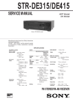
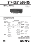
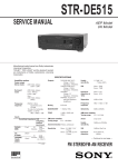
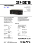
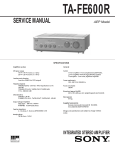
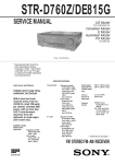
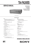
STR-DE135
SERVICE MANUAL
US Model
AEP Model
UK Model
Photo: US model
SPECIFICATIONS
Audio power specifications (US model)
POWER OUTPUT AND TOTAL HARMONIC DISTORTION
With 8-ohm load, both channels driven, from 20 – 20,000 Hz,
rated 100 watts per channel minimum RMS power, with no
more than 0.09 % total harmonic distortion from 250 milliwatts to rated output.
Amplifier section
Stereo mode
Frequency response
(8 ohms at 20 Hz – 20 kHz less than
0.09 % total harmonic distortion)
100 W + 100 W (US model)
(DIN 1 kHz, 4 ohms)
60 W + 60 W (AEP, UK models)
TV/SAT, CD, MD/TAPE, VIDEO
(US model)
TV/LD, CD, MD/TAPE, VIDEO
(AEP, UK models)
10 Hz – 50 Hz ± 1 dB
Muting
BASS BOOST
TONE
Tuner Section
FM stereo, FM/AM superheterodyne tuner
FM tuner section
Tuning range
Antenna terminals
Intermediate frequency
Sensitivity
Usable sensitivity
S/N
Inputs
CD,
MD/TAPE,
TV/SAT,
VIDEO
CD,
MD/TAPE,
TV/LD,
VIDEO
Sensitivity
Impedance
S/N
150 mV
50
kilohms
78 dB
Sensitivity
Impedance
150 mV
50
kilohms
(US model)
S/N
78 dB
(AEP, UK models)
outputs
MICROFILM
MD/TAPE REC OUT:
Voltage: 150 mV,
impedance: 10 kilohms
VIDEO AUDIO OUT:
Voltage: 150 mV,
impedance: 10 kilohms
PHONES: Accepts low and high
impedance headphones
Full mute
+ 10 dB at 70 Hz
± 8 dB at 100 Hz and 10 kHz
Harmonic distortion at 1 kHz
Separation
Frequency response
Selectivity
AM tuner section
Tuning range
87.5 – 108.0 MHz
75 ohms, unbalanced
10.7 MHz
Mono: 18.3 dBf, 4.5 µV
Stereo: 38.3 dBf, 45 µV (US model)
Mono: 18.3 dBf, 2.2 µV/75 ohms
Stereo: 38.3 dBf, 22.5 µV/75 ohms
(AEP, UK models)
11.2 dBf, 2 µV (IHF) (US model)
11.2 dBf, 1 µV/75 ohms (IHF)
(AEP, UK models)
Mono: 76 dB
Stereo: 70 dB
Mono: 0.3 %
Stereo: 0.5 %
45 dB at 1kHz
30 Hz – 15 kHz +0.5
–2 dB
60 dB at 400 kHz
10 kHz interval*
530 – 1710 kHz
9 kHz interval
531 – 1710 kHz (US model)
531 – 1602 kHz (AEP, UK models)
– Continued on next page –
FM STEREO/FM-AM-RECEIVER
Antenna
Intermediate frequency
Usable sensitivity
S/N
Harmonic distortion
Selectivity
TABLE OF CONTENTS
Loop antenna
450 kHz
50 dB/m (at 1,000 kHz)
54 dB (at 50 mV/m)
0.5 % (50 mV/m, 400Hz)
At 10 kHz: 40 dB
At 9 kHz: 35 dB (US model)
35 dB (AEP, UK models)
* You can change the AM tuning interval between 9 kHz and 10kHz.
After tuning in any AM station, turn off the receiver. Hold down the
PRESET TUNING + button and press the 1/u (power) button. All preset stations will be erased when you change the interval. To reset the
interval, repeat the procedure.
(US model)
General
System
Tuner section:
PLL quartz-locked digital
synthesizer system
Preamplifier section:
Low-noise NF type equalizer
Power amplifier section:
Pure-complementary SEPP
Power requirements
120 V AC, 60 Hz (US model)
230 V AC, 50/60 Hz
(AEP, UK models)
Power consumption
155 W (US model)
135 W (AEP, UK models)
AC outlets
1 switched, total 120 W/1A Max
(US, UK models)
switch 100 W max (AEP model)
Dimensions
430 × 144 × 306 mm
(17 × 56/8 × 124/8 inches)
Mass (Approx.)
8.1 kg (17 lb 13 oz) (US model)
6.7 kg (AEP, UK models)
Supplied accessories
FM wire antenna (1)
AM loop antenna (1)
Remote commander (remote) (1)
Size AA (R6) batteries (2)
Specifications indicated are measured at 230 V AC, 50Hz.
(AEP, UK models)
1.
SERVICING NOTES ............................................... 3
2.
GENERAL ................................................................... 4
3.
DISASSEMBLY ......................................................... 5
4.
TEST MODE ............................................................... 7
5.
DIAGRAMS
5-1. Note for Printed Wiring Boards and
Schematic Diagrams .......................................................
5-2. Printed Wiring Board – MAIN Board – ........................
5-3. Schematic Diagram – MAIN Board (1/2) – ..................
5-4. Printed Wiring Boards
– DISPLAY Board/KEY Board/VOLUME Board/
TONE Board/POWER SWITCH Board – ...................
5-5. Schematic Diagram
– PANEL Section – .........................................................
5-6. Printed Wiring Boards
– PANEL Section – .........................................................
5-7. Schematic Diagram
– MAIN Board (2/2)/SPK SWITCH Board/
SECONDARY Board/PRIMARY Board/
STANDBY TRANS Board – .......................................
5-8. IC Pin Function Description ...........................................
9
11
13
15
19
23
25
26
6.
EXPLODED VIEWS ................................................ 28
7.
ELECTRICAL PARTS LIST ............................... 31
Design and specifications are subject to change without notice.
SAFETY-RELATED COMPONENT WARNING!!
COMPONENTS IDENTIFIED BY MARK ! OR DOTTED
LINE WITH MARK ! ON THE SCHEMATIC DIAGRAMS
AND IN THE PARTS LIST ARE CRITICAL TO SAFE
OPERATION. REPLACE THESE COMPONENTS WITH
SONY PARTS WHOSE PART NUMBERS APPEAR AS
SHOWN IN THIS MANUAL OR IN SUPPLEMENTS PUBLISHED BY SONY.
–2–
SECTION 1
SERVICING NOTES
MODEL IDENTIFICATION
SAFETY CHECK-OUT
After correcting the original service problem, perform the following safety check before releasing the set to the customer:
Check the antenna terminals, metal trim, “metallized” knobs,
screws, and all other exposed metal parts for AC leakage.
Check leakage as described below.
– Rear view –
12345
PART No.
MODEL
PART No.
US model
4-216-802-0π
AEP model
4-216-802-1π
UK model
4-216-802-2π
LEAKAGE TEST
The AC leakage from any exposed metal part to earth ground and
from all exposed metal parts to any exposed metal part having a
return to chassis, must not exceed 0.5 mA (500 microampers.).
Leakage current can be measured by any one of three methods.
1. A commercial leakage tester, such as the Simpson 229 or RCA
WT-540A. Follow the manufacturers’ instructions to use these
instruments.
2. A battery-operated AC milliammeter. The Data Precision 245
digital multimeter is suitable for this job.
3. Measuring the voltage drop across a resistor by means of a
VOM or battery-operated AC voltmeter. The “limit” indication is 0.75 V, so analog meters must have an accurate lowvoltage scale. The Simpson 250 and Sanwa SH-63Trd are examples of a passive VOM that is suitable. Nearly all battery
operated digital multimeters that have a 2 V AC range are suitable. (See Fig. A)
To Exposed Metal
Parts on Set
0.15 µF
1.5 k Ω
AC
voltmeter
(0.75 V)
Earth Ground
Fig. A. Using an AC voltmeter to check AC leakage.
–3–
SECTION 2
GENERAL
Location of controls
• Front view –
1
!™
2 345678 9 0 !¡
@¢
!£
@∞
!¢
@§
!∞ !§!¶ !• !ª
1 I/u button
@™
8 FM button
2 TUNING +, – buttons
(US model)
TUNING/CHAR +, – buttons
(AEP, UK models)
3 NAME button
@º @¡
(AEP, UK models)
4 PRESET/TUNING +, – buttons
(US model)
@£
(US model)
FM/AM button
(AEP, UK models)
!• MEMORY button
MEMORY/ENTER button
9 VIDEO button
(AEP, UK models)
0 TV/SAT button
TV/LD button
(US model)
(US model)
(AEP, UK models)
!ª FM MODE button
@º TUNER button
!¡ MD/TAPE button
@¡ CD button
!™ BASS BOOST button and indicator
@™ VOLUME control
!£ SPEAKERS A, B ON/OFF buttons
@£ MUTING button and indicator
(AEP, UK models)
!¢ PHONES jack
@¢ TREBLE control
5 DISPLAY button
(AEP, UK models)
!∞ SHIFT button
@∞ BASS control
6 RDS PTY button
(AEP, UK models)
!§ Numeric buttons
@§ BALANCE control
(US model)
!¶ DIRECT button
PRESET/PTY SELECT +, – buttons
7 AM button
RDS EON button (AEP, UK models)
• Rear view –
–4–
SECTION 3
DISASSEMBLY
Note: Follow the disassembly procedure in the numerical order given.
CASE
1 tapping screw
1 two tapping screws
2 case
1 two tapping screws
FRONT PANEL SECTION
3 screw
(BVTP3 × 8)
2 three connectors
(CNP702 – 704)
4 claw
1 two flat wires
(CNS204, CNP404)
5 front panel
section
4 claw
3 four screws
(BVTP3 × 8)
–5–
REAR PANEL SECTION
4 rear panel section
2 connector
(CNP901)
3 four screws
(BVTP3 × 8)
3 six screws
(BVTP3 × 8)
1 flat wire
(CNS205)
MAIN BOARD
2 connector
(CNP702)
3 three screws
(BVTP3 × 8)
2 connector
(CNS802)
3 three screws
(BVTP3 × 8)
5 MAIN board
2 two connectors
(CNP703, 704)
1 two flat wires
(CNS204, CNP404)
2 connector
(CNP801)
4 PC board holder
–6–
SECTION 4
TEST MODE
Fluorescent Indicator Tube Test Mode
All fluorescent segments are tested. When this test is activated, all
segments turn on at the same time, then each segment turns on one
after another.
Procedure:
1. While pressing two buttons of [TV/SAT] (US model)* and
[DIRECT] simultaneously, press the 1/u button to turn the
power ON.
2. All segments turn on at the same time, then each segment turns
on one after another.
3. The message “FINISH” appears when this test is complete.
*) AEP, UK models are [TV/LD]
AUTO-BETICAL Check Mode (AEP, UK models)
To auto-scanning and memories of RDS station.
Procedure:
1. While pressing the [MEMORY/ENTER] button, press the
1/u button to turn the power ON.
2. The message “AUTO BET” appears and each function is selected one after another.
AM Tuning Interval Selection Mode (US model)
Either 9 kHz step or 10 kHz step can be selected for the AM tuning interval.
Procedure:
1. Set the FUNCTION to AM.
2. Press the 1/u button to turn the power OFF.
3. While pressing the [TUNING+] button, press the 1/u button to
turn the power ON.
4. Either the message “9k STEP” or “10k STEP” appears.
5. Select the desired step.
Software Version Display Mode
The software version is displayed.
Procedure:
1. While pressing two the buttons of [MD/TAPE] and [DIRECT]
simultaneously, press the 1/u button to turn the power ON.
2. The software version is displayed.
–7–
SECTION 5
DIAGRAMS
• Circuit Boards Location
SECONDARY board
PRIMARY board
STANDBY TRANS
board
POWER SWITCH board
DISPLAY board
MAIN board
SPK SWITCH
board
VOLUME board
KEY board
TONE board
–8–
5-1.
NOTES FOR PRINTED WIRING BOARDS AND SCHEMATIC DIAGRAMS
Note on Printed Wiring Board:
• X : parts extracted from the component side.
• b : Pattern from the side which enables seeing.
(The other layers' patterns are not indicated.)
• Indication of transistor.
Q
B C
E
Note on Schematic Diagram:
• All capacitors are in µF unless otherwise noted. pF: µµF
50 WV or less are not indicated except for electrolytics
and tantalums.
• All resistors are in Ω and 1/4 W or less unless otherwise
specified.
¢
•
: internal component.
• 2 : nonflammable resistor.
• C : panel designation.
B
C
E
These are omitted.
– DISPLAY Board –
1 IC1 !¢ (XO)
1 IC201 #∞ (X2)
1.6 Vp-p
5.4 Vp-p
Note: The components identified by mark ! or dotted line
with mark ! are critical for safety.
Replace only with part number specified.
These are omitted.
Q
• Waveforms
– MAIN Board –
• U : B+ Line.
• V : B– Line.
• Voltages and waveforms are dc with respect to ground
under no-signal (detuned) conditions.
no mark : FM
• Voltages are taken with a VOM (Input impedance 10 MΩ).
Voltage variations may be noted due to normal production tolerances.
• Waveforms are taken with a oscilloscope.
Voltage variations may be noted due to normal production tolerances.
• Circled numbers refer to waveforms.
• Signal path.
F : FM
–9–
4.33 MHz
4.19 MHz
– 10 –
STR-DE135
5-2. PRINTED WIRING BOARD – MAIN Board –
• See page 8 for Circuit Boards Location.
(Page 24)
(Page
23)
(Page
23)
(Page
23)
• Semiconductor
Location
Ref. No.
Location
D421
D710
D721
D722
D723
D724
D801
D802
D804
D820
D821
D822
D823
D951
D952
D953
D954
D955
D956
F-5
I-11
H-5
H-5
H-6
I-5
I-7
D-12
I-7
C-12
C-12
C-12
C-12
A-10
A-10
A-10
A-10
A-10
A-10
IC1
IC401
IC403
IC701
IC801
IC802
IC803
IC804
IC950
D-1
C-4
E-3
E-7
C-6
C-6
B-7
C-7
A-7
Q303
Q304
Q401
Q402
Q451
Q452
Q701
Q702
Q703
Q704
Q710
Q720
Q721
Q722
Q723
Q751
Q752
Q753
Q754
Q770
Q801
Q802
Q951
E-3
D-3
F-5
F-5
E-5
F-5
G-8
G-8
H-8
F-8
I-12
G-7
I-5
H-6
I-5
C-8
D-8
E-8
C-8
B-7
H-7
C-13
A-7
(AEP,UK)
C757
(AEP,UK)
C707
(Page 23)
(Page 17)
– 11 –
(Page 15)
– 12 –
STR-DE135
5-3.
SCHEMATIC DIAGRAM – MAIN Board (1/2) – • See page 10 for Waveform.
• See page 21 for IC Block Diagrams.
(Page
25)
(Page 20)
(Page
25)
(Page
25)
The components identified by mark ! or dotted
line with mark ! are critical for safety.
Replace only with part number specified.
(Page 19)
– 13 –
– 14 –
STR-DE135
5-4.
PRINTED WIRING BOARDS – PANEL Section – • See page 8 for Circuit Boards Location.
(Page 11)
• Semiconductor
Location
Ref. No.
Location
D201
D202
D203
D204
D223
D224
A-3
A-3
A-3
B-3
A-10
A-10
IC201
IC202
IC203
B-6
A-1
B-11
Q201
Q202
B-3
B-3
(Page
17)
(Page 17)
– 15 –
– 16 –
STR-DE135
(Page 11)
(Page 17)
(Page 18)
(Page 15)
(Page 16)
– 17 –
– 18 –
STR-DE135
5-5.
SCHEMATIC DIAGRAM – PANEL Section – • See page 10 for Waveform. • See page 22 for IC Block Diagram.
(Page 14)
100k
(Page
13)
The components identified by mark ! or dotted
line with mark ! are critical for safety.
Replace only with part number specified.
– 19 –
– 20 –
STR-DE135
• IC Block Diagrams
– MAIN Board –
– DISPLAY Board –
IC1
IC202 BA6208
RDCL
TS7
OSCO
OSCI
VDDD
VSSD
TEST
TSTLD
BU1922 (AEP, UK models)
16
15
14
13
12
11
10
9
TEST LOGIC AND OUTPUT
SELECTOR SWITCH
SWITCH
MOTOR
DRIVE
SWITCH
MOTOR
DRIVE
3
4
5
6
7
8
9
Vcc
OUTPUT 2
OUTPUT1
NC
CLOCKED
COMPARATOR
2
GND
CONTAS LOOP
VARIABLE AND
FIXED DIVIDER
1
NC
BIPHASE
SYMBOL
DECODER
ANTIALIASING
FILTER
INPUT 2
DEFFERENTIAL
DECODER
57kHz
BANDPASS
(8th ORDER)
RECONSTRUCTION
FILTER
INPUT 1
OSCILLATOR
AND
DIVIDER
NC
REG
QUALITY BIT
GENERATOR
CLOCK REGENERATION
AND SYNC
VP1
3
4
5
6
OUT
IN
OUT
RDDA
Vref
MUX
VDDA
VSSA
1
30
2
29 IN
3
28
4
27 OUT
5
26
CR
1
VSC
2
–
6
25 IN
7
24
8
23 OUT
9
22
10
21
VREF
8
RESET
7
VSA
6
VSB/SESIN
5
V+
+
+ –
OUTC
3
GND
4
IN
IN
OUT
11
VEE
12
20 OUT
LEVEL SHIFT
LATCH
CONTROL
CE 13
DI
8
IC950 NJM2103D
IC401 LC78212
IN
7
SCOUT
2
CIN
1
QUAL
REFERENCE
VOLTAGE
14
CL 15
19 VDD
Q
18 RESET
R
S
+
–
+ –
17 S
SHIFT RESISTOR
16 VSS
IC701 µPC2581V
BIAS CIRCUIT
PROTECTOR
PRE
DRIVE
2
3
4
5
6
7
8
9
10
11
12
– VOUT1
COMP1
MF1
IN1
GND
IN2
NF2
COMP2
– VOUT2
+ VOUT2
13 14 15
VCC2
VEE
1
+ VOUT1
DRIVE
VCC1
PRE
DRIVE
DRIVE
MUTE
REG
– 21 –
– 22 –
STR-DE135
5-6.
PRINTED WIRING BOARDS – SPK SWITCH Board/SECONDARY Board/PRIMARY Board/STANDBY TRANS Board –
• See page 8 for Circuit Boards Location.
(Page 12)
(Page 12)
(AEP)
(Page 12)
(Page 12)
(Page 23)
(Page 12)
(Page 24)
– 23 –
– 24 –
STR-DE135
5-7.
SCHEMATIC DIAGRAM – MAIN Board (2/2)/SPK SWITCH Board/SECONDARY Board/
PRIMARY Board/STANDBY TRANS Board –
R742
1.2k 1/2W
R792
1.2k 1/2W
(Page 14)
(Page 14)
(Page 14)
The components identified by mark ! or dotted
line with mark ! are critical for safety.
Replace only with part number specified.
– 25 –
5-8.
IC PIN FUNCTION DESCRIPTION
• DISPLAY BOARD IC201 µPD78044FGF-115-3B9 (SYSTEM CONTROLLER, FL DRIVER)
Pin No.
Pin Name
I/O
Description
1 to 7
DIG7 to DIG1
O
Digit drive signal output to the fluorescent indicator tube (FL201)
8
VDD
—
Power supply terminal (+5V)
9
S.CLK
O
Serial data transfer clock signal output to the LC78212 (IC401), PLL IC on FM/AM tuner pack
“L” active
10
S.DATA
O
Serial data output to the LC78212 (IC401), PLL IC on FM/AM tuner pack
11
PLL.DATA
I
Serial data input from the PLL IC on FM/AM tuner pack
12
S.CE (LC7822)
O
Serial chip enable signal output to the LC78212 (IC401), PLL IC on FM/AM tuner pack
“H” active
13
S.CE (LV1010)
O
Serial chip enable signal output terminal
14
REAR-RY
O
Relay drive signal output for the rear side speaker
15
BRIDGE
O
Bridgeable relay drive signal output terminal
16
PROTECT
I
Over load detect signal input from the protect circuit
17
RESET
I
System reset signal input from the reset signal generator (IC950, Q201) “L”: reset
For several hundreds msec. after the power supply rises, “L” is input, then it changes to “H”
18
AUTO-STOP
I
Tuned display detection signal input from the FM/AM tuner pack
19
STEREO-IN
I
Stereo detection signal input from the FM/AM tuner pack
20
AVSS
—
Ground terminal (for A/D converter analog system)
21
SP-RY
O
Relay drive signal output for the speaker protect
22
SURR-RY
O
Relay drive signal output for the surround speaker
23
POWER-RY
O
Relay drive signal output for the power on/off control
24
SIGNAL
I
FM and AM signal meter voltage detection signal input from the FM/AM tuner pack
25
A/D-4
I
Key input terminal (A/D input) S210 (NAME) key input
(Used for the AEP and UK models only)
26
A/D-3
I
Key input terminal (A/D input) S231 to S239 (BASS BOOST, MUTING, SHIFT, 0, MEMORY
or MEMORY/ENTER, CD, MD/TAPE, TV/SAT or TV/LD, RDS PTY) keys input
(S239 RDS PTY key: used for the AEP and UK models only)
27
A/D-2
I
Key input terminal (A/D input)
VIDEO, TUNER) keys input
28
A/D-1
I
Key input terminal (A/D input) S211 to S220 (DISPLAY, AM or RDS EON, 3, 2, 1, TUNING
or TUNING/CHAR –/+, PRESET TUNING or PRESET/PTY SELECT –/+, DIRECT) keys input
(S211 DISPLAY key: used for the AEP and UK models only)
29
AVDD
—
30
AVREF
I
Reference voltage (+5V) input terminal (for A/D converter)
31
RDS DATA IN
I
RDS data input from the RDS decoder (IC1) (Used for the AEP and UK models only)
“L” active
“L” active
“L” active
Not used (pull down)
“H”: relay on
“H”: relay on
Not used (open)
Not used (open)
“L”: protect detect
“L”: tuned
“L”: stereo
“H”: relay on
“H”: relay on
Not used (pull down)
“H”: relay on
S221 to S230 (FM or FM/AM, 6, 5, 4, 7, 8, 9, FM MODE,
Power supply terminal (+5V) (for A/D converter analog system)
32
OPEN
—
33
GND
—
34
X1
I
Main system clock input terminal (4.19 MHz)
35
X2
O
Main system clock output terminal (4.19 MHz)
Not used (open)
Ground terminal
36
WOFER RLY
O
Relay drive signal output for the woofer speaker
37
LED SELECT
O
LED select signal output terminal
“H” active
38
DOLBY LED
O
LED drive signal output terminal
“H”: LED on
Not used (open)
39
LED drive signal output terminal
“H”: LED on
Not used (open)
“H”: LED on
Not used (open)
“H”: relay on
Not used (open)
Not used (open)
C STUDIO LED
O
40
HALL LED
O
LED drive signal output terminal
41
ENTER LED
I
Not used (fixed at “L”)
42
VOL DOWN
O
Motor drive signal (volume down direction) output to the volume motor drive (IC202)
“H” active
43
VOL UP
O
Motor drive signal (volume up direction) output to the volume motor drive (IC202)
“H” active
– 26 –
Pin No.
Pin Name
I/O
Description
44
SYS-POWER
I
Power on/off switch (S240 I/u) input terminal
45
TUNER MUTE
O
Muting control signal output to the FM/AM tuner pack
46
RDS CLK IN
I
RDS serial clock signal input from the RDS decoder (IC1)
(Used for the AEP and UK models only)
47
STOP
I
Power down detection signal input from the reset signal generator (IC950)
“L”: power down, normally: “H”
48
VSS
—
49
SIRCS
I
50
MUTING LED
O
LED drive signal output of the MUTING indicator (D211)
51
5.1 LED
O
LED drive signal output terminal
52
VDD
—
Power supply terminal (+5V)
53
LOW BOOST
O
Control signal output of the BASS BOOST circuit and LED drive signal output of the BASS
BOOST indicator (D212) “H”: BASS BOOST on (LED on)
54
FUNC. MUTE
O
Audio line muting on/off control signal output terminal
55
IC. MUTE
O
Muting on/off control signal output terminal
56
VERSION
I
Setting terminal for the version
O
Not used (open)
“L” is input when key pressing
“H”: muting on
Ground terminal
Sircs remote control signal input from the remote control receiver (IC203)
“L”: LED on
“L”: LED on
Not used (open)
“H”: muting on
“H”: muting on
Not used (open)
57, 58
S2, S1
59 to 61
LED1 to LED3
O
LED drive signal output terminal
62 to 70
S15 to S7
O
Segment drive signal output to the fluorescent indicator tube (FL201)
71
VLOAD
—
Negative power supply terminal for the fluorescent indicator tube drive (–24V)
72 to 77
S6 to S1
O
Segment drive signal output to the fluorescent indicator tube (FL201)
78 to 80
DIG10 to DIG8
O
Digit drive signal output to the fluorescent indicator tube (FL201)
– 27 –
“H”: LED on
Not used (open)
SECTION 6
EXPLODED VIEWS
NOTE:
• -XX and -X mean standardized parts, so they
may have some difference from the original
one.
• Color Indication of Appearance Parts
Example:
KNOB, BALANCE (WHITE) . . . (RED)
↑
↑
Parts Color Cabinet's Color
(1)
• Items marked “*” are not stocked since they
are seldom required for routine service. Some
delay should be anticipated when ordering
these items.
• The mechanical parts with no reference number in the exploded views are not supplied.
• Hardware (# mark) list and accessories and
packing materials are given in the last of the
electrical parts list.
The components identified by
mark ! or dotted line with mark
! are critical for safety.
Replace only with part number
specified.
CASE SECTION
2
3
2
2
1
not supplied
not
supplied
#1
Chassis section
#1
not supplied
Front panel
section
not
supplied
1
#1
#1
Ref. No.
1
1
Part No.
Description
X-4947-207-1 FOOT ASSY (F50150S) (AEP, UK)
X-4947-208-1 FOOT ASSY (F50150S) (US)
Remark
Ref. No.
Part No.
2
* 3
3-710-901-11 SCREW, TAPPING
4-998-206-21 CASE (413226)
– 28 –
Description
Remark
(2)
FRONT PANEL SECTION
59
60
59
61
59
58
57
62
59
63
56
64
55
59
54
66
52
59
53
65
not
supplied
68
AEP, UK
51
not supplied
supplied
with RV404
67
Part No.
Description
Part No.
Description
51
52
52
53
54
X-4951-035-1
X-4951-038-1
X-4951-078-1
4-216-792-01
4-216-779-01
KNOB (VOL) ASSY
FRONT PANEL ASSY (US)
FRONT PANEL ASSY (AEP, UK)
RING (VOL)
BUTTON (KEY)
60
61
62
62
63
1-673-030-11
1-782-084-11
A-4417-997-A
A-4419-176-A
1-673-024-11
POWER SWITCH BOARD
WIRE (FLAT TYPE) (23 CORE)
DISPLAY BOARD, COMPLETE (US)
DISPLAY BOARD, COMPLETE (AEP, UK)
VOLUME BOARD
55
55
56
57
58
4-216-794-11
4-216-794-21
4-996-698-01
4-951-801-01
1-673-027-11
PLATE INDICATION (US)
PLATE INDICATION (AEP, UK)
EMBLEM, SONY
BUTTON (S)
SPK SWITCH BOARD
64
65
66
66
67
1-769-941-11
1-673-025-11
A-4419-001-A
A-4419-178-A
4-998-717-01
WIRE (FLAT TYPE) (11 CORE)
TONE BOARD
KEY BOARD, COMPLETE (US)
KEY BOARD, COMPLETE (AEP, UK)
KNOB (BAL)
59
4-951-620-01 SCREW (2.6X8), +BVTP
68
4-977-593-11 RING (DIA. 50), ORNAMENTAL
Ref. No.
Remark
Ref. No.
– 29 –
Remark
(3)
CHASSIS SECTION
104
#1
103
105
#3
US
#3
UK
AEP
#1
106
107
107
107
#1
#1
#1
108
T901
not
supplied
#1
109
#1
112
#1
111
110
#2
#1
not
supplied
102
not
supplied
#1
101
The components identified by mark ! or dotted
line with mark ! are critical for safety.
Replace only with part number specified.
Part No.
Description
Part No.
Description
101
102
103
104
105
4-217-872-11
4-216-798-11
1-673-028-11
1-673-029-11
1-673-026-11
BOTTOM COVER
SUB (MOLD)
PRIMARY BOARD
SECONDARY BOARD
STANDBY TRANS BOARD
108
108
109
109
110
4-216-802-11
4-216-802-21
1-493-407-51
1-693-408-61
1-773-001-11
BACK PANEL (E20) (AEP)
BACK PANEL (E20) (UK)
TUNER PACK (AEP, UK)
TUNER PACK (US)
WIRE (FLAT TYPE) (15 CORE)
* 106
! 107
! 107
! 107
108
3-703-244-00
1-777-071-21
1-783-820-11
1-790-226-11
4-216-802-01
BUSHING (2104), CORD
CORD, POWER (AEP)
CORD, POWER (US)
CORD, POWER (UK)
BACK PANEL (E20) (US)
111
111
112
! T901
! T901
A-4419-005-A
A-4419-179-A
4-924-098-01
1-433-712-11
1-433-720-11
MAIN BOARD, COMPLETE (US)
MAIN BOARD, COMPLETE (AEP, UK)
HOLDER, PC BOARD
TRANSFORMER, POWER (AEP, UK)
TRANSFORMER, POWER (US)
Ref. No.
Remark
Ref. No.
– 30 –
Remark
SECTION 7
ELECTRICAL PARTS LIST
NOTE:
• Due to standardization, replacements in the
parts list may be different from the parts specified in the diagrams or the components used
on the set.
• -XX and -X mean standardized parts, so they
may have some difference from the original
one.
• RESISTORS
All resistors are in ohms.
METAL: Metal-film resistor.
METAL OXIDE: Metal oxide-film resistor.
F: nonflammable
Ref. No.
Part No.
• Items marked “*” are not stocked since they
are seldom required for routine service.
Some delay should be anticipated when ordering these items.
• SEMICONDUCTORS
In each case, u: µ, for example:
uA. . : µA. .
uPA. . : µPA. .
uPB. . : µPB. .
uPC. . : µPC. .
uPD. . : µPD. .
• CAPACITORS
uF: µF
• COILS
uH: µH
Description
Remark
A-4417-997-A DISPLAY BOARD, COMPLETE (US)
A-4419-176-A DISPLAY BOARD, COMPLETE (AEP, UK)
************************
Ref. No.
Part No.
Q201
Q202
1-104-905-11
1-164-159-11
1-124-465-00
1-164-159-11
1-162-294-31
CAPACITOR
CERAMIC
ELECT
CERAMIC
CERAMIC
C206
C207
1-164-159-11 CERAMIC
1-126-096-11 ELECT
0.22F
0.1uF
0.47uF
0.1uF
0.001uF
10%
5.5V
50V
50V
50V
50V
0.1uF
10uF
20%
50V
35V
20%
< CONNECTOR >
CN201
CN202
CN205
1-779-366-11 CONNECTOR, BOARD TO BOARD 4P
1-779-366-11 CONNECTOR, BOARD TO BOARD 4P
1-770-397-11 HOUSING, CONNECTOR (PC BOARD) 4P
< DIODE >
D201
D202
D203
D204
D223
8-719-911-19
8-719-911-19
8-719-911-19
8-719-911-19
8-719-911-19
DIODE
DIODE
DIODE
DIODE
DIODE
D224
8-719-911-19 DIODE 1SS119-25
When indicating parts by reference
number, please include the board.
Description
Remark
8-729-900-63 TRANSISTOR DTA124ES
8-729-900-36 TRANSISTOR DTC124ES
< RESISTOR >
< CAPACITOR >
C201
C202
C203
C204
C205
The components identified by
mark ! or dotted line with mark
! are critical for safety.
Replace only with part number
specified.
< TRANSISTOR >
4-921-941-01 CUSHION (FL)
4-943-107-11 HOLDER (FL TUBE)
*
*
DISPLAY
1SS119
1SS119
1SS119
1SS119
1SS119 (AEP, UK)
R200
R201
R202
R203
R204
1-249-433-11
1-247-903-00
1-249-429-11
1-249-429-11
1-249-425-11
CARBON
CARBON
CARBON
CARBON
CARBON
22K
1M
10K
10K
4.7K
5%
5%
5%
5%
5%
1/4W
1/4W
1/4W
1/4W
1/4W
R205
R216
R220
R221
R222
1-249-441-11
1-249-433-11
1-249-437-11
1-247-807-31
1-247-807-31
CARBON
CARBON
CARBON
CARBON
CARBON
100K
22K
47K
100
100
5%
5%
5%
5%
5%
1/4W
1/4W
1/4W
1/4W
1/4W
R223
R224
R225
R226
R227
1-247-807-31
1-247-807-31
1-249-433-11
1-249-421-11
1-249-421-11
CARBON
CARBON
CARBON
CARBON
CARBON
100
100
22K
2.2K
2.2K
5%
5%
5%
5%
5%
1/4W
1/4W
1/4W
1/4W
1/4W
R270
R271
R281
R282
R283
1-247-807-31
1-249-429-11
1-249-427-11
1-249-427-11
1-249-427-11
CARBON
CARBON
CARBON
CARBON
CARBON
100
10K
6.8K
6.8K
6.8K
5%
5%
5%
5%
5%
1/4W
1/4W
1/4W
1/4W
1/4W
R284
R286
! R298
! R299
1-249-427-11
1-249-437-11
1-249-381-11
1-249-381-11
CARBON
CARBON
CARBON
CARBON
6.8K
47K
1
1
5%
5%
5%
5%
1/4W
1/4W
1/4W F
1/4W F
< FLOURESCENT INDICATOR TUBE >
< SWITCH >
FL201
1-517-662-11 INDICATOR TUBE, FLUORESCENT
S210
S211
< IC >
IC201
IC202
IC203
8-759-542-29 IC uPD78044FGF-115-3B9
8-759-962-08 IC BA6208
8-759-332-18 IC GP1U27XB
(REMOTE CONTROL RECEIVER)
< VIBRATOR >
X201
1-577-101-11 VIBRATOR, CERAMIC (4.19MHz)
************************************************************
< COIL >
L401
1-410-509-11 INDUCTOR
1-762-751-11 SWITCH, TACTILE (DISPLAY) (AEP, UK)
1-762-751-11 SWITCH, TACTILE (NAME) (AEP, UK)
10uH
– 31 –
KEY
Ref. No.
Part No.
Description
Remark
A-4419-001-A KEY BOARD, COMPLETE (US)
A-4419-178-A KEY BOARD, COMPLETE (AEP, UK)
********************
< CONNECTOR >
CN204 1-770-397-11 HOUSING, CONNECTOR (PC BOARD) 4P
CNS201 1-568-742-11 SOCKET, CONNECTOR 23P
Description
Remark
1-762-751-11 SWITCH, TACTILE (TUNING/CHAR –)
S216
(AEP, UK)
1-762-875-21 SWITCH, KEYBOARD (TUNING –) (US)
S217
1-762-751-11 SWITCH, TACTILE (TUNING/CHAR +)
S218
8-719-046-39 LED SEL5821A-TH15 (MUTING)
8-719-046-39 LED SEL5821A-TH15 (BASS BOOST)
8-719-911-19 DIODE 1SS119-25
Part No.
S216
S217
S218
< DIODE >
D211
D212
D213
Ref. No.
S219
(AEP, UK)
1-762-875-21 SWITCH, KEYBOARD (TUNING +) (US)
1-762-751-11 SWITCH, TACTILE (PRESET/PTY SELECT –)
(AEP, UK)
1-762-875-21 SWITCH, KEYBOARD (PRESET/TUNING –)
(US)
1-762-751-11 SWITCH, TACTILE (PRESET/PTY SELECT +)
(AEP, UK)
S219
1-762-875-21 SWITCH, KEYBOARD (PRESET/TUNING +)
S220
S220
S221
S221
1-762-751-11
1-762-875-21
1-762-751-11
1-762-875-21
SWITCH, TACTILE (DIRECT) (AEP, UK)
SWITCH, KEYBOARD (DIRECT) (US)
SWITCH, TACTILE (FM/AM) (AEP, UK)
SWITCH, KEYBOARD (FM) (US)
S222
S222
S223
S223
S224
1-762-751-11
1-762-875-21
1-762-751-11
1-762-875-21
1-762-751-11
SWITCH, TACTILE (6) (AEP, UK)
SWITCH, KEYBOARD (6) (US)
SWITCH, TACTILE (5) (AEP, UK)
SWITCH, KEYBOARD (5) (US)
SWITCH, TACTILE (4) (AEP, UK)
S224
S225
S225
S226
S226
1-762-875-21
1-762-751-11
1-762-875-21
1-762-751-11
1-762-875-21
SWITCH, KEYBOARD (4) (US)
SWITCH, TACTILE (7) (AEP, UK)
SWITCH, KEYBOARD (7) (US)
SWITCH, TACTILE (8) (AEP, UK)
SWITCH, KEYBOARD (8) (US)
S227
S227
S228
S228
S229
1-762-751-11
1-762-875-21
1-762-751-11
1-762-875-21
1-762-751-11
SWITCH, TACTILE (9) (AEP, UK)
SWITCH, KEYBOARD (9) (US)
SWITCH, TACTILE (FM MODE) (AEP, UK)
SWITCH, KEYBOARD (FM MODE) (US)
SWITCH, TACTILE (VIDEO) (AEP, UK)
S229
S230
S230
S231
S231
1-762-875-21
1-762-751-11
1-762-875-21
1-762-751-11
1-762-875-21
SWITCH, KEYBOARD (VIDEO) (US)
SWITCH, TACTILE (CD) (AEP, UK)
SWITCH, KEYBOARD (CD) (US)
SWITCH, TACTILE (BASS BOOST) (AEP, UK)
SWITCH, KEYBOARD (BASS BOOST) (US)
S232
S232
S233
S233
S234
1-762-751-11
1-762-875-21
1-762-751-11
1-762-875-21
1-762-751-11
SWITCH, TACTILE (MUTING) (AEP, UK)
SWITCH, KEYBOARD (MUTING) (US)
SWITCH, TACTILE (SHIFT) (AEP, UK)
SWITCH, KEYBOARD (SHIFT) (US)
SWITCH, TACTILE (0) (AEP, UK)
S234
S235
1-762-875-21 SWITCH, KEYBOARD (0) (US)
1-762-751-11 SWITCH, TACTILE (MEMORY/ENTER)
S235
S236
S236
(AEP, UK)
1-762-875-21 SWITCH, KEYBOARD (MEMORY) (US)
1-762-751-11 SWITCH, TACTILE (TUNER) (AEP, UK)
1-762-875-21 SWITCH, KEYBOARD (TUNER) (US)
< TRANSISTOR >
Q211
Q212
(US)
8-729-900-63 TRANSISTOR DTA124ES
8-729-900-36 TRANSISTOR DTC124ES
< RESISTOR >
R231
R232
R233
R234
1-249-411-11
1-249-413-11
1-249-415-11
1-249-417-11
CARBON
CARBON
CARBON
CARBON
330
470
680
1K
5%
5%
5%
5%
1/4W
1/4W
1/4W
1/4W
R235
R236
R237
R238
1-249-419-11
1-249-421-11
1-247-843-11
1-249-425-11
CARBON
CARBON
CARBON
CARBON
1.5K
2.2K
3.3K
4.7K
5%
5%
5%
5%
1/4W
1/4W
1/4W
1/4W
R239
R240
R241
R242
1-249-429-11
1-249-411-11
1-249-413-11
1-249-415-11
CARBON
CARBON
CARBON
CARBON
10K
330
470
680
5%
5%
5%
5%
1/4W
1/4W
1/4W
1/4W
R243
R244
R245
R246
R247
1-249-417-11
1-249-419-11
1-249-421-11
1-247-843-11
1-249-425-11
CARBON
CARBON
CARBON
CARBON
CARBON
1K
1.5K
2.2K
3.3K
4.7K
5%
5%
5%
5%
5%
1/4W
1/4W
1/4W
1/4W
1/4W
R248
R249
R250
R251
1-249-429-11
1-249-411-11
1-249-413-11
1-249-415-11
CARBON
CARBON
CARBON
CARBON
10K
330
470
680
5%
5%
5%
5%
1/4W
1/4W
1/4W
1/4W
R252
R253
R254
R255
R256
1-249-417-11
1-249-419-11
1-249-421-11
1-247-843-11
1-249-425-11
CARBON
CARBON
CARBON
CARBON
CARBON
1K
1.5K
2.2K
3.3K
4.7K
5%
5%
5%
5%
5%
R257
R258
1-249-406-11 CARBON
1-249-406-11 CARBON
120
120
5%
5%
1/4W
1/4W
1/4W
1/4W
1/4W
(AEP, UK)
1/4W
1/4W
< SWITCH >
S212
S212
S213
S213
S214
1-762-751-11
1-762-875-21
1-762-751-11
1-762-875-21
1-762-751-11
SWITCH, TACTILE (RDS EON) (AEP, UK)
SWITCH, KEYBOARD (AM) (US)
SWITCH, TACTILE (3) (AEP, UK)
SWITCH, KEYBOARD (3) (US)
SWITCH, TACTILE (2) (AEP, UK)
S214
S215
S215
1-762-875-21 SWITCH, KEYBOARD (2) (US)
1-762-751-11 SWITCH, TACTILE (1) (AEP, UK)
1-762-875-21 SWITCH, KEYBOARD (1) (US)
S237
1-762-751-11 SWITCH, TACTILE (MD/TAPE) (AEP, UK)
S237
1-762-875-21 SWITCH, KEYBOARD (MD/TAPE) (US)
S238
1-762-751-11 SWITCH, TACTILE (TV/LD) (AEP, UK)
S238
1-762-875-21 SWITCH, KEYBOARD (TV/SAT) (US)
S239
1-762-751-11 SWITCH, TACTILE (RDS PTY) (AEP, UK)
************************************************************
– 32 –
MAIN
Ref. No.
Part No.
Description
Remark
A-4419-005-A MAIN BOARD, COMPLETE (US)
A-4419-179-A MAIN BOARD, COMPLETE (AEP, UK)
*********************
3-905-609-01 SCREW (TRANSISTOR)
4-812-134-00 RIVET (DIA. 3.5), NYLON
7-685-872-09 SCREW +BVTT 3X8 (S)
Ref. No.
Part No.
Description
Remark
C741
C742
1-128-562-11 ELECT
1-126-925-11 ELECT
47uF
470uF
20%
20%
100V
10V
C751
C752
C753
C755
C756
1-126-964-11
1-162-282-31
1-104-665-11
1-102-233-00
1-104-664-11
ELECT
CERAMIC
ELECT
CERAMIC
ELECT
10uF
100PF
100uF
33PF
47uF
20%
10%
20%
10%
20%
50V
50V
25V
500V
25V
C757
1-162-282-31 CERAMIC
100PF
10%
C760
C761
C770
C801
1-104-664-11
1-137-372-11
1-162-286-31
1-104-664-11
47uF
0.022uF
220PF
47uF
20%
5%
10%
20%
C802
C803
1-104-664-11 ELECT
1-107-766-11 ELECT (BLOCK)
47uF
8200uF
20%
20%
C803
1-125-897-11 ELECT
10000uF
20%
C804
1-107-766-11 ELECT (BLOCK)
8200uF
20%
C804
1-125-897-11 ELECT
10000uF
20%
C805
1-130-781-00 FILM
0.22uF
10%
C805
1-137-420-11 FILM
0.047uF
10%
C806
1-130-781-00 FILM
0.22uF
10%
C806
1-137-420-11 FILM
0.047uF
10%
C807
1-104-664-11 ELECT
47uF
20%
C808
C809
C810
C811
C812
1-104-664-11
1-126-959-11
1-126-959-11
1-126-942-61
1-126-941-11
ELECT
ELECT
ELECT
ELECT
ELECT
47uF
0.47uF
0.47uF
1000uF
470uF
20%
20%
20%
20%
20%
25V
50V
50V
25V
25V
C813
C814
C816
C822
C950
1-101-001-00
1-101-001-00
1-104-664-11
1-126-960-11
1-126-767-11
CERAMIC
CERAMIC
ELECT
ELECT
ELECT
0.001uF
0.001uF
47uF
1uF
1000uF
20%
20%
20%
50V
50V
25V
50V
16V
C951
C952
C953
C954
C955
1-164-097-11
1-126-960-11
1-124-464-11
1-126-964-11
1-164-159-11
CERAMIC
ELECT
ELECT
ELECT
CERAMIC
0.022uF
1uF
0.22uF
10uF
0.1uF
C956
C957
C958
C959
CC02
1-164-159-11
1-164-159-11
1-164-097-11
1-164-097-11
1-162-282-31
CERAMIC
CERAMIC
CERAMIC
CERAMIC
CERAMIC
0.1uF
0.1uF
0.022uF
0.022uF
100PF
10%
CC03
1-162-282-31 CERAMIC
100PF
10%
CC04
1-162-282-31 CERAMIC
100PF
10%
CC05
1-162-282-31 CERAMIC
100PF
10%
CC06
1-162-282-31 CERAMIC
100PF
10%
< CAPACITOR >
C3
1-162-288-31 CERAMIC
330PF
10%
C4
1-126-961-11 ELECT
2.2uF
20%
C5
1-164-159-11 CERAMIC
0.1uF
C6
1-162-291-31 CERAMIC
560PF
10%
C7
1-102-527-11 CERAMIC
82PF
5%
50V
(AEP, UK)
50V
(AEP, UK)
50V
(AEP, UK)
50V
(AEP, UK)
50V
(AEP, UK)
C8
1-102-852-91 CERAMIC
47PF
5%
50V
(AEP, UK)
25V
(AEP, UK)
50V
50V
50V
C9
1-126-795-11 ELECT
10uF
20%
C353
C354
C406
1-164-159-11 CERAMIC
1-164-159-11 CERAMIC
1-164-159-11 CERAMIC
0.1uF
0.1uF
0.1uF
C408
C412
C413
C415
C416
1-162-294-31
1-162-291-31
1-164-159-11
1-164-159-11
1-164-159-11
CERAMIC
CERAMIC
CERAMIC
CERAMIC
CERAMIC
0.001uF
560PF
0.1uF
0.1uF
0.1uF
10%
10%
C421
C422
C427
C428
C429
1-126-964-11
1-126-964-11
1-124-252-00
1-130-489-00
1-162-282-31
ELECT
ELECT
ELECT
MYLAR
CERAMIC
10uF
10uF
0.33uF
0.033uF
100PF
20%
20%
20%
5%
10%
50V
50V
50V
50V
50V
C432
C433
C434
C435
C441
1-126-795-11
1-126-795-11
1-162-286-31
1-162-286-31
1-164-159-11
ELECT
ELECT
CERAMIC
CERAMIC
CERAMIC
10uF
10uF
220PF
220PF
0.1uF
20%
20%
10%
10%
25V
25V
50V
50V
50V
C471
C472
C477
C478
C479
1-126-964-11
1-126-964-11
1-124-252-00
1-130-489-00
1-162-282-31
ELECT
ELECT
ELECT
MYLAR
CERAMIC
10uF
10uF
0.33uF
0.033uF
100PF
20%
20%
20%
5%
10%
50V
50V
50V
50V
50V
C492
C701
C702
C703
C705
1-124-464-11
1-126-964-11
1-162-282-31
1-104-665-11
1-102-233-00
ELECT
ELECT
CERAMIC
ELECT
CERAMIC
0.22uF
10uF
100PF
100uF
33PF
20%
20%
10%
20%
10%
50V
50V
50V
25V
500V
C706
C707
1-104-664-11 ELECT
1-162-282-31 CERAMIC
47uF
100PF
20%
10%
C710
C711
C720
1-104-664-11 ELECT
1-137-372-11 FILM
1-162-286-31 CERAMIC
47uF
0.022uF
220PF
20%
5%
10%
25V
50V
(AEP,UK)
16V
50V
50V
C721
C722
C740
1-104-666-11 ELECT
1-126-964-11 ELECT
1-128-562-11 ELECT
220uF
10uF
47uF
20%
20%
20%
25V
50V
100V
50V
50V
50V
50V
50V
– 33 –
ELECT
FILM
CERAMIC
ELECT
20%
20%
20%
50V
(AEP, UK)
25V
50V
50V
25V
25V
71V
(AEP, UK)
71V
(US)
71V
(AEP, UK)
71V
(US)
100V
(AEP, UK)
100V
(US)
100V
(AEP, UK)
100V
(US)
25V
50V
50V
50V
50V
50V
50V
50V
50V
50V
50V
(AEP, UK)
50V
(AEP, UK)
50V
(AEP, UK)
50V
(AEP, UK)
50V
(AEP, UK)
MAIN
Ref. No.
Part No.
Description
Remark
CC07
1-162-282-31 CERAMIC
100PF
10%
50V
(AEP, UK)
CC12
1-162-306-11 CERAMIC
0.01uF
20%
CC13
1-162-306-11 CERAMIC
0.01uF
20%
CC52
1-162-282-31 CERAMIC
100PF
10%
CC53
1-162-282-31 CERAMIC
100PF
10%
CC54
1-162-282-31 CERAMIC
100PF
10%
16V
(AEP, UK)
16V
(AEP, UK)
50V
(AEP, UK)
50V
(AEP, UK)
50V
(AEP, UK)
CC55
1-162-282-31 CERAMIC
100PF
10%
CC56
1-162-282-31 CERAMIC
100PF
10%
CC57
1-162-282-31 CERAMIC
100PF
10%
CC62
1-162-306-11 CERAMIC
0.01uF
20%
CC63
1-162-306-11 CERAMIC
0.01uF
20%
Ref. No.
< CONNECTOR >
CNP404 1-569-060-11 SOCKET, CONNECTOR 11P
CNS204 1-568-742-11 SOCKET, CONNECTOR 23P
CNS205 1-774-289-11 PIN, CONNECTOR (PC BOARD) 15P
< DIODE >
*
*
*
*
Description
8-759-231-58 IC TA7812S
IC802
IC803
IC804
IC950
8-759-604-45
8-759-604-35
8-759-604-35
8-759-333-83
IC
IC
IC
IC
Remark
M5F79M12
M5F78M05L
M5F78M05L
NJM2103D
< JACK >
J402
J402
J403
50V
(AEP, UK)
50V
(AEP, UK)
50V
(AEP, UK)
16V
(AEP, UK)
16V
(AEP, UK)
Part No.
IC801
1-691-887-11 JACK, PIN 6P (TV/SAT AUDIO IN,
VIDEO AUDIO IN/OUT) (US)
1-691-887-11 JACK, PIN 6P (TV/LD AUDIO IN,
VIDEO AUDIO IN/OUT) (AEP, UK)
1-580-825-11 JACK, PIN 6P
(CD IN, MD/TAPE REC OUT, MD TAPE IN)
< COIL >
L1
L701
L751
1-410-521-11 INDUCTOR
100uH (AEP, UK)
1-420-872-00 COIL, AIR-CORE
1-420-872-00 COIL, AIR-CORE
< TRANSISTOR >
Q303
Q304
Q401
Q402
Q451
8-729-922-37
8-729-922-37
8-729-202-67
8-729-922-37
8-729-202-67
TRANSISTOR 2SD2144S
TRANSISTOR 2SD2144S
FET 2SK246-GR3
TRANSISTOR 2SD2144S
FET 2SK246-GR3
Q452
Q701
Q702
Q703
8-729-922-37
8-729-119-76
8-729-141-30
8-749-010-25
TRANSISTOR 2SD2144S
TRANSISTOR 2SA1175-HFE
TRANSISTOR 2SC3623A-LK
IC MN2488-OPY-M
Q704
Q710
Q720
Q721
Q722
8-749-010-26
8-729-620-05
8-729-140-82
8-729-140-82
8-729-140-84
IC MP1620-OPY-M
TRANSISTOR 2SC2603-EF
TRANSISTOR 2SA988-PAFAEA
TRANSISTOR 2SA988-PAFAEA
TRANSISTOR 2SC1841-PAFAEA
Q723
Q751
Q752
Q753
8-729-620-05
8-729-119-76
8-729-141-30
8-749-010-25
TRANSISTOR 2SC2603-EF
TRANSISTOR 2SA1175-HFE
TRANSISTOR 2SC3623A-LK
IC MN2488-OPY-M
Q754
Q770
Q801
Q802
Q951
8-749-010-26
8-729-140-82
8-729-140-97
8-729-119-78
8-729-026-68
IC MP1620-OPY-M
TRANSISTOR 2SA988-PAFAEA
TRANSISTOR 2SB734-34
TRANSISTOR 2SC403SP-51
TRANSISTOR 2SD2525 (TP)
D421
D710
D721
D722
D723
8-719-911-19
8-719-911-19
8-719-911-19
8-719-911-19
8-719-911-19
DIODE
DIODE
DIODE
DIODE
DIODE
1SS119-25
1SS119-25
1SS119-25
1SS119-25
1SS119-25
D724
D801
D802
D804
D820
8-719-911-19
8-719-986-54
8-719-302-38
8-719-109-85
8-719-024-99
DIODE
DIODE
DIODE
DIODE
DIODE
1SS119-25
HZS24-1LTA
RBV-602-01
RD5.1ES-B2
11ES2-NTA2B
D821
D822
D823
D951
D952
8-719-024-99
8-719-024-99
8-719-024-99
8-719-024-99
8-719-024-99
DIODE
DIODE
DIODE
DIODE
DIODE
11ES2-NTA2B
11ES2-NTA2B
11ES2-NTA2B
11ES2-NTA2B
11ES2-NTA2B
D953
D954
D955
D956
8-719-024-99
8-719-024-99
8-719-911-19
8-719-911-19
DIODE
DIODE
DIODE
DIODE
11ES2-NTA2B
11ES2-NTA2B
1SS119-25
1SS119-25
R5
1-249-421-11 CARBON
2.2K
5%
< EARTH TERMINAL >
R6
1-247-807-31 CARBON
100
5%
TERMINAL, EARTH
TERMINAL, EARTH
TERMINAL, EARTH
TERMINAL, EARTH
R7
1-247-807-31 CARBON
100
5%
R304
R352
1-249-441-11 CARBON
1-249-441-11 CARBON
100K
100K
5%
5%
< IC >
R353
R354
R403
R404
R405
1-249-425-11
1-249-425-11
1-249-417-11
1-249-417-11
1-249-417-11
4.7K
4.7K
1K
1K
1K
5%
5%
5%
5%
5%
G411
G441
G951
G952
IC1
IC401
IC403
IC701
1-537-738-21
1-537-738-21
1-537-738-21
1-537-738-21
8-759-541-48
8-759-545-64
8-759-636-74
8-759-326-52
IC
IC
IC
IC
BU1924 (AEP, UK)
LC78212
M5218AP-22
uPC2581V
< RESISTOR >
– 34 –
CARBON
CARBON
CARBON
CARBON
CARBON
1/4W
(AEP, UK)
1/4W
(AEP, UK)
1/4W
(AEP, UK)
1/4W
1/4W
1/4W
1/4W
1/4W
1/4W
1/4W
MAIN
Ref. No.
Part No.
Description
R406
R407
R414
R418
R419
1-249-417-11
1-249-417-11
1-249-425-11
1-249-417-11
1-249-417-11
CARBON
CARBON
CARBON
CARBON
CARBON
1K
1K
4.7K
1K
1K
5%
5%
5%
5%
5%
1/4W
1/4W
1/4W
1/4W
1/4W
Remark
R420
R421
R422
R431
R432
1-249-441-11
1-249-417-11
1-249-441-11
1-247-843-11
1-247-883-00
CARBON
CARBON
CARBON
CARBON
CARBON
100K
1K
100K
3.3K
150K
5%
5%
5%
5%
5%
1/4W
1/4W
1/4W
1/4W
1/4W
R433
R434
R435
R438
R441
1-249-427-11
1-249-413-11
1-249-418-11
1-249-441-11
1-249-441-11
CARBON
CARBON
CARBON
CARBON
CARBON
6.8K
470
1.2K
100K
100K
5%
5%
5%
5%
5%
1/4W
1/4W
1/4W
1/4W
1/4W
R442
R443
R444
R447
R448
1-249-418-11
1-249-418-11
1-247-903-00
1-249-416-11
1-249-429-11
CARBON
CARBON
CARBON
CARBON
CARBON
1.2K
1.2K
1M
820
10K
5%
5%
5%
5%
5%
1/4W
1/4W
1/4W
1/4W
1/4W
R449
R453
R454
R455
R456
1-249-433-11
1-249-417-11
1-249-417-11
1-249-417-11
1-249-417-11
CARBON
CARBON
CARBON
CARBON
CARBON
22K
1K
1K
1K
1K
5%
5%
5%
5%
5%
1/4W
1/4W
1/4W
1/4W
1/4W
R457
R464
R469
R470
R471
1-249-417-11
1-247-903-00
1-247-903-00
1-249-441-11
1-249-417-11
CARBON
CARBON
CARBON
CARBON
CARBON
1K
1M
1M
100K
1K
5%
5%
5%
5%
5%
1/4W
1/4W
1/4W
1/4W
1/4W
R472
R481
R482
R483
R484
1-249-441-11
1-247-843-11
1-247-883-00
1-249-427-11
1-249-413-11
CARBON
CARBON
CARBON
CARBON
CARBON
100K
3.3K
150K
6.8K
470
5%
5%
5%
5%
5%
1/4W
1/4W
1/4W
1/4W
1/4W
R491
R492
R494
R701
R702
1-249-441-11
1-247-903-00
1-247-903-00
1-249-417-11
1-249-439-11
CARBON
CARBON
CARBON
CARBON
CARBON
100K
1M
1M
1K
68K
5%
5%
5%
5%
5%
1/4W
1/4W
1/4W
1/4W
1/4W
R703
1-247-828-11 CARBON
750
5%
R703
1-249-412-11 CARBON
390
5%
R704
R705
R706
1-249-439-11 CARBON
1-249-429-11 CARBON
1-249-435-11 CARBON
68K
10K
33K
5%
5%
5%
R707
R710
R711
R712
R713
1-249-435-11
1-247-840-00
1-249-440-11
1-249-431-11
1-249-414-11
CARBON
CARBON
CARBON
CARBON
CARBON
33K
2.4K
82K
15K
560
5%
5%
5%
5%
5%
! R714
! R715
! R716
! R717
R718
1-249-409-11
1-249-409-11
1-233-352-41
1-249-393-11
1-249-425-11
CARBON
220
5%
1/4W F
CARBON
220
5%
1/4W F
ENCAPSULATED COMPONENT (0.22+0.22)
CARBON
10
5%
1/4W F
CARBON
4.7K
5%
1/4W
! R719
1-249-403-11 CARBON
68
5%
Ref. No.
1/4W
1/4W
1/4W
1/4W
1/4W
1/4W F
Description
Remark
1-249-419-11 CARBON
1-249-425-11 CARBON
1.5K
4.7K
5%
5%
R721
1-249-427-11 CARBON
6.8K
5%
! R722
1-249-403-11 CARBON
68
5%
R723
R724
R725
R726
R727
1-249-437-11
1-249-425-11
1-249-427-11
1-249-417-11
1-249-427-11
CARBON
CARBON
CARBON
CARBON
CARBON
47K
4.7K
6.8K
1K
6.8K
5%
5%
5%
5%
5%
1/4W
1/4W
1/4W
1/4W
1/4W
R728
R729
R730
! R739
! R740
1-249-429-11
1-249-426-11
1-249-426-11
1-249-393-11
1-249-393-11
CARBON
CARBON
CARBON
CARBON
CARBON
10K
5.6K
5.6K
10
10
5%
5%
5%
5%
5%
1/4W
1/4W
1/4W
1/4W F
1/4W F
R743
R751
R752
R753
1-249-425-11
1-249-417-11
1-249-439-11
1-247-828-11
CARBON
CARBON
CARBON
CARBON
4.7K
1K
68K
750
5%
5%
5%
5%
R753
1-249-412-11 CARBON
390
5%
1/4W
1/4W
1/4W
1/4W
(AEP, UK)
1/4W
(US)
R754
R755
R756
R757
R760
1-249-439-11
1-249-429-11
1-249-435-11
1-249-435-11
1-247-840-00
CARBON
CARBON
CARBON
CARBON
CARBON
68K
10K
33K
33K
2.4K
5%
5%
5%
5%
5%
R761
R763
! R764
! R765
! R766
1-249-440-11
1-249-414-11
1-249-409-11
1-249-409-11
1-233-352-41
CARBON
82K
5%
1/4W
CARBON
560
5%
1/4W
CARBON
220
5%
1/4W F
CARBON
220
5%
1/4W F
ENCAPSULATED COMPONENT (0.22+0.22)
! R767
R768
R770
R771
1-249-393-11
1-249-389-11
1-249-419-11
1-249-425-11
CARBON
CARBON
CARBON
CARBON
10
4.7
1.5K
4.7K
5%
5%
5%
5%
1-249-427-11 CARBON
6.8K
5%
R772
R773
R801
! R802
1-249-437-11
1-249-437-11
1-249-421-11
1-249-389-11
47K
47K
2.2K
4.7
5%
5%
5%
5%
! R802
1-249-405-11 CARBON
100
5%
R821
R822
R950
R951
1-249-425-11
1-249-437-11
1-249-421-11
1-249-428-11
CARBON
CARBON
CARBON
CARBON
4.7K
47K
2.2K
8.2K
5%
5%
5%
5%
1/4W
1/4W
1/4W
1/4W
R952
R953
R954
R955
R956
1-249-431-11
1-249-433-11
1-249-437-11
1-249-429-11
1-247-843-11
CARBON
CARBON
CARBON
CARBON
CARBON
15K
22K
47K
10K
3.3K
5%
5%
5%
5%
5%
1/4W
1/4W
1/4W
1/4W
1/4W
R957
R958
R960
1-249-417-11 CARBON
1-249-401-11 CARBON
1-249-422-11 CARBON
1K
47
2.7K
5%
5%
5%
1/4W
1/4W
1/4W
R771
1/4W
(AEP, UK)
1/4W
(US)
1/4W
1/4W
1/4W
Part No.
R720
R721
– 35 –
CARBON
CARBON
CARBON
CARBON
1/4W
1/4W
(AEP, UK)
1/4W
(US)
1/4W F
1/4W
1/4W
1/4W
1/4W
1/4W
1/4W F
1/4W
1/4W
1/4W
(AEP, UK)
1/4W
(US)
1/4W
1/4W
1/4W
1/4W F
(AEP, UK)
1/4W F
(US)
The components identified by mark ! or dotted
line with mark ! are critical for safety.
Replace only with part number specified.
MAIN
POWER SWITCH
SPK SWITCH
Ref. No.
Part No.
PRIMARY
STANDBY TRANS
Description
TONE
Remark
RR04
1-249-393-11 CARBON
10
5%
RR05
1-249-393-11 CARBON
10
5%
RR54
1-249-393-11 CARBON
10
5%
RR55
1-247-398-11 CARBON
10
5%
SECONDARY
1/4W
(AEP, UK)
1/4W
(AEP, UK)
Ref. No.
Part No.
Description
Remark
< JACK >
J741
1-750-733-11 JACK (LARGE TYPE) (PHONES)
< RESISTOR >
1/4W
(AEP, UK)
1/4W
(AEP, UK)
R741
R742
R791
R792
1-247-753-11
1-247-753-11
1-247-753-11
1-247-753-11
CARBON
CARBON
CARBON
CARBON
1.2K
1.2K
1.2K
1.2K
5%
5%
5%
5%
1/2W
1/2W
1/2W
1/2W
< RELAY >
< SWITCH >
RY701
1-515-921-11 RELAY (12V)
S701
1-762-529-11 SWITCH, PUSH (2 KEY) (SPEAKERS A/B)
************************************************************
< TERMINAL >
TM701
1-537-376-11 TERMINAL BOARD (SP) (SPEAKERS A/B)
1-673-026-11 STANDBY TRANS BOARD
*********************
< VIBRATOR >
1-533-233-21 HOLDER, FUSE (AEP)
X1
1-579-900-21 VIBRATOR, CRYSTAL (4.33MHz) (AEP, UK)
************************************************************
1-673-030-11 POWER SWITCH BOARD
********************
< JACK >
! CNJ902 1-785-834-11 OUTLET (1P) (US)
! CNJ902 1-785-834-11 OUTLET (AC) (AEP)
< CONNECTOR >
< CONNECTOR >
CNS206 1-573-105-11 CONNECTOR, PC BOARD 4P
CNP802 1-779-495-11 PLUG, CONNECTOR PIN 4P
CNP901 1-564-321-00 PIN, CONNECTOR 2P
< SWITCH >
< DIODE >
S240
1-762-875-21 SWITCH, KEYBOARD (1/u)
************************************************************
D957
8-719-911-19 DIODE 1SS119-25
1-673-028-11 PRIMARY BOARD
***************
< FUSE >
! F902
1-532-464-51 FUSE (T2.5AL/250V) (AEP)
1-533-293-11 FUSE HOLDER
< EARTH TERMINAL >
< FUSE >
* G900
1-537-738-21 TERMINAL, EARTH (US)
! F901
1-532-503-11 FUSE (T1.6AL/250V) (AEP, UK)
! F901
1-576-109-11 FUSE (5A/125V) (US)
************************************************************
< RESISTOR >
! R901
1-202-725-00 SOLID
3.3M
10%
1-673-029-11 SECONDARY BOARD
*****************
1/2W
(US)
< RELAY >
< CONNECTOR >
! RY901
1-755-018-11 RELAY
CNP801 1-764-478-11 PIN, CONNECTOR (PC BOARD) 9P
< TRANSFORMER >
< RESISTOR >
! R810
1-249-381-11 CARBON
1
5%
1/4W F
! R811
1-249-381-11 CARBON
1
5%
1/4W F
************************************************************
! T902
1-433-685-11 TRANSFORMER, POWER (UK)
! T902
1-433-686-11 TRANSFORMER, POWER (US)
! T902
1-450-361-11 TRANSFORMER, POWER (AEP)
************************************************************
1-673-027-11 SPK SWITCH BOARD
*****************
1-673-025-11 TONE BOARD
***********
< CONNECTOR >
CNP703 1-764-474-11 PIN, CONNECTOR (PC BOARD) 5P
CNP704 1-764-473-11 PIN, CONNECTOR (PC BOARD) 3P
CNS702 1-770-378-11 CONNECTOR, BOARD TO BOARD 5P
< CAPACITOR >
C421
C422
C423
C424
C471
– 36 –
1-137-440-11
1-124-463-00
1-137-368-11
1-137-372-11
1-137-440-11
FILM
ELECT
FILM
FILM
FILM
0.018uF
0.1uF
0.0047uF
0.022uF
0.018uF
5%
20%
5%
5%
5%
50V
50V
50V
50V
50V
The components identified by mark ! or dotted
line with mark ! are critical for safety.
Replace only with part number specified.
TONE
Ref. No.
C472
C473
C474
Part No.
Description
1-124-463-00 ELECT
1-137-368-11 FILM
1-137-372-11 FILM
Remark
0.1uF
20%
0.0047uF 5%
0.022uF 5%
Ref. No.
Part No.
Description
50V
50V
50V
1-249-415-11
1-249-431-11
1-249-422-11
1-247-903-00
1-247-903-00
CARBON
CARBON
CARBON
CARBON
CARBON
680
15K
2.7K
1M
1M
5%
5%
5%
5%
5%
1/4W
1/4W
1/4W
1/4W
1/4W
R470
R471
R472
R473
R474
1-249-415-11
1-249-431-11
1-249-422-11
1-247-903-00
1-247-903-00
CARBON
CARBON
CARBON
CARBON
CARBON
680
15K
2.7K
1M
1M
5%
5%
5%
5%
5%
1/4W
1/4W
1/4W
1/4W
1/4W
Remark
MISCELLANEOUS
***************
< RESISTOR >
R420
R421
R422
R423
R424
VOLUME
61
61
64
! 107
! 107
1-773-195-11
1-782-084-11
1-769-941-11
1-777-071-21
1-783-820-11
WIRE (FLAT TYPE) (23 CORE) (AEP)
WIRE (FLAT TYPE) (23 CORE) (US)
WIRE (FLAT TYPE) (11 CORE)
CORD, POWER (AEP)
CORD, POWER (US)
! 107
109
109
110
! T901
1-790-226-11
1-493-407-51
1-693-408-61
1-773-001-11
1-433-712-11
CORD, POWER (UK)
TUNER PACK (AEP, UK)
TUNER PACK (US)
WIRE (FLAT TYPE) (15 CORE)
TRANSFORMER, POWER (AEP, UK)
! T901
1-433-720-11 TRANSFORMER, POWER (US)
************************************************************
< VARIABLE RESISTOR >
RV421 1-223-962-11 RES, VAR, CARBON 100K/100K (BASS)
RV422 1-223-963-11 RES, VAR, CARBON 125K/125K (TREBLE)
RV423 1-238-965-21 RES, VAR, CARBON 100K/100K (BALANCE)
************************************************************
1-673-024-11 VOLUME BOARD
**************
**************
HARDWARE LIST
**************
#1
7-685-646-79 SCREW +BVTP 3X8 TYPE2 IT-3
#2
7-685-871-01 SCREW +BVTT 3X6 (S)
#3
7-685-881-09 SCREW +BVTT 4X8 (S)
************************************************************
ACCESSORIES & PACKING MATERIALS
*******************************
< CAPACITOR >
C420
C425
C426
C427
C430
1-162-207-31
1-126-795-11
1-126-795-11
1-124-463-00
1-104-942-11
CERAMIC
ELECT
ELECT
ELECT
ELECT
22PF
10uF
10uF
0.1uF
1uF
5%
20%
20%
20%
20%
50V
25V
25V
50V
50V
1-418-295-11
1-501-374-11
1-501-594-11
3-866-250-11
3-866-250-21
REMOTE COMMANDER (RM-U204)
ANTENNA, LOOP
ANTENNA (FM) (AEP, UK)
MANUAL, INSTRUCTION (ENGLISH) (US)
MANUAL, INSTRUCTION (FINNISH, GERMAN,
SPANISH, ITALIAN, PORTUGUESE) (AEP)
C431
C470
C475
C476
C477
1-104-942-11
1-162-207-31
1-126-795-11
1-126-795-11
1-124-463-00
ELECT
CERAMIC
ELECT
ELECT
ELECT
1uF
22PF
10uF
10uF
0.1uF
20%
5%
20%
20%
20%
50V
50V
25V
25V
50V
3-866-250-31 MANUAL, INSTRUCTION (ENGLISH, FRENCH,
DUTCH, SWEDISH, DANISH) (AEP, UK)
4-861-643-01 COVER, BATTERY (FOR RM-U204)
< CONNECTOR >
CNP202 1-770-388-11 PIN, CONNECTOR (PC BOARD) 4P
CNP401 1-770-390-11 PIN, CONNECTOR (PC BOARD) 6P
CNS403 1-569-060-11 SOCKET, CONNECTOR 11P
< IC >
IC404
8-759-636-74 IC M5218AP-22
< RESISTOR >
R425
R426
R427
R430
R475
1-249-429-11
1-249-439-11
1-249-417-11
1-249-437-11
1-249-429-11
CARBON
CARBON
CARBON
CARBON
CARBON
10K
68K
1K
47K
10K
5%
5%
5%
5%
5%
1/4W
1/4W
1/4W
1/4W
1/4W
R476
R477
R480
1-249-439-11 CARBON
1-249-417-11 CARBON
1-249-437-11 CARBON
68K
1K
47K
5%
5%
5%
1/4W
1/4W
1/4W
< VARIABLE RESISTOR >
RV404 1-225-769-11 RES, VAR, CARBON 100K/100K (VOLUME)
************************************************************
– 37 –
The components identified by mark ! or dotted
line with mark ! are critical for safety.
Replace only with part number specified.
STR-DE135
Sony Corporation
9-928-840-11
Home A&V Products Company
– 38 –
99C0569-1
Printed in Japan © 1999. 3
Published by Quality Assurance Dept.
(Shinagawa)