1
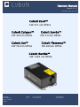
Owners Manual Model 05-01 February 2015 rev 1.22 Cobolt Zouk™ CW 355 nm DPSSL Cobolt Calypso™ Cobolt Samba™ CW 491nm DPSSL CW 532nm DPSSL Cobolt Jive™ Cobolt Flamenco™ CW 561nm DPSSL CW 660nm DPSSL Cobolt Rumba™ CW 1064 nm DPSSL Cobolt AB Phone: +46 8 54591230 [email protected] Vretenvägen 13 Fax: +46 8 54591231 www.cobolt.se SE-171 54 Solna Sweden 2 1. General ........................................................................................................................................................... 3 2. Safety and precaution instructions .................................................................................................................. 3 2.1. Warning labels ........................................................................................................................................ 4 3. Laser design.................................................................................................................................................... 5 4. Laser system description ................................................................................................................................. 5 4.1. Laser Head .............................................................................................................................................. 5 4.2. Controller ............................................................................................................................................... 6 4.3. Cable ...................................................................................................................................................... 7 4.4. Power supply requirements ..................................................................................................................... 7 4.5. Identification labels ................................................................................................................................. 7 5. Operation instructions .................................................................................................................................... 8 5.1. Installation startup operation .................................................................................................................. 8 5.2. Closedown operation .............................................................................................................................. 8 6. Specifications .................................................................................................................................................. 9 6.1. Optical .................................................................................................................................................... 9 6.2. Operational and environmental requirements........................................................................................ 10 6.3. Electrical interfaces ............................................................................................................................... 10 6.4. Mechanical ............................................................................................................................................ 10 7. Mechanical outlines....................................................................................................................................... 11 8. Connector drawings & pin assignment .......................................................................................................... 13 8.1. Analog connector & interlock connector ................................................................................................ 13 8.2. Power connector ................................................................................................................................... 13 8.3. Data connector...................................................................................................................................... 13 9. Operation via data port ................................................................................................................................. 14 9.1. Baud rates and serial port settings ........................................................................................................ 14 9.2. Handshaking ......................................................................................................................................... 14 9.3. RS232 configured controllers ................................................................................................................ 14 9.4. USB configured controllers .................................................................................................................... 14 9.5. Control commands................................................................................................................................ 18 9.6. Direct control ........................................................................................................................................ 19 10. Thermal management................................................................................................................................ 20 11. Cobolt Monitor software ............................................................................................................................ 20 11.1. Installation........................................................................................................................................ 20 11.2. Software instructions ........................................................................................................................ 21 12. Troubleshooting ........................................................................................................................................ 24 13. Warranty and maintenance ........................................................................................................................ 24 14. Declaration of conformity (CDRH model only) ............................................................................................ 25 15. Disclaimers................................................................................................................................................ 25 16. Service....................................................................................................................................................... 25 3 Cobolt ZoukTM CalypsoTM SambaTM JiveTM FlamencoTM RumbaTM 1. General Cobolt lasers are all continuous-wave diode-pumped solid-state (DPSS) laser devices operating at fixed wavelengths as defined in the specifications in Section 6. The lasers have a compact hermetically sealed package and emit a high quality beam with stable characteristics over a wide range of operating conditions. The lasers are designed and manufactured to ensure a high level of reliability. The Cobolt lasers are intended for stand-alone use in laboratory environment or for integration into instrumentation equipment used e.g. in flow cytometry, fluorescence microscopy, particle & flow analysis, DNA sequencing, interferometry, Raman spectroscopy, optical tweezers and laser pumping. 2. Safety and precaution instructions Eye and skin exposure to direct or reflected laser light is hazardous and may be extremely harmful. Always wear eye protection appropriate to the beam wavelength and intensity. The device must be handled by personnel with experience in laser operation, in a laboratory environment and with access to adequate laser safety equipment. Product Output Power (mW) CDRH Class IEC Class 10 and 20 IIIB 3B 200 IIIB 3B 500, 1000, 1500 IV 4 Cobolt Jive™ 561 nm 200 and 300 IIIB 3B Cobolt Jive™ 561 nm 500 IV 4 Cobolt Flamenco™ 660 nm 100 and 300 IIIB 3B Cobolt Flamenco™ 660 nm 500 IV 4 500, 1000, 2000, 3000 IV 4 Cobolt Zouk™ 355 nm Cobolt Calypso ™ 491 nm Cobolt Samba™ 532 nm Cobolt Rumba™ 1064 nm The table below described the maximum irradiance in W/cm2 and appropriate level of eye protection in terms of optical density (OD) for each product line. Product Output Power (mW) Max Irradiance (W/cm2) Eye protection Requirement 20 6.5 > OD 4 200 65 > OD 3 1500 470 > OD 4 Cobolt Jive™ 561 nm 500 160 > OD 4 Cobolt Flamenco™ 660 nm 500 160 > OD 4 3000 460 > OD 4 Cobolt Zouk™ 355 nm Cobolt Calypso ™ 491 nm Cobolt Samba™ 532 nm Cobolt Rumba™ 1064 nm 4 Cobolt ZoukTM CalypsoTM SambaTM JiveTM FlamencoTM RumbaTM Always install the laser system to a properly grounded power outlet; Cobolt lasers contain a laser diode which is sensitive to electrostatic discharge (ESD). CAUTION – use of controls or adjustments or performance of procedures other than those specified herein may result in hazardous radiation exposure. 2.1. Warning labels The Laser Head clearly displays a warning label that shows the location of the laser beam from the aperture and an explanatory label stating the laser safety class compliance of the product. These labels must be visible unless the laser beam is totally enclosed. Visible Class 4 lasers UV Class 3b lasers IR Class 4 lasers Visible Class 3b lasers Examples Hazard Symbol and Aperture Label 5 Cobolt ZoukTM CalypsoTM SambaTM JiveTM FlamencoTM RumbaTM 3. Laser design The radiation from Cobolt lasers is generated by intra-cavity frequency conversion in periodically poled material. The laser beam is expanded in a telescope and emitted through a manual shutter. The residual IR radiation from the pump and the DPSS laser is contained within the laser housing by filtering optics. The laser assembly is equipped with elements for temperature control of the cavity and pump diode. The laser is also featured with an optical feed-back loop which ensures long-term power stability of the emitted visual beam. Control signals and drive currents are supplied via an electrical interface. 4. Laser system description The Cobolt 05-01 laser system consists of four main parts: Laser Head, Controller, Cable and Power supply. The Cobolt Cable should always be used to connect the Laser Head with the Controller. Cobolt Laser Head, Controller and Cable 4.1. Laser Head The Laser Head contains pump diode, laser cavity, beam formatting optics and Peltier elements. The Laser Head gets electrical power and control signals from the Controller via a 26-pin cable. The laser system is CDRH compliant together with the CDRH model of the Controller and the Power supply unit. The Laser Head has a manual shutter as well as a laser hazard label and a laser classification label. 6 Cobolt ZoukTM CalypsoTM SambaTM JiveTM FlamencoTM RumbaTM 4.2. Controller The Controller supplies driving current and control signals to the Laser Head. The operation setpoints are specific to each Laser Head and have been fixed during manufacturing. The status of the laser operation is given via LED indicators: POW (green light) Power is supplied. Blinking LED indicates that the internal temperatures are stabilizing. ON (orange light) Laser light is on in constant current mode. LOCK (orange light) Laser light is on and the output power has been locked to setpoint. The laser is operating according to specifications ERR (red light) An error has occurred. No laser light. The Controller can be configured in two ways (decided at laser purchase): CDRH Controller: A key is supplied to be used to turn on the laser. The laser will be running according to specifications in <3 min. See Section 5.1 for more information. The status of operation is monitored via LED signals. Setting the turn key to its OFF-position puts the laser in stand-by mode. OEM Controller: The Controller is factory set so that no key is needed to turn the laser on. Connecting 15 VDC power supply to the Controller initiates an automatic start-up sequence. See Section 5.1 for more information. The laser will be running according to specifications in <3 min. The operation of the laser can be controlled and monitored via the Data port (supports control commands and analog signals). See Section 9 for further details. When power is supplied to the Controller, regardless of on/off state, the temperature control elements are operating to reach setpoint values. The Controller includes a remote interlock connector, 2-pins on the left hand side within the 6pin analog connector. The connector can be short-circuited with an interlock jumper (included at delivery) for operation of the laser. To make use of the remote interlock as a safety switch, remove the jumper and connect to an external switch. NOTE: when the interlock circuit has been opened during operation, the laser needs to be disconnected from and then reconnected to the power supply in order to start again. Alternatively, it can be re-started using a special sequence of control commands, see Section 9 for further details. 7 Cobolt ZoukTM CalypsoTM SambaTM JiveTM FlamencoTM RumbaTM 4.3. Cable The Cable connects the Laser Head to the Controller. The standard Cable length is 1 m and minimum bending radius 8 cm. When connected care should be taken not to bend or break any of the 26 pins. 4.4. Power supply requirements An appropriate Power Supply Unit (PSU) is supplied by Cobolt with the laser for low volume orders and is plugged into a standard power outlet. The output from the Cobolt supplied PSU is 15 VDC, and the current is 4.2 A (max 63 W). The power supply accepts 90 – 264 VAC and 47-63 Hz. Ripple and noise 1% peak-peak max, 20 MHz bandwidth. Accepted voltage range for the Controller is 11 V - 28 VDC. Specification values are given at 15 VDC. 4.5. Identification labels The Laser Head and Controller are provided with a manufacturer’s identification label including a serial number which is unique for each laser system and a certification label. Manufacturer’s identification labels: CDRH (L) or OEM (R) Model number description: XXXX – 05 – 01 – XXXX – XXX Wavelength Version Power 500 = CDRH controller RS-232 600 = OEM controller RS-232 700 = CDRH controller USB 800 = OEM controller USB xxx = OEM customisation Placement of labels: Hazard Symbol and Aperture Label Manufacturers Certification label 8 Cobolt ZoukTM CalypsoTM SambaTM JiveTM FlamencoTM RumbaTM 5. Operation instructions As standard, all lasers are delivered with the Controller set in Auto-start mode. As soon as power is supplied to the Controller the temperature control elements are operating to reach set-point values and the laser emission will start, unless the keyswitch is enabled (CDRH model). 5.1. Installation startup operation 1. Mount the Laser Head on a suitable heat sink (see Section 10). 2. Ensure that the interlock jumper is connected. 3. Connect the Laser Head to the Controller with the Cable and fasten screws at both ends. 4. Apply 15 VDC to power supply connector on Controller. 5. The laser now goes through the following autostart sequence: Temperature stabilisation (1-2 min). Status LEDs: POW flashing, then POW goes on. (For CDRH model: Turn key switch to start the laser. Status LEDs: ON goes on.) The laser starts (light is emitted) in constant current mode (pre-set time of 60 sec). Status LEDs: ON goes on. The laser locks to pre-set output power (<2 min) and operates according to specifications. Status LEDs: LOCK goes on. 6. Switching the laser ON/OFF (to/from stand-by mode) via control commands or Direct Control is described under sections 9.5 and 9.6. 5.2. Closedown operation 1. Disconnect PSU from mains outlet (turn the key switch to OFF first for CDRH model). 2. Disconnect Controller from PSU. 3. Disconnect Laser Head from Controller (only required for shipping). 9 Cobolt ZoukTM CalypsoTM SambaTM JiveTM FlamencoTM RumbaTM 6. Specifications 6.1. Optical Centre wavelength1 Output power2 Beam divergence Beam diameter (full angle, 1/e2) at aperture Zouk™ 354.8 ± 0.3 nm 10 or 20 mW <0.8 mrad 700 ± 50 µm Calypso™ 491.5 ± 0.3 nm 200 mW <1.2 mrad 700 ± 50 µm Samba™ 532.1 ± 0.3 nm 0.5, 1.0 or 1.5 W <1.2 mrad 700 ± 50 µm Jive™ 561.2 ± 0.3 nm 200, 300 or 500 mW <1.2 mrad 700 ± 50 µm Flamenco™ 659.6 ± 0.3 nm 100, 300 or 500 mW <1.5 mrad 700 ± 50 µm 1064.2 ± 0.6 nm 0.5, 1.0, 2.0 or 3.0 W <1.6 mrad 1000 ± 50 µm Rumba™ Noise 20 Hz – 20 MHz (peak-peak) Noise 20 Hz – 20 MHz (rms) ZoukTM CalypsoTM <2% <5% <1% <0.2% <0.5% <0.1% Long-term power stability (8 hours) SambaTM JiveTM TEM00, M2 <1.1 Spectral linewidth <1 MHz (<0.001 pm) Coherence length >100 m >0.90 : 1 >0.95 : 1 Beam waist location (from exit window) 20 cm Beam angle accuracy <5 mrad Beam position accuracy Beam pointing stability (over 10-40ºC) RumbaTM <2% (±3 ºC) Spatial mode Beam symmetry at aperture FlamencoTM <0.25 mm <10 µrad/ºC, (typical <5 µrad/ºC) Polarization ratio (linear, vertical) >100:1 Residual IR emission <1 mW 1. The wavelength is fixed with this accuracy, while drift is <0.02nm. The wavelength is specified in air. 2. The output power can be adjusted using control commands, see Section 9. Specifications are guaranteed at 100% of nominal power. Recommended power range is 50-100%. Nominal power accuracy 5%. 10 Cobolt ZoukTM CalypsoTM SambaTM JiveTM FlamencoTM RumbaTM 6.2. Operational and environmental requirements Power supply 15 VDC, 4. 2 A. (11-28 VDC accepted) Power consumption, total system (Laser Head + Controller) <63 W (typical ~30 W) Maximum heat dissipation of Laser Head <50 W (typical ~20 W) Maximum Laser Head baseplate temperature 50ºC Warm-up time, from OFF <3 min Ambient temperature, operation 10-40ºC Ambient temperature, storage -10 -> +60ºC Humidity 0-60% RH non-condensing Ambient Air pressure 950-1050 mbar Heat sink thermal resistance, Laser Head <0.2 K/W 6.3. Electrical interfaces Interfaces Connector Function Input power Kycon KPJX-45, 4-pin Power supply to Controller Laser Head to Controller HD-sub 26-pin, male Connection to Laser Head Controller to Laser Head HD-sub 26-pin, female Connection to Controller Data port USB-type mini B Control and monitoring via control commands Remote interlock & Molex 90130-3206 Analog input 5 – 12 V => laser on Analog signals 6.4. Analog input <2.7 V => laser off Mechanical Dimensions: Laser Head 125x70x45 mm (5x2.8x1.8 inches) Controller 190x72x28 mm (7.6x2.9x1.1 inches) PSU dimensions 115x50x35 mm (4.6x2x1.4 inches) Fixation holes, Laser Head size M6 (fitting M4), spacing 115x55 mm Fixation holes, Controller spacing 51x178 mm Cable (Laser Head – Controller) 1 m length, >8 cm bending radius Laser head weight 0.6 kg The information presented here is believed to be accurate and is subject to change without notice. The specifications contained herein cannot be guaranteed outside of normal operational conditions. 11 Cobolt ZoukTM CalypsoTM SambaTM JiveTM FlamencoTM RumbaTM 7. Mechanical outlines Laser Head mechanical outline model 05-01 (dimensions in mm and inches). 12 Cobolt ZoukTM CalypsoTM SambaTM JiveTM FlamencoTM RumbaTM Analog & interlock connector Power connector Data connector OEM & CDRH Controller mechanical outline (dimensions in inches and mm). 13 Cobolt ZoukTM CalypsoTM SambaTM JiveTM FlamencoTM RumbaTM 8. Connector drawings & pin assignment 8.1. Analog connector & interlock connector Manufacturer Molex 90130-3206, mates with 90143-0006. Pin Function 1. Interlock (connect to pin 2 for enable) 2. GND 3. Analog on/off (Direct input) 4. TST (Internal Cobolt use only) 5. LED “Laser on” (5V) 6. LED “Error” (5V) Warning: shortening pin 2 and 4, when the controller is powered up, will erase the controller memory. 8.2. Power connector Kycon KPJX-4S, mates with Kycon KPPX-4P. Grounded shield. Pin Function 1. 0V 2. +11-28 VDC 3. 0V 4. +11-28 VDC 8.3. Data connector Connector USB-type, manufacturer Hsuan Mao C8320-05BFDSB0, mates with connector mini-B. Pin Function 1. +5 V (in series with internal 10 Ohm resistor) 2. RS-232_TX 3. RS-232_RX 4. Not connected 5. 0 V (GND) 14 Cobolt ZoukTM CalypsoTM SambaTM JiveTM FlamencoTM RumbaTM 9. Operation via data port 9.1. Baud rates and serial port settings To communicate with the laser, a communication cable needs to be ordered separately. Each Controller is shipped from the factory with a fixed baud rate (115200), which cannot be changed in the field. The other serial port parameters are: 8 data bits, 1 stop bit and no parity. Hardware flow control is not supported. Each command to the Controller must be terminated by a carriage return. All commands are case-sensitive. Leading and trailing white space is ignored, but command arguments must be delimited by a single space character (ASCII 32). 9.2. Handshaking Under no circumstances does the Controller initiate communication; it only transmits characters in response to a message. Every message to the Controller generates a response, either a numerical value or the acknowledgment string “OK”. In the event that the Controller receives a message that it cannot interpret, it responds: “Syntax error:” followed by the complete command string (minus the termination character) that caused the error. Every Controller response is terminated by a carriage return (ASCII 13) and a full stop is used with floating numbers. 9.3. RS232 configured controllers To communicate with the laser, a communication cable is supplied. Each Controller is shipped from the factory with a fixed baud rate (115200). The other serial port parameters are: 8 data bits, 1 stop bit and no parity. Hardware flow control is not supported. Each command to the Controller must be terminated by a carriage return. All commands are case-sensitive. Leading and trailing white space is ignored, but command arguments must be delimited by a single space character (ASCII 32). 9.4. USB configured controllers The USB configured controllers requires a driver for communication with a computer. The USB driver must be installed and can be downloaded from the Cobolt website (www.cobolt.se). When installed, a virtual COM port will be created to communicate with the Controller. To install the USB driver in Windows 7 follow these instructions: 1. Go to the Control Panel and choose Hardware and Sound. 15 Cobolt ZoukTM CalypsoTM SambaTM JiveTM FlamencoTM RumbaTM 2. Under the Devices and Printers section, choose Device Manager. 3. Under Other devices, find the device called Cobolt Laser Driver MLD/DPL. Right-click it and chose Update Driver Software. 4. On the next screen chose the Browse my computer for driver software option. 16 Cobolt ZoukTM CalypsoTM SambaTM JiveTM FlamencoTM RumbaTM 17 Cobolt ZoukTM CalypsoTM SambaTM JiveTM FlamencoTM RumbaTM 5. Click browse, and find folder on your computer where the USB driver is stored. 6. Windows security may warn you that the publisher of the driver is unverified. Choose Install this driver software anyway. 7. The installation should now be complete. 18 Cobolt ZoukTM CalypsoTM SambaTM JiveTM FlamencoTM RumbaTM 9.5. Control commands The laser is delivered with the Controller set in autostart mode (see Section 5.1 for autostart sequence description). For system integration the autostart sequence can be disabled (some commands require autostart disabled). The controller is factory set for RS-232 communication (-500/-600 model number) or USB communication (-700/800 model number). As long as power is supplied to the Controller the temperature control elements are always operating to reach set-point values and the laser will be idle waiting for the next command. All arguments are in lower case and separated by a space (ASCII 32). Command Function Argument Returned value hrs? Get laser head operating hours Float ilk? Get interlock state 0 = OK, 1 = interlock open Enable/disable autostart @cobas With autostart disabled the laser will not go through the standard warm-up sequence, see 0 = disable, 1 = enable Section 5.1. @cobas? Get autostart enable state 0 = disabled, 1 = enabled l? Get laser ON/OFF state 0 = OFF, 1 = ON Laser ON l1 Requires autostart disabled. Use this command for manual ON (OEM models). Laser OFF l0 Use this command for manual OFF (OEM models). p? Get set output power Float (W) p Set output power pa? Read output power Float (W) i? Get drive current Float (A) slc Set drive current Float (W) (e.g. p 0.050 for 50 mW) Float (A) Int [0:15] Bit 0 = “POWER ON” Bit 1 = “LASER ON” leds? Status of 4 LEDs Bit 2 = “LASER LOCK” Bit 3 = “ERROR” 1 = LED on 0 = LED off 0 = no fault f? 1 = temperature error Get operating fault 3 = open interlock 4 = constant power fault cf Clear fault @cobasdr Enable/disable direct control 0 = disable, 1 = enable 19 Cobolt ZoukTM CalypsoTM SambaTM JiveTM FlamencoTM RumbaTM See sect 9.4 for description @cobasdr? Get direct control enable state 0 = disabled 1 = enabled sn? 32-bit unsigned integer Get serial number Laser ON after interlock Forces the laser into @cob1 autostart without checking if autostart is enabled (OEM models). @cobasky? Get key switch state 0 = disabled, 1 = enabled Enable/disable key switch With the key @cobasky switch disabled the laser is not CDRH compliant 0 = disable, 1 = enable and laser safety no longer applies. For re-starting the laser with control commands after having opened the remote interlock switch, execute “cf” for clear fault followed by “@cob1” to restart the laser. On CDRH models the key switch is the only way to re-start. The output power can be adjusted from 10-110% of nominal power using the “p” command. Specifications are guaranteed at 100% of nominal power. Recommended power range is 50-100%. 9.6. Direct control The Direct Control feature enables turning the laser ON/OFF using a 5-12 VDC signal. After having configured the Controller for Direct Control operation (factory set or by executing @cobasdr 1), the laser can only start-up when 512V VDC (max 12.5 VDC) is applied to pin 3 on the analog connector with 0 VDC on pin 2 as reference. Shifting the signal to 0 VDC on pin 3 will turn the laser off and put the laser in stand-by mode (status LED:s is POW and not flashing). This input only controls the on/off state of the laser and cannot be used to modulate the power output. 20 Cobolt ZoukTM CalypsoTM SambaTM JiveTM FlamencoTM RumbaTM 10. Thermal management To ensure operation within given specifications and for the warranty to be valid, the Laser Head must be attached to a heat sink providing a thermal resistance of <0.2 K/W. The Cobolt heatsink meet this requirement. This value is the difference between the maximum allowed Laser Head base plate temperature (50ºC) and the maximum specified ambient temperature at the air-heatsink interface (40ºC), divided by the maximum power dissipated from the laser (~50 W for the highest power models at high ambient temperatures). The mounting surface should be flat (within 0.05 mm over mounting surface). It is recommended to use a thermal heat compound between the Laser Head and the heat sink to provide good thermal contact. For assistance in thermal management and system integration, please contact Cobolt’s technical support. Typical curve of heat dissipation with respect to base plate temperature under extreme operating conditions with good thermal contact between the laser head and the temperature controlled base plate 11. Cobolt Monitor software The Cobolt Monitor software provides a graphical way to monitor the laser performance and to change power, operation mode and other settings. The software can connect to the laser either via RS-232 port or via USB, depending on the type of controller. The USB driver must be installed manually and can be downloaded from the Cobolt website (www.cobolt.se). 11.1. Installation The GUI software Cobolt MonitorTM is developed and tested with operative systems Windows XP, Windows Vista, Windows 7 and Windows 8. Microsoft .NET 2.0 is required to run the Cobolt Monitor software. Most computers with operative systems Windows XP, Windows Vista, Windows 7 and Windows 8 has this included as standard. The Cobolt Monitor software is a standalone executable file packaged in a library with other files needed to run the program. No installation of the software is required and the GUI is started by running the executable. The GUI can be 21 Cobolt ZoukTM CalypsoTM SambaTM JiveTM FlamencoTM RumbaTM downloaded from the website www.cobolt.se. The files required are placed in a zipped folder. Extract the folder on the PC. The folder with files can be placed on any storage device like CD, DVD, USB stick or Hard drive, and run from there. Make sure that all the files in the folder are complete. 11.2. Software instructions The software automatically searches for Cobolt devices every 5 seconds and automatically connects the laser if detected. The software can identify USB connected lasers as well as RS232 connected lasers. The first GUI window that appears in the Cobolt Monitor software. Once the laser is connected the laser can be controlled from the box dedicated for the laser. The interface, found in the following figure, is intended for typical user cases. Only the relevant information is presented on this level displaying only the status the laser is in and relevant choices to make. Here follows a short description of how to use the GUI on this level. 22 Cobolt ZoukTM CalypsoTM SambaTM JiveTM FlamencoTM RumbaTM Laser successfully connected. Laser ON – Turns the laser ON. If the laser is in autostart mode this is equivalent to “restart”. Laser OFF – Turns the laser OFF. Mode – Gives a choice of operational modes possible to choose for the laser model. For 05-01 laser models Constant Power or Constant Current operation can be chosen. Only relevant choices are presented to the mode of operation chosen. Commands – opens a command communications window to send commands directly to the laser controller. Message – highlights important information of the laser status to the user. Disconnect – allows to disconnect the GUI in a controlled way. Note! The communication cable should not be pulled out when the GUI is connected. The communication within the controller can malfunction and this might require a power restart of the driver. To disconnect the laser click “Disconnect” or close the GUI completely. It is also possible to disconnect by powering the laser OFF. In this case the GUI will automatically close the GUI windows of the laser. Clear Fault - is displayed in the event of a fault. The user can deal with the cause of the fault and then press “Clear Fault” and then restart the laser by clicking “Laser ON”. Example: if the interlock loop is open the user must make sure the loop is closed again before issuing a “Clear Fault” followed by “Laser On”. 23 Cobolt ZoukTM CalypsoTM SambaTM JiveTM FlamencoTM RumbaTM More – opens an additional GUI window containing more detailed information of the laser status. Cobolt Monitor with a second GUI layer expanded reveling a more detailed monitoring. Here the sections within the “Cobolt Monitor – More” window is described: TEC Settings – shows the running status and the fault status for the laser’s internal thermoelectric coolers (TEC). Depending on model the laser can have up to four TEC’s active. Only the activated model specific TEC’s are displayed. Laser Operation Mode and Settings - displays the set laser power. The user can switch between constant power mode and constant current mode. Likewise, there are boxes to set the constant power level and constant current level. The output power (as monitored measured on an internal photodiode) and the current through the laser pump diode are both displayed. Autostart Program - displays whether the laser is in CDRH or OEM mode and displays the current laser operational status. 5V direct input is set here, see Section 9.6. There are also buttons to “abort” the autostart sequence or to “restart” the laser after a fault. 24 Cobolt ZoukTM CalypsoTM SambaTM JiveTM FlamencoTM RumbaTM Fault Status – displays ERROR messages. In the event of an ERROR the laser action is stopped. When the reason for ERROR event is understood and the problem is addressed the fault status can be cleared with “Clear Fault”. If the Autostart Program is enabled click restart to restart the laser. LED Status - displays the LEDs that are currently illuminated on the Control Box, see Section 4.2. These are displayed even if the laser is in OEM mode. 12. Troubleshooting In the unlikely case of a problem occurring, use the table below to help identify the error. Some faults can be fixed remotely. Call Cobolt support or your representative to identify corrective action. LEDs Status off POW Explanation Action Mains power off Check connections flashing x POW X Temperatures not stabilised Check if heatsink is sufficient LOCK X Laser can not lock in constant power, current limit has been reached Check if heatsink is sufficient. Contact the factory. ERROR On Error in laser parameters If lights at start-up check cable connections, if lights >5s after start-up contact the factory 13. Warranty and maintenance Cobolt provides a system warranty of 24 months after delivery, with unlimited number of operation hours for products Samba, Jive, Flamenco and Rumba. Cobolt provides a system warranty of 12 months after delivery, with unlimited number of operation hours for products Calypso and Zouk. The laser systems are designed for modular replacement or repair in the event that the Laser Head or Controller malfunctions. Warranty is invalid if the laser system is operated outside of the specific limits and conditions as outlined in this document. The Cobolt lasers are contained in sealed enclosures and should not be opened for any reason. The warranty will be voided if any of the system units are opened. All laser parameters are set at the factory, and there are no adjustments required. Maintenance is limited to wiping dirt off the enclosures and cleaning the aperture. Clean the aperture with a standard photographers’ lens airbrush. 25 Cobolt ZoukTM CalypsoTM SambaTM JiveTM FlamencoTM RumbaTM 14. Declaration of conformity (CDRH model only) The Cobolt 05 lasers are designed and manufactured to comply with EC Low Voltage Directive and EC EMC Directive in their standard configuration of Laser Head, Controller, standard 1m cable and supplied with a Cobolt power supply unit. The equipment might not conform to the CE directive if any part of the supplied equipment is replaced with a part not supplied by Cobolt. The following harmonized standards are in use: Electrical safety: IEC 61010-1:(2010), UL 61010-1, CAN/CSA-C22.2 No. 61010-1 Laser Class: IEC-60825-1, CFR 1040.10-2002 and 1040.11-2002 EMC: EN 61326-1:2006, incl EN 55011 Class A and FCC Part 15 subpart B class B In addition, Cobolt laser products pass ETC 900 019-2-2 Transport and Vibration Standards including IEC 600682-64, IEC 60068-2-29, IEC 60068-2-32, and Shock and Vibration IEC 60068-2-29. Cobolt lasers are RoHS2 compliant as defined by the EC Directive 2011/65/EU. Disabling the key-switch nullifies the CE marking as this violates the laser safety standard. 15. Disclaimers Cobolt will assume no responsibility for damage incurred by faulty customer equipment, such as measurement equipment, cables etc, used in conjunction with Cobolt lasers. Cobolt makes no warranty of any kind with regard to the information contained in this guide, included but not limited to, implied warranties of merchantability and suitability for a particular purpose. Cobolt shall not be liable for errors contained herein nor for incidental or consequential damages from the furnishing of this information. No part in this manual may be copied, reproduced, recorded, transmitted, or translated without the express written permission by Cobolt. 16. Service If the laser does not function, do not attempt to open any of the units, or the warranty will be voided. Call or e-mail your local Cobolt representative for consultancy and to request an RMA number (see back cover for contact information). If an RMA number us issued and the laser needs to be shipped back to Cobolt or your local representative, please pack the complete system for shipment using the original package or equivalent. Ensure the unit is free from thermal paste before packing. The warranty covers repair or replacing the unit at the option of Cobolt. Contact Information Cobolt headquarters Cobolt AB Phone: +46 8 545 91 230 Vretenvägen 13 Fax: +46 8 545 91 231 SE-171 54 Solna E-mail: [email protected] Sweden Web: www.cobolt.se Sales representatives Australia Benelux Brazil Warsash Scientific Pty Ltd Laser 2000 Benelux CV Photonics Instrumentos Phone: +61 2 9319 0122 Phone: +31 297 266 191 Phone: +55 11 2910 6852 Fax: +61 2 9318 2192 Fax: +31 297 266 134 Fax: +55 11 2910 6852 www.warsash.com.au www.laser2000.nl www.photonics.com.br China Estonia, Latvia, Lithuania France DynaSense Photonics Co. Ltd. Optek Ltd. Optoprim Phone: +86 (0)10 83503853 Phone: +37 129 781 582 Phone: +33 1 4190 6180 Fax: +86 (0) 10 83503622 Fax: n/a Fax: +33 1 4190 6189 www.dyna-sense.com www.optek.lv www.optoprim.com Germany, Austria, Switzerland India India Von Gegerfelt Photonics New Age Instruments and Materials Dynotech Instruments Pvt. Ltd Phone: +49 6251 860 99 20 Phone: +91 124 4086513 16 Phone: +91 124 4086513 16 Fax: +49 6251 860 99 17 Fax: +91 124 2331653 Fax: +91 124 2331653 www.vgphotonics.eu www.newagein.com www.dynotech.in Israel Italy Japan Lahat Technologies Ltd. Optoprim S.r.l. Kantum Electronics Co Ltd Phone: +972 4 999 0151 Phone: +39 39 834 977 Phone: +81 3 37581113 Fax: +972 9 76 46 204 Fax: +39 39 284 5269 Fax: +81 3 37588066 www.lahat.co.il www.optoprim.it www.kantum.co.jp Japan Poland Russia & Belarus Pneum Co, Ltd Japan Amecam Azimuth Photonics Phone: +81 48 985 2720 Phone: +48 (22) 207 22 78 Phone: +7 495 792 39 88 Fax: +81 48 985 27 21 Fax: +48 (22) 207 22 77 Fax: +7 495 958 23 09 www.pneum.co.jp www.amecam.pl www.azimp.ru Singapore, Malaysia, Thailand South Korea Spain & Portugal Photonitech(Asia) Pte Ltd SM Tech Laser Technology SI Phone: +65 6749 9031 Phone: +82 42 8244413 Phone: +34 93 750 0121 Fax: +65 6233 9171 Fax: +82 42 8244414 Fax: +34 93 750 0323 www.photonitech.com www.lasersystem.co.kr www.laser-technology.com Taiwan UK & Ireland USA, Canada & Mexico Tayhwa Technology Co. Ltd Laser Lines Ltd Cobolt Inc Phone: +886 2 23569737 Phone: +44 1295 672 500 Phone: +1 (408) 708 4351 Fax: +886 2 23569659 Fax: +44 1295 672 550 Fax: +1 (408) 490 2774 www.tayhwa.com.tw www.laserlines.co.uk www.coboltinc.com