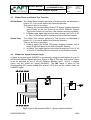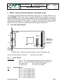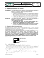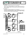
1
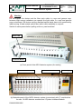
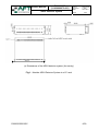
Owners Manual P000032553 (9-1030000079-001) ARC4 Detector System Author: Approved: Date: Page: Neha Gupta C. Weil 08.07.2011 1/30 Owners Manual ARC4 Detector System P000032553.DOC 1/30 Owners Manual P000032553 (9-1030000079-001) ARC4 Detector System Author: Approved: Date: Page: Neha Gupta C. Weil 08.07.2011 2/30 Contents 1 Introduction......................................................................................................... 4 2 Scope of supply.................................................................................................. 7 3 ARC4 - Arc Detector Module.............................................................................. 8 3.1 Input and Output Signals................................................................................ 8 3.1.1 Input Signal ............................................................................................. 8 3.1.2 Output Signals......................................................................................... 8 3.1.3 Remote Control ....................................................................................... 9 3.1.4 Signal Selection..................................................................................... 10 3.1.5 Reset and Test Function ....................................................................... 10 3.1.6 Power Control Function ......................................................................... 11 3.2 Detector Delay Time .................................................................................... 11 3.3 Test Points (optional use) ............................................................................ 11 3.4 Product Specifications.................................................................................. 12 4 ARC4 – System Interface Module - Standard ................................................. 13 4.1 Input and Output Signals.............................................................................. 13 4.1.1 Input Signals.......................................................................................... 13 4.1.2 Output Signals....................................................................................... 13 4.2 Signal Selection ........................................................................................... 14 4.2.1 Input Signal Selection............................................................................ 14 4.2.2 Output Signal type Selection ................................................................. 14 4.3 Global Reset and Global Test Function ....................................................... 15 4.4 Global Arc Signal Standard Logic ................................................................ 15 5 ARC4 – System Interface Module - Selectable Logic .................................... 16 5.1 Input and Output Signals.............................................................................. 16 5.1.1 Input Signals.......................................................................................... 16 5.1.2 Output Signals....................................................................................... 16 5.2 Signal Selection ........................................................................................... 17 5.2.1 Input Signal Selection............................................................................ 17 5.2.2 Output Signal type Selection ................................................................. 17 5.3 Global Reset and Global Test Function ....................................................... 18 5.4 Global Arc Signal Selectable Logic .............................................................. 18 5.4.1 Logic A (default) .................................................................................... 18 5.4.2 Logic B .................................................................................................. 18 5.4.3 Logic C .................................................................................................. 19 5.4.4 Logic D .................................................................................................. 19 6 ARC4 – Optical Test Board .............................................................................. 22 6.1 Input and Output Signals.............................................................................. 22 6.1.1 Input Signal ........................................................................................... 22 6.1.2 Output Signals....................................................................................... 23 6.2 Product Specifications.................................................................................. 23 P000032553.DOC 2/30 Owners Manual P000032553 (9-1030000079-001) ARC4 Detector System Author: Approved: Date: Page: Neha Gupta C. Weil 08.07.2011 3/30 7 Power Supply Specification............................................................................. 24 8 Fibre Optic Cables............................................................................................ 25 8.1 8.2 9 Multimode Glass Fibre Cable....................................................................... 25 Plastic Fibre Cable ....................................................................................... 26 ARC - Viewports ............................................................................................... 27 9.1 9.2 9.3 Pressurized Arc Viewport............................................................................. 28 Non-Pressurized Arc Viewport ..................................................................... 29 Non-Pressurized Arc Viewport with Optical Test Port .................................. 30 P000032553.DOC 3/30 Owners Manual P000032553 (9-1030000079-001) ARC4 Detector System Author: Approved: Date: Page: Neha Gupta C. Weil 08.07.2011 4/30 1 Introduction Microwave devices and systems working in high-power area may quickly build up extremely high electric field strength. If the disruptive strength of the air or the gas filled in the device exceeds, because of humidity or contamination settles in the device, electrical breakdown in the form of arcing is possible. In this case part of the microwave energy is reflected and the arc travels back to the source. If the arc energy reaches values above 5 J, waveguide and microwave source might be subject to considerable damages and might even be completely destroyed. Up to an energy level of about 1 J the energy dissipation induced by an arc leads to an evaporation of particles contaminating the waveguide, only. AFT high-sensitive arc-detectors detect the light emitted by an arc within microseconds and even with small light quantities the very first indication of an arc emergence. Their output signal emerges after about 1 J of energy has been dissipated and it can be used as interlock signal starts switching-off of the microwave generator in time. Due to our efficient detectors permanent damages to the system can be avoided. The ARC4 detector system is a modular expansible system in a 19" rack, shown in Fig. 1. The basic set-up consists of a 19” housing, which includes a power supply available for 115VAC or 230VAC and a bus system for up to 17 modules. The system can be equipped with up to 16 ARC4 Arc Detector Modules, and optional components such as one ARC4 System Interface Module and ARC4 Optical Test Board. A low-loss multimode glass fiber cable transfers the light of an arc from a viewport on the microwave device to the optical input of the ARC4 Detector Module. The connector type used on both sides is FSMA ¼” UNS-2A thread. For a description about the AFT Multimode Glass Fiber Cable and AFT ARC - Viewports refer to section 8 and 9, respectively. The basic function of an Arc Detector Module is to detect the light produced by an arc by using a high-sensitivity photodiode and to give out the Arc out signal. For the description about input and output signals refer to section 3. To test precisely the functionality of the Arc Detector Module along with the Multimode Glass Fiber Cable AFT offers an optional Optical Test Board, described in section 6. Each arc detector has only one optical input, so one arc detector is capable to detect an arc occurring at one view port. For bigger apparatus more number of arc detectors might be required in connection with a module, which is capable to logically combine the signals of various arc detectors and generates a global arc output signal (GLBARC). This requirement is fulfilled by AFT´s ARC4 System Interface Module, available in two different configurations: (1) The standard ARC4 System Interface Module that allows a logical ORcombination of up to 16 Arc Detector Module signals, described in section 4. (2) The ARC4 System Interface Module with Selectable Logic, that allows the user to choose between 4 different logical combinations of maximum up to 4 Arc Detector Module signals, described in section 5. P000032553.DOC 4/30 Owners Manual P000032553 (9-1030000079-001) ARC4 Detector System Author: Approved: Date: Page: Neha Gupta C. Weil 08.07.2011 5/30 Warning Do not expose the device and the fiber optic cable to x-rays and gamma rays, because high energy radiations can opaque the light cable. In x-rays and gamma rays environment, the device and the standard optical cable have to be protected by lead housing. A lead-coated optical fiber cable is also available on request. Switch of mains power before pulling out/in any card modules ! Status LED Test/Reset Button (a) Front panel of the ARC4 detector system (Arc sentry) ARC Detector Modules System Interface Module Power Supply (b) Backside panel of the ARC4 detector system (connectors) with 17 module slots for max. 16 ARC detector modules and 1 System Interface Module. P000032553.DOC 5/30 Owners Manual P000032553 (9-1030000079-001) ARC4 Detector System Author: Approved: Date: Page: Neha Gupta C. Weil 08.07.2011 6/30 484,00 (c) Dimensions of the ARC4 detector system (Arc sentry) Fig.1 : Modular ARC4 Detector System in a 19” rack P000032553.DOC 6/30 Owners Manual P000032553 (9-1030000079-001) ARC4 Detector System Author: Approved: Date: Neha Gupta C. Weil 08.07.2011 Page: 7/30 2 Scope of supply Depending on the customized configuration, the ARC4 Detector system is supplied with the following components: Product name ARC4 – 19” housing 19” (empty), 115V or 230V including: 1 x 19” housing with 17 cards slots, including power supply 1 x Mains connector IEC-60320-C13 for mains cable assembly 1 x Owners Manual ARC4 – Arc Detector Module for 19” each module includes: 1 x ARC4 - Arc detector module card 1 x DB9 male connector for cable assembly 1 x Standard metal hood for DB9 connector 2 x BNC male connector for coaxial cable assembly ARC4 – System Interface Module - Standard (optional) including: 1 x ARC4 - System interface module card 2 x DB15 male connector for cable assembly 2 x Standard metal hood for DB15 connector ARC4 – System Interface Module - Selectable logic (optional) including: 1 x ARC4 - System interface module card 2 x DB15 male connector for cable assembly 2 x Standard metal hood for DB15 connector ARC4 – Optical Test Board (optional) including: 1 x ARC4 - Optical test module card 1 x DB9 male connector for cable assembly 1 x Standard metal hood for DB9 connector P000032553.DOC 7/30 Owners Manual P000032553 (9-1030000079-001) ARC4 Detector System Author: Approved: Date: Page: Neha Gupta C. Weil 08.07.2011 8/30 3 ARC4 - Arc Detector Module The Arc Detector Module detects the light produced by an arc by using a highsensitivity photodiode and gives out the Arc out signal. 3.1 Input and Output Signals 3.1.1 Input Signal Optical input. Receives arc signal through optical fiber cable coming from view port. Connector type: FSMA 1/4”-36 UNS-2A. Light detector: DB9 Remote Control PWR TTL BNC Arc out O.C. light out BNC FSMA Light detector F/P O/C sensivity ARC4.001.00.D01 Fig.2: ARC4 - Arc Detector Module Card ARC4.001.00 3.1.2 Output Signals Light out: Analog output voltage of the light detector Range: 0V to –3.5V, output impedance 1k Connector type: BNC female. Arc out: Digital output signal of the arc detector, which can be chosen between TTL or open collector (O.C.) by setting the jumpers TTL and O.C. on the PCB as follows: (1) O.C. closed & TTL open = (2) TTL closed & O.C. open = O.C. output signal (default) TTL output signal Warning: Do not close both, TTL & O.C. It will damage the device! Connector type: BNC female. P000032553.DOC 8/30 P000032553 (9-1030000079-001) Owners Manual ARC4 Detector System 3.1.3 Author: Approved: Date: Page: Neha Gupta C. Weil 08.07.2011 9/30 Remote Control The remote control interface is designed to control the device by computer. lt has both, digital Arc out signals (TTL and O.C.) and Power fail out signal, which detects the Arc Detector Module power failure condition. For details refer to section 2.1.6. It also has a Reset and a Test input from the computer to delete the previous output and to test the current status of arc, respectively. For detail explanation refer to section 3.1.5. Connector type: DB9 female. Pin: Description: (1) (2) (3) (4) (5) (6-9) Arc out - Open collector output Power fail out - Open collector output Internal ground. +5V internal operating voltages at 4.7 k. Arc out -TTL output. Input signals for remote control of the „Reset“ and „Test“ switches Power Arc out Ground fail out (Earth) open col. open col. Arc out +5V TTL Sign. (4.7k) 4 5 9 + 3 7 8 - "Reset" -relay 5V;10mA;0.5s 1 2 + 6 - "Test" -relay 5V;10mA;0.5s Fig.3: Remote Control DB9 connector P000032553.DOC 9/30 Owners Manual P000032553 (9-1030000079-001) ARC4 Detector System 3.1.4 Author: Approved: Date: Page: Neha Gupta C. Weil 08.07.2011 10/30 Signal Selection The jumpers F/P and O/C on the PCB of the Arc Detector Module (as shown in Fig.2) are responsible for the following selections: The jumper F/P selects an auto reset or manual reset function for the Arc out signals. See section 3.1.5 for details on reset functions. open = Auto reset after about 100µs (default). The Arc out signal stays for about 100µs and comes back to zero in case of no light (arc) at the Light detector input. F/P Jumper : closed = Manual reset is required. The Arc out signal stays until the Reset function is performed by pushing T/R button or sending a reset signal manually. The O/C jumper selects the type of Arc out signals (TTL and O.C.) as follows: O/C Jumper : open = Active high outputs (default). When an arc is detected, the TTL output goes high and the Open collector stops conducting and visa versa, when there is no arc. closed = Active low outputs. When an arc is detected, the TTL output goes low and the Open collector starts conducting and visa versa, when there is no arc. 3.1.5 Reset and Test Function The status of an arc signal is stored in a flip-flop and indicated by a corresponding LED located at the front panel of the ARC4 Detector System (Arc sentry). A green LED status indicates the “zero” value of the flip flop, i.e. no arcing. The red LED status displays the “one” value of the flip flop, i.e. the presence of an arc. To check the functionality of Arc Detector Module and to bring it back to the normal functioning state, the Test and Reset function are used, which are described as follows: Reset: The reset function sets the value of the flip-flop to “zero” in case of no light at the Light detector input of the Arc Detector Module. This can be done in two ways: 1. Auto reset : It is an automatical reset of all arc output signals of the detector module after about 100µs. For a reset of the Arc LED indicator a manual reset needs to be performed. 2. Manual reset : It is a non automatic or a manual way of resetting the system. This can be done in two ways: 2.a. Pushing the corresponding T/R button (which toggles between test and reset) at the front panel of the ARC4 Detector System. 2.b A remote reset signal can be sent through the Pin8/9 of the DB9 connector at the backside panel of the Arc Detector Module. P000032553.DOC 10/30 Owners Manual P000032553 (9-1030000079-001) ARC4 Detector System Test: 3.1.6 Author: Approved: Date: Neha Gupta C. Weil 08.07.2011 Page: 11/30 In the test function a light pulse is sent (using an internal LED) to the Light detector to perform the test of the hardware functionality of an Arc Detector Module. This can be done in two manual ways: 1. Pushing again the corresponding T/R button (which toggles between test and reset) at the front panel of the ARC4 Detector System. 2. A remote test signal can be sent through the Pin6/7 of the DB9 connector at the backside panel of the Arc Detector Module. Power Control Function Power failures occur when the supply voltage (+5V or -5V) in an Arc Detector Module decreases by 0.2 V. It can be detected by the Power fail out signal available at Pin2 of the DB9 connector. The jumper PWR on the PCB of the Arc Detector Module (as shown in Fig.2) is used to send the Power fail out signal as the Arc out signal. PWR jumper: Closed Open 3.2 = Power fail out signal is given out as an Arc out signal.(default) = Power fail out signal is not given out as an Arc out signal. Detector Delay Time The delay time is the time required for sending an arc out signal, when an arc is detected. It depends on the strength of the light signal. Typically, the delay time is between 2s (strong signal) and 7s (weak signal). 3.3 Test Points (optional use) In case of a power failure two test points TP1, TP3 can be checked. These two test points are present on the backside of the PCB. The voltage with reference to ground at these test points (in case of no power failure) should be: TP1: 5 mV to -10 mV (When the light detector has no light signal) TP1: ca. -1.2 V (When the light detector has daylight signal) TP3: -50 ± 5 mV (A constant reference voltage) P000032553.DOC 11/30 Owners Manual P000032553 (9-1030000079-001) ARC4 Detector System 3.4 Author: Approved: Date: Page: Neha Gupta C. Weil 08.07.2011 12/30 Product Specifications Absolute maximum ratings: Storage temperature Operating temperature (full power) -40°C to +85°C 0°C to 40°C Analog output signal “Light out”: Voltage range: At output impedance of: 0V to –3.5V 1k O.C. output signal “Arc out and DB9 (Pin1)”: Open collector current: 50mA Open collector voltage: 50V Open collector resistor: 470 TTL output signal “Arc out and DB9 (Pin5)”: TTL output VOH (IOH: 1mA) 4.67V(HIGH) TTL output VOL (IOL: 1mA) 0.33V(LOW) Relays for remote Test and Reset functions: Voltage 5V Current 10mA Specifications for typical operating conditions at 25°C: Delay time for arc detection Auto reset time Minimum light intensity for detection P000032553.DOC 2 µs to 7 µs 85 µs to 105 µs 2 lux 12/30 Owners Manual P000032553 (9-1030000079-001) ARC4 Detector System Author: Approved: Date: Page: Neha Gupta C. Weil 08.07.2011 13/30 4 ARC4 – System Interface Module - Standard The standard System Interface Module gives out a single Global Arc out signal GLBARC in TTL logic, which is a logical OR-combination of up to 16 Arc Detector Module signals. All Arc Detector Module output signals are separately available as TTL signals. In addition, the interface card has two TTL inputs for remote control of the global reset and the global test function. 4.1 Input and Output Signals F1 X2 DIP switches DB15 ARC1 ARC2 ARC3 ARC4 ARC5 ARC6 ARC7 ARC8 DB15 ARC9 ARC10 ARC11 ARC12 ARC13 ARC14 ARC15 ARC16 X8 INV ARC4.002.00.A02 Fig.4: ARC4 - System Interface Module Card ARC4.002.00 X2 and X8 input/output connectors: Connector type: DB15 female. 4.1.1 Input Signals X2 and X8: Pin 11 = TTL input global reset signal (refer to section 4.3) Pin 12 = TTL input global test signal (refer to section 4.3) TTL input VOH 3.6V< VOH <5V (HIGH) TTL input VOL 0V< VOL <1V (LOW) 4.1.2 X2: Output Signals Pin 1 = arc out signal (arc1) Pin 2 = arc out signal (arc2) Pin 3 = arc out signal (arc3) Pin 4 = arc out signal (arc3) Pin 5 = arc out signal (arc5) Pin 6 = arc out signal (arc6) Pin 7 = arc out signal (arc7) Pin 8 = arc out signal (arc8) P000032553.DOC 13/30 Owners Manual P000032553 (9-1030000079-001) ARC4 Detector System Author: Approved: Date: Page: X8: Pin Pin Pin Pin Pin Pin Pin Pin X2 and X8: Pin 9 = +5V / 10mA max.– fused 250mAF Pin 10 = GLBARC, global arc output signal, see 4.4 Pin 13-15 = ground 4.2 4.2.1 Neha Gupta C. Weil 08.07.2011 14/30 1 = arc out signal (arc9) 2 = arc out signal (arc10) 3 = arc out signal (arc11) 4 = arc out signal (arc12) 5 = arc out signal (arc13) 6 = arc out signal (arc14) 7 = arc out signal (arc15) 8 = arc out signal (arc16) Signal Selection Input Signal Selection The DIP switches ARC1-ARC16 are used to select the arc detector signals that are processed in the system interface module and provided as output signals at X2 and X8. Right switch position Left switch position = signal is selected (default) = signal is not selected. Example for DIP switch positions: ARC1 is selected (default) ARC2 is selected (default) ARC3 is not selected . . . 4.2.2 Output Signal type Selection The jumper INV on the PCB of the System Interface Module as shown in Fig.4 is responsible for the type of all output signals described as follows: INV Jumper : P000032553.DOC closed (INV=1) = all output signals are active low (default). open (INV=0) = all output signals are active high. 14/30 Owners Manual P000032553 (9-1030000079-001) ARC4 Detector System 4.3 Author: Approved: Date: Page: Neha Gupta C. Weil 08.07.2011 15/30 Global Reset and Global Test Function Global Reset: The Global Reset function performs a Reset function, as described in section 3.1.5, but on all applied Arc Detector Modules. This can be done in two ways: 1. Pushing the corresponding Global T/R button (toggling between test & reset) at the front panel of the ARC4 Detector System. This button works only and only if an interface module is present. 2. A Global reset signal can be sent either through the Pin11 of X2 or Pin11 of X8 at the DB15 connectors of the interface module. Global Test: 4.4 The Global Test function performs a Test function, as described in section 3.1.5, but on all applied Arc Detector Modules. This can be done in two ways: 1. Pushing again the Global T/R button (toggling between test & reset) at the front panel of the ARC4 Detector System. 2. A Global Test signal can be sent either through the Pin12 of X2 or Pin12 of X8 at the DB15 connectors of the interface module. Global Arc Signal Standard Logic A global arc output signal GLBARC is generated by a logical combination of up to 16 Arc Detector Module signals as inputs, shown in Fig. 5. This logic implies that if there is an arc detected by any of the Arc Detector Modules (arc1….arc16), it triggers (gives out) the global arc signal (GLBARC). The INV signal is given by the corresponding INV jumper setting (see section 4.2.2) and can be used to invert the GLBARC signal. Fig.5: Logic of the standard ARC4 - System Interface Module P000032553.DOC 15/30 Owners Manual P000032553 (9-1030000079-001) ARC4 Detector System Author: Approved: Date: Neha Gupta C. Weil 08.07.2011 Page: 16/30 5 ARC4 – System Interface Module - Selectable Logic The System Interface Module with Selectable Logic gives out a single Global Arc out signal GLBARC in TTL logic, which is a logical combination of maximum up to 4 Arc Detector Module signals. This module allows the user to choose between 4 different logical combinations described in section 5.4. All Arc Detector Module output signals are separately available as TTL signals. In addition, the interface card has two TTL inputs for remote control of the global reset and the global test function. 5.1 Input and Output Signals F1 DB15 X2 DIP switches ARC1 ARC2 ARC3 ARC4 ARC5 ARC6 ARC7 ARC8 DB15 ARC9 ARC10 ARC11 ARC12 ARC13 ARC14 ARC15 ARC16 X8 INV Multiplexer DIP switches for logic selection: ARC15= S0 ARC16= S1 ARC4.002.00.A02 Fig.6: ARC4 - System Interface Module Card for Selectable Logic. X2 and X8 input/output connectors: Connector type: DB15. 5.1.1 Input Signals X2 and X8: Pin 11 = TTL input global reset signal (refer to section 5.3) Pin 12 = TTL input global test signal (refer to section 5.3) TTL input VOH 3.6V< VOH <5V (HIGH) TTL input VOL 0V< VOL <1V (LOW) 5.1.2 X2: Output Signals Pin 1 = arc out signal (arc1) Pin 2 = arc out signal (arc2) Pin 3 = arc out signal (arc3) Pin 4 = arc out signal (arc4) Pin 5 = arc out signal (arc5) Pin 6 = arc out signal (arc6) Pin 7 = arc out signal (arc7) P000032553.DOC 16/30 Owners Manual P000032553 (9-1030000079-001) ARC4 Detector System Author: Approved: Date: Neha Gupta C. Weil 08.07.2011 Page: 17/30 Pin 8 = arc out signal (arc8) X8: Pin Pin Pin Pin Pin Pin Pin Pin X2 and X8: Pin 9 = + 5 V / 10 mA max.– fused 250mAF Pin 10 = global arc output signal (GLBARC), see 4.3 Pin 13-15 = ground 5.2 5.2.1 1 = arc out signal (arc9) 2 = arc out signal (arc10) 3 = arc out signal (arc11) 4 = arc out signal (arc12) 5 = arc out signal (arc13) 6 = arc out signal (arc14) 7 = arc out signal (arc15) 8 = arc out signal (arc16) Signal Selection Input Signal Selection The DIP switches ARC1-ARC16 are used to select the arc detector signals that are processed in the system interface module and provided as output signals at X2 and X8. Right switch position = signal is selected (default) Left switch position = signal is not selected. Example for DIP switch positions: ARC1 is selected (default) ARC2 is selected (default) ARC3 is not selected . . . 5.2.2 Output Signal type Selection The jumper INV on the PCB of the System Interface Module as shown in Fig.6 is responsible for the type of all output signals described as follows: INV Jumper : P000032553.DOC closed (INV=1) = all output signals are active low (default). open (INV=0) = all output signals are active high. 17/30 Owners Manual P000032553 (9-1030000079-001) ARC4 Detector System 5.3 Author: Approved: Date: Page: Neha Gupta C. Weil 08.07.2011 18/30 Global Reset and Global Test Function Global Reset: The Global Reset function performs a Reset function, as described in section 3.1.5, but on all applied Arc Detector Modules. This can be done in two ways: 1. Pushing the corresponding Global T/R button (toggling between test & reset) at the front panel of the ARC4 Detector System. This button works only and only if an interface module is present. 3. A Global reset signal can be sent either through the Pin11 of X2 or Pin11 of X8 at the DB15 connectors of the interface module. Global Test: 5.4 The Global Test function performs a Test function, as described in section 3.1.5, but on all applied Arc Detector Modules. This can be done in two ways: 1. Pushing again the Global T/R button (toggling between test & reset) at the front panel of the ARC4 Detector System. 2. A Global Test signal can be sent either through the Pin12 of X2 or Pin12 of X8 at the DB15 connectors of the interface module. Global Arc Signal Selectable Logic The ARC4 System Interface Module with Selectable Logic is been designed considering coincidental arc detection. It gives the user a possibility to select the most appropriate logic for a specific application. A global arc output signal GLBARC is generated by a logical combination of up to 4 Arc Detector Module signals (arc1..arc4) as inputs. As illustrated in Fig. 7, four different logic combinations (A, B, C, D) can be selected by using the multiplexer switches SO and S1, which are the DIP switches of channels ARC15 and ARC16, respectively, as shown in Fig. 6. The INV signal is given by the corresponding INV jumper setting (see section 5.2.2) and can be used to invert the GLBARC signal. Multiplexer DIP switch positions: ARC15 = S0 =1 ARC16 = S1 = 0 5.4.1 Logic A (default) Logic A can be selected by setting S0=0 S1=0. It implies that : For any pairs, arc1+arc2 and arc3+arc4, if there is an arc detected by either of these pairs of the Arc-Detector Modules, it triggers a global arc signal (GLBARC). The output of different combination of 4 inputs is presented in Table 1. 5.4.2 Logic B Logic B can be selected by setting S0=0 S1=1. It implies that: If there is an arc detected by any Arc Detector Modules (arc1 to arc4), it triggers a global arc signal (GLBARC). The output of different combination of 4 inputs is presented in Table 2. P000032553.DOC 18/30 Owners Manual P000032553 (9-1030000079-001) Author: Approved: Date: ARC4 Detector System Page: Neha Gupta C. Weil 08.07.2011 19/30 5.4.3 Logic C Logic C can be selected by setting S0=1 S1=0. It implies that: If there is an arc detected by all of the Arc Detector Modules (arc1 to arc4.), it triggers a global arc signal (GLBARC). The output of different combination of 4 inputs is presented in Table 3. This logic works if and only if all four detector module are present. 5.4.4 Logic D Logic D can be selected by setting S0=1 S1=1. It implies that: For the pairs, arc1+arc2 and arc3+arc4, if there is an arc detected by any one of each pairs of a Arc-Detector Modules, it triggers a global arc signal (GLBARC). The output of different combination of4 inputs is presented in Table 4. This logic works if and only if all four detector module are present. (default) 4:1 Mux. S0 S1 OUT 0 0 A 0 1 B 1 1 0 1 C D Selection (Dip-Switch) Fig.7: Selectable logic of the ARC4 - System Interface Module P000032553.DOC 19/30 Owners Manual P000032553 (9-1030000079-001) ARC4 Detector System Author: Approved: Date: Page: Neha Gupta C. Weil 08.07.2011 20/30 The tabular results of these logics are shown as follows. arc1 0 0 0 0 0 0 0 0 1 1 1 1 1 1 1 1 Input (S0 S1: 0 0) arc2 arc3 0 0 0 0 0 1 0 1 1 0 1 0 1 1 1 1 0 0 0 0 0 1 0 1 1 0 1 0 1 1 1 1 arc4 0 1 0 1 0 1 0 1 0 1 0 1 0 1 0 1 Output GLBARC 0 0 0 1 0 0 0 1 0 0 0 1 1 1 1 1 arc4 0 1 0 1 0 1 0 1 0 1 0 1 0 1 0 1 Output GLBARC 0 1 1 1 1 1 1 1 1 1 1 1 1 1 1 1 Table 1 Logic A arc1 0 0 0 0 0 0 0 0 1 1 1 1 1 1 1 1 Input (S0 S1: 0 1) arc2 arc3 0 0 0 0 0 1 0 1 1 0 1 0 1 1 1 1 0 0 0 0 0 1 0 1 1 0 1 0 1 1 1 1 Table 2 Logic B P000032553.DOC 20/30 Owners Manual P000032553 (9-1030000079-001) ARC4 Detector System arc1 0 0 0 0 0 0 0 0 1 1 1 1 1 1 1 1 Input (S0 S1: 1 0) arc2 arc3 0 0 0 0 0 1 0 1 1 0 1 0 1 1 1 1 0 0 0 0 0 1 0 1 1 0 1 0 1 1 1 1 Author: Approved: Date: Page: arc4 0 1 0 1 0 1 0 1 0 1 0 1 0 1 0 1 Output GLBARC 0 0 0 0 0 0 0 0 0 0 0 0 0 0 0 1 arc4 0 1 0 1 0 1 0 1 0 1 0 1 0 1 0 1 Output GLBARC 0 0 0 0 0 1 1 1 0 1 1 1 0 1 1 1 Neha Gupta C. Weil 08.07.2011 21/30 Table 3 Logic C arc1 0 0 0 0 0 0 0 0 1 1 1 1 1 1 1 1 Input (S0 S1: 1 1) arc2 arc3 0 0 0 0 0 1 0 1 1 0 1 0 1 1 1 1 0 0 0 0 0 1 0 1 1 0 1 0 1 1 1 1 Table 4 Logic D P000032553.DOC 21/30 Owners Manual P000032553 (9-1030000079-001) ARC4 Detector System Author: Approved: Date: Page: Neha Gupta C. Weil 08.07.2011 22/30 6 ARC4 – Optical Test Board The Optical Test Board is designed for precisely testing the functionality of the Arc Detector Module along with the multimode glass fiber cable. It transforms the TTL input pulse minimum of 10 ms into a light pulse of about one millisecond only. This light pulse than can be send to the Arc Detector Module through the optical fiber as shown in Fig. 10 to perform the test. For performing the test directly at the microwave waveguide, AFT offers a special Arc detector viewport with an optical test port, see section 9 for details. The test board can give out two output signals H1 and H2 for testing two Arc Detector Modules at the same time. DB9 remote control H2 H1 Fig.8 : ARC4 - Optical Test Board ARC4.006.00.A01 6.1 6.1.1 Input and Output Signals Input Signal Remote Control: Remote control interface is an Input interface. Connector type: DB9 female. Pin: Description: (1) (2) (3-9) Input as TTL pulse for light pulse output at H1 Input as TTL pulse for light pulse output at H2 Internal ground. P000032553.DOC 22/30 Owners Manual P000032553 (9-1030000079-001) ARC4 Detector System 6.1.2 Page: Neha Gupta C. Weil 08.07.2011 23/30 Output Signals H1: Optical output. Gives out a light pulse. Connector type: FSMA 1/4”-36 UNS-2A. H2: Optical output. Gives out a light pulse. Connector type: FSMA 1/4”-36 UNS-2A. 6.2 Author: Approved: Date: Product Specifications Minimum time duration of input pulse Input level Storage temperature Operating temperature Wave length of Light pulse at output P000032553.DOC 10 ms 5 V TTL -40°C to +85°C 0°C to 40°C 880 nm 23/30 Owners Manual P000032553 (9-1030000079-001) ARC4 Detector System Author: Approved: Date: Page: Neha Gupta C. Weil 08.07.2011 24/30 7 Power Supply Specification The power supply module is included in the ARC4 -19” rack housing. It is available in 230VAC and 115VAC configuration. Product Specifications Absolute maximum ratings: Storage temperature Operating temperature (full power) 0°C to +70°C 0°C to 40°C AC line input Input range strapped for 115VAC Input range strapped for 230VAC 93VAC to 127VAC 187VAC to 252VAC Line frequency 50Hz to 60Hz Line fuse (internal) 1A (lag) Power fail 5VDC and 0.3ADC Power 70VA Output voltage (115/230VAC) ± 9VDC Output current ± 3ADC P000032553.DOC 24/30 P000032553 (9-1030000079-001) Owners Manual Author: Approved: Date: ARC4 Detector System Neha Gupta C. Weil 08.07.2011 Page: 25/30 8 Fibre Optic Cables In connection with the ARC4 Detector System AFT offers special low-loss fibre optic cables, that are not included in the ARC4 standard scope of supply. 8.1 Multimode Glass Fibre Cable The multimode cable is a bundle of several glass fibers, glued together at the ends and terminated with FSMA standard coupling connectors. Cables are available in standard length of 2.5m, 5m, 10m, 20m, 30m, 50m and 75m. Customized lengths are available on request with maximum length of 75m. Product Specifications: Numerical aperture NA ( = 587 nm) Effective opening angle 2 ( = 587 nm) Color temperature (normal light D 65) Fiber diameter Bundle diameter Coating diameter Coating material Minimum bending radius Connector type 0.64 73° 5.475 K 70 µm 2 mm 3.6mm PE, black 10 cm FSMA connector 1/4”-36 UNS coupling nut with female thread 75m Maximum length Warning: Do not pull, twist or bend the cable with a radius less than 10 cm, as it can permanently destroy the cable. Warning: The cable is not designed for the use in high x-ray or gamma ray environment, as high energy radiation can opaque the fibers. Transmission (%) 70 Cable end glued without connector 60 50 40 30 20 10 2400 2200 2000 1800 1600 1400 1200 1000 800 600 400 200 0 Wave Length (nm) Fig.9 : Spectral transmission of single fiber of 70 µm diameter of length 1000mm (for reference only) P000032553.DOC 25/30 Owners Manual P000032553 (9-1030000079-001) ARC4 Detector System 8.2 Author: Approved: Date: Page: Neha Gupta C. Weil 08.07.2011 26/30 Plastic Fibre Cable The Plastic fibre cable is a single plastic fibre cable of 2mm diameter terminated with FSMA standard connectors. It is designed for the use in connection with AFT Arc detector systems. The plastic cable is known for its superior radiation hardness compared to multimode glass fibre cables, but exhibits some higher light attenuation. Cables are available in standard lengths of 2.5m, 5m and 10m. Customized lengths are available on request. Product Specifications: Fiber diameter Coating diameter Coating material Numerical aperture NA ( = 587 nm) Attenuation Operating Temperature Range Minimum bending radius Connector type Tensile loading 2 mm 3±0.15 mm PE, black 0.5 ≤ 0.2 dB/m at 650 nm -55°C - +70°C 10 cm FSMA connector 1/4”-36 UNS Coupling nut with female thread 29 kg Warning: Do not pull, twist or bend the cable with a radius less than 10 cm, as it can permanently destroy the cable. P000032553.DOC 26/30 Owners Manual P000032553 (9-1030000079-001) ARC4 Detector System Author: Approved: Date: Neha Gupta C. Weil 08.07.2011 Page: 27/30 9 ARC - Viewports AFT´s ARC Viewports are especially designed to provide an optical interface for a microwave waveguide to be connected to the Arc Detector Modules by using an fibre optic cable. There are three standard viewports available for devices working in pressurized or non-pressurized environment described as: 1. Pressurized Viewport. 2. Non-Pressurized Viewport. 3. Non-Pressurized Viewport with Optical Test Port. The connector type is FSMA with 1/4”-36 UNS-2A male thread for all viewports configurations. The Pressurized Viewport and the Non-Pressurized Viewport provide optical interface to connect the ARC4 Arc Detector Module, only. Whereas the NonPressurized Viewport with Optical Test Port connects the ARC4 Optical Test Arc Detector Module along with the ARC4 Arc Detector module as shown in Fig.10 Pressurized viewport Non-Pressurized viewport Non-Pressurized viewport with optical test port Fig.10 : Connections between ARC Viewports, ARC4 Detector Modules and the ARC4 Optical Test Board P000032553.DOC 27/30 Owners Manual P000032553 (9-1030000079-001) ARC4 Detector System 9.1 Author: Approved: Date: Page: Neha Gupta C. Weil 08.07.2011 28/30 Pressurized Arc Viewport The pressurized arc viewport provides an optical interface with a FSMA connector for a pressurized microwave device to be connected with the Arc Detector Module. It has an pressure-tight interface which mounts with a M12x1 thread into the wall of a waveguide. The main dimensions of the viewport are shown in Fig.11. Fig.11 : Pressurized Arc Viewport with M12x1 mounting thread P000032553.DOC 28/30 Owners Manual P000032553 (9-1030000079-001) ARC4 Detector System 9.2 Author: Approved: Date: Page: Neha Gupta C. Weil 08.07.2011 29/30 Non-Pressurized Arc Viewport The non-pressurized arc viewport provides an optical interface with a FSMA connector for a non-pressurized microwave device to be connected with the Arc Detector Module. It consists of a ½” flat flange with 4 through holes for mounting to a waveguide wall. A centre hole with a diameter 4mm has to be provided in the waveguide. The dimensions of the viewport are shown in Fig.12. Fig.12 : Non-Pressurized Arc Viewport P000032553.DOC 29/30 Owners Manual P000032553 (9-1030000079-001) ARC4 Detector System 9.3 Author: Approved: Date: Page: Neha Gupta C. Weil 08.07.2011 30/30 Non-Pressurized Arc Viewport with Optical Test Port The Non-Pressurized Viewport with Optical Test Module Port provides an interface with two FSMA connectors that can be connected with the Optical Arc Detector Test Module along with the Arc Detector Module, see also Fig. 10. It is typically mounted to a microwave waveguide wall via a 4 holes flange. A detailed description of the dimensions and assembly instructions of the viewport are shown in the Fig.13. Note: This type of viewport is generally not supported or recommended as a standard viewport in AFT high-power devices. Fig.13 : Non-Pressurized Viewport with Optical Test port P000032553.DOC 30/30