1
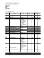
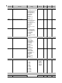
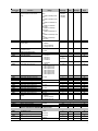
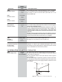
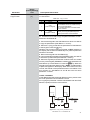
Motors | Automation | Energy | Transmission & Distribution | Coatings Soft-Starter SSW-07 / SSW-08 Programming Manual Programming Manual Series: SSW-07 / SSW-08 Language: English Document Number: 0899.5665 / 08 Software Version: V1.5X Publication Date: 08/2015 SUMMARY QUICK PARAMETER REFERENCE FAULT AND STATUS MESSAGES ............................................... 4 l. PARAMETERS TABLE ....................................................................................................................... 4 ll. FAULTMESSAGES ............................................................................................................................ 9 lll. OTHER MESSAGES ........................................................................................................................ 9 1. GENERAL INFORMATION ................................................................................................................. 10 2. ABOUT THIS MANUAL ...................................................................................................................... 10 3. ABOUT THE SSW-07/SSW-08 .......................................................................................................... 10 4. ABOUT THE SSW-07/SSW-08 PARAMETER PROGRAMMING ....................................................... 10 5. KEYPAD(HMI) USE ........................................................................................................................... 10 5.1. LEDs Display Functions .............................................................................................................. 11 5.2. Function of the “Local” and “Remote” LEDs ................................................................................. 11 5.3. Function of the Direction of Rotation LEDs (Clockwise and Counterclockwise) ........................... 11 5.4. Basic Functions of the Keys ....................................................................................................... 12 5.5. Signaling/Indications on the Keypad Display ............................................................................... 12 5.6. Parameter Viewing/Changing ....................................................................................................... 12 6. DETAILED DESCRIPTION OF THE PARAMATERS ........................................................................... 14 6.1. ACCESS AND READ ONLY PARAMETERS – P000 to P099 ...................................................... 15 6.2. REGULATION PARAMETERS - P100 to P199 ............................................................................ 17 6.3. CONFIGURATION PARAMETERS - P200 to P299 ...................................................................... 20 6.4. COMMUNICATION PARAMETERS – P300 to P399 .................................................................... 27 6.5. MOTOR PARAMETERS – P400 to P499 ..................................................................................... 29 6.6. PARAMETERS OF THE SPECIAL FUNCTIONS – P500 to P599 ................................................ 30 6.7. PROTECTION PARAMETERS – P600 to P699 ........................................................................... 31 7. ERRORS AND POSSIBLE CAUSES ................................................................................................. 37 QUICK PARAMETER REFERENCE FAULT AND STATUS MESSAGES Software: V1.5x Application: Model: Serial Number: Responsible: Date: / / . I. PARAMETERS TABLE Parameter P000 P001 P002 P003 P005 P006 P007 P011 P012 P013 P014 P015 P016 P017 P020 P023 P030 P031 P032 P050 P081 P090 P091 P092 P093 P094 P095 P096 P101(3) Function Access to parameters READ ONLY PARAMETERS Motor current %In of SSW-07/SSW-08 Motor current %In of Motor Motor current Power supply frequency Soft-Starter Status Voltage imposed by the Soft-Starter over the load (%Un) Apparent output power DI1 to DI3 status Adjustable Range 0 to 9999 P001 to P099 0.0 to 999.9 0.0 to 999.9 0.0 to 6553 0.0 to 99.9 0 = rdy - ready 2 = Exx - Error 3 = ruP - Ramp Up 5 = PASS - By-pass 7 = rdo - Ramp Down 8 = br - Braking 9 = rEv - FWD/REV 10 = JoG - Jog 11 = dly - Delay P630 12 = G.di - General Disable 0 to 100 0.0 to 999.9 0 = Inactive 1 = Active Relay RL1 and RL2 output status 0 = Inactive 1 = Active Last fault occurred E00 to E77 Second fault occurred E00 to E77 Third fault occurred E00 to E77 Fourth fault occurred E00 to E77 Actual Fault 0...99 Software version x.xx Phase R current 0.0 to 6553 Phase S current 0.0 to 6553 Phase T current 0.0 to 6553 Motor thermal protection status 0 to 250 Heatsink temperature 10.0 to 110.0 CAN Controller Status 0 = Inactive 1 = Autobaud 2 = Active CAN Interface 3 = Warning 4 = Error passive 5 = Bus off 6 = No Bus Power DeviceNet Network Status 0 = Offline 1 = Online, Not Connected 2 = Online, Connected 3 = Expire Connection 4 = Connection Failure 5 = Auto-Baud DeviceNet Master Status 0 = Run 1 = Idle Received CAN Telegram Counter 0 to 9999 Transmitted CAN Telegram Counter 0 to 9999 Buss Off Error Counter 0 to 9999 Lost Can Message Counter 0 to 9999 REGULATION PARAMETERS P100 to P199 Ramps Initial voltage (%Un) 30 to 90 Factory Settings 0 (5) Unit User’s Settings Page - 15 - % 15 - % A Hz - 15 15 15 15 - % 15 - kVA - 15 15 - - 16 - A A A % ºC - 16 16 16 16 16 16 17 17 17 17 17 17 - - 17 - - 17 - - 17 17 17 17 50 % 17 4 Parameter Function Adjustable Range 1 to 999 P102(3) Acceleration ramp time P103 Deceleration Voltage Step (% Un) P104(3) Deceleration ramp time P105 P200 End Deceleration Voltage (% Un) Current Limitation Current limitation (%In of the Soft-Starter) Initial Current for Current Ramp (%In of the Soft-Starter) Time for the Current Ramp (% of P102) CONFIGURATION PARAMETERS Generic Parameters The password is P202 Type of Control P203 Fan Control P204(1) Load parameters with factory default values P205 Reading parameter selection 0 = Inactive 1 = Active 0=Voltage Ramp 1=Current Limit 2=Pump Control 3=No Function 4=Current Ramp 5=Direct Online (DOL) 0 = Fan is always OFF 1 = Fan is always ON 2 = Fan controlled by software 0 = No function 1 = No function 2 = No function 3 = No function 4 = No function 5 = Loads factory default values 0 to 999 P206 Auto-reset time 3 to 1200 P207(3) Auto-reset P215(1) Copy function P219 Parameterization via Keypad / (Trimpots and DIP Switch) 0 = Inactive 1 = Active 0 = Inactive 1 = SSW Keypad 2 = Keypad SSW 0=Trimpots and DIP Switch 1=Keypad 2=P202=2 / Trimpots and DIP (3) P110 P111 P112 P220(1) Local/Remote Definition Local/remote supply selection P229(1) Command selection – local situation P230(1) Command selection – remote situation 100 = Inactive 99...60 0=Inactive 1 to 240 30...55 Factory Settings 20 Unit User’s Settings Page s 18 100 % 18 0=Inactive s 19 30 % 19 30 to 500 300 % 19 30…500 150 % 19 20 % 20 1…99 P200 to P299 0 = Always local 1 = Always remote 2 = Keypad (local default) 3 = Keypad (remote default) 4 = DI1 to DI3 5 = Serial (local default) 6 = Serial (remote default) 7 = Fieldbus (Default Local) 8 = Fieldbus (Default Remote) 0 = Keypad 1 = Digital Input DIx 2 = Serial 3 = Fieldbus 0 = Keypad 1 = Digital Input DIx 2 = Serial 3 = Fieldbus 1 = Active - 20 0 - 21 2 = Fan controlled by software - 22 0 = No function 22 - 1 = P001 - 22 900 s 22 0 = Inactive 22 0 = Inactive - 23 0 - 24 3 = Keypad (default remote) - 24 0 = Keypad - 24 1 = Digital Input DIx - 24 5 Parameter Function Adjustable Range Factory Settings Unit User’s Settings 0=No Function 1=Start/Stop (two wires) or Start (three wires) 2=Local/Remote 3=No External Fault 4=FWD/REV 5=Brake Off 6=Reset 7=No Function 8=Jog 0=No Function 1=Stop (Three-wires) 2=Local/Remote 3=No External Fault 4=FWD/REV 5=Brake Off 6=Reset 7=Emergency Start 8=Jog 0 = No function 1 = General enable 2 = Local/Remote 3 = No external fault 4 = FWD/REV 5 = Brake off 6 = Reset 7 = Emergency Start 8 = Jog 1 - 25 6 - 25 6 = Reset - 25 Page Digital Inputs P263 Digital Input DI1 Function P264 Digital Input DI2 Function P265(1) Input DI3 function Relay Outputs P277 P278 RL1 Relay Function RL2 Relay Function 0=No Function 1=Running 2=Full Voltage 3=No Function 4=FWD/REV - K1 5=DC-Brake 6=No Fault 7=Fault 8=No Function 9=Serial 13=Shunt Trip 0=No Function 1=Running 2=Full Voltage 3=No Function 4=FWD/REV - K2 5=DC-Brake 6=No Fault 7=Fault 8=No Function 9=Serial 13=Shunt Trip 1 26 - 2 - 26 According to the SoftStarter SSW-07/ SSW-08 nominal current A 27 1 - 27 Soft-Starter Data P295(1)(2) Nominal current COMMUNICATION PARAMETERS 0 = 1.7A 1 = 17A 2 = 24A 3 = 30A 4 = 45A 5 = 61A 6 = 85A 7 = 130A 8 = 171A 9 = 200A 10 = 255A 11 = 312A 12 = 365A 13 = 412A P300 to P399 Serial Communication P308(1)(2) Soft-Starter address 1 to 247 6 Parameter (1)(2) Function Adjustable Range Factory Settings 1= Modbus 9600bps no parity - 27 Unit User’s Settings Page P312 Type of protocol and serial communication transmission rate 1 = Modbus 9600bps no parity 2 = Modbus 9600bps odd parity 3 = Modbus 9600bps even parity 4 = Modbus 19200bps no parity 5 = Modbus 19200bps odd parity 6 = Modbus 19200bps even parity 7 = Modbus 38400bps no parity 8 = Modbus 38400bps odd parity 9 = Modbus 38400bps even parity P313 Serial communication error action (E28) 0 = Inactive 1 = Disable 2 = General disable 3 = Change to local 1 = Disable - 28 Serial communication verification time 0 = Inactive 1 to 999 0 = Inactive s 28 28 28 (3) P314 P331 P332 P333 P335 P336 P337 P338 P339 P340 P341 P342 P343 P344 P345 P346 P347 P348 P400(1) P401(1)(3) P406(1) P501 P502 P510 P511 Fieldbus Communication CAN Address CAN Baud Rate 0 to 63 0 = 125 Kbps 1 = 250 Kbps 2 = 500 Kbps 3 = Autobaud Bus Off Reset 0 = Manual 1 = Automatic DeviceNet I/O Instances 0 = ODVA 1 = WEG Specific 1W 2 = WEG Specific 2W 3 = WEG Specific 3W 4 = WEG Specific 4W 5 = WEG Specific 5W 6 = WEG Specific 6W 7 = WEG Specific 7W DeviceNet Reading Word #2 0 to 999 DeviceNet Reading Word #3 0 to 999 DeviceNet Reading Word #4 0 to 999 DeviceNet Reading Word #5 0 to 999 DeviceNet Reading Word #6 0 to 999 DeviceNet Reading Word #7 0 to 999 DeviceNet Writing Word #2 0 to 999 DeviceNet Writing Word #3 0 to 999 DeviceNet Writing Word #4 0 to 999 DeviceNet Writing Word #5 0 to 999 DeviceNet Writing Word #6 0 to 999 DeviceNet Writing Word #7 0 to 999 Fieldbus communication error 0 = Inactive action 1 = Disable 2 = General Disable 3 = Change to local MOTOR PARAMETERS P400 to P499 Nominal Parameters Motor nominal voltage 1 to 999 Motor current setting 30.0 to 100.0 Service factor 1.00 to 1.50 SPECIAL FUNCTIONS PARAMETERS P500 to P599 Braking DC Braking Time 0...299 0=Inactive DC Braking Voltage Level 30...70 Jog 0=Inactive 1=Active Jog Level 30...70 63 - 3= Autobaud - 0 = Manual - 0 = ODVA 28 28 - 0 0 0 0 0 0 0 0 0 0 0 0 1 = Disable - 28 28 28 28 28 28 28 28 28 28 28 28 28 - 380 100.0 1.00 V % - 29 29 29 0 s 29 30 0 % - 29 30 30 % 30 7 Parameter P520(1)(3) P521(3) P522 P610(1) P611(1) (3) P612(1) P613(1) (3) P614(1) P615 (1) P616 (1) P617 (1)(3) P620(1) (3) P621 P622(1) Adjustable Range Function Kick Start Voltage pulse at start (Kick Start) Pulse time at start 0 = Inactive 1 = Active 0.2 to 2.0 Voltage pulse level at start 70 to 90 (%Un) PROTECTION PARAMETERS P600 to P699 Current Protections Phase Loss or Immediate 1 to 80 Undercurrent (% In of the Motor) Immediate undercurrent time or 0 = Inactive phase loss 1 to 99 Immediate overcurrent (%In of 1 to 200 motor) Immediate overcurrent time 0 = Inactive 1 to 99 Current imbalance between 0 to 30 phases (%In of motor) Current imbalance time between phases Undercurrent before By-Pass closing Blocked Rotor Phase Sequence RST phase sequence E77 Enabling SSW Short Circuit Detection SSW short circuit 0 = Inactive 1 to 99 0 = Inactive 1 = Active 0 = Inactive 1 = Active 0= 1= 0= 1= Inactive Active Inactive Active 0 = Inactive 1 = Active Factory Settings Unit User’s Settings Page 0 = Inactive - 0.2 s 30 80 % 30 80 % 31 1 s 31 100 % 31 1 s 31 15 % 32 0 = Inactive s 32 0 = Inactive - 32 1 = Active - 32 1 = Active - 32 1 = Active - 32 0 = Inactive 30 32 Interval Between Starts P630 Time interval after stopping 2 to 999 2 s 33 6 = 30 - 34 0 = Inactive s 36 Motor Thermal Protection P640(1) (3) Motor protection thermal class P641(1) Thermal memory auto-reset 0 = Inactive 1=5 2 = 10 3 = 15 4 = 20 5 = 25 6 = 30 0 = Inactive 1 to 600 (1) Changeable parameters only when the motor is disabled. (2) Unchanged parameters at factory default settings (P204=5). (3) Changeable parameters only in keypad mode (P219=1). If P219=0 the parameters are read only. 8 ll. FAULT MESSAGES Indication Meaning Page E03 Phase loss or undercurrent 37 E04 Overtemperature on power 37 E05 Overload on motor 37 E06 External fault (DI) 38 E10 Function copy fault 38 E19 SSW short circuit 38 E24 Programming fault 38 E28 Timeout fault at telegram reception 38 E31 Keypad connection failure 38 E62 Current limitation start timeout 38 E63 Stall 38 E66 Overcurrent 39 E67 Inverted phase sequence 39 E70 Undervoltage at electronic supply 39 E71 By-pass contact open 39 E72 Overcurrent before By-pass 39 E74 Current imbalance 39 E75 Power supply frequency out of allowed range 40 E76 Undercurrent before closing By-pass 40 E77 Closed by-pass contact or shorted SCR’s 40 lll. OTHER MESSAGES Indication rdy ruP PASS rdo Meaning Soft-Starter ready to be on “ready” Soft-Starter on, at acceleration ramp “ramp up” Soft-Starter on, at By-Pass “by-pass” Soft-Starter on, at deceleration ramp “ramp down” Exx Soft-Starter with error dly Soft-Starter waiting for time after stop “delay” G.di Soft-Starter with general disable “general disable” 9 1. GENERAL INFORMATION This manual contains the necessary information for the correct use of the Soft-Starter SSW-07/ SSW-08. It was written to be used by trained or technically qualified people to operate this type of equipment. 2. ABOUT THIS MANUAL This manual gives the necessary description for the configuration of all the functions and parameters of the Soft-Starter SSW-07/SSW-08. This manual must be used together with the SSW-07/ SSW-08 User’s Guide. 3. ABOUT THE SSW-07/SSW-08 The Soft-Starter SSW-07/ SSW-08 is a high performance product that allows start control of three phase induction motors. This way mechanic shocks in the load and current surges in the power supply can be avoided. 4. ABOUT THE SSW-07/SSW-08 PARAMETER PROGRAMMING The basic functions of the Soft-Starter SSW-07/SSW-08 can be programmed at the front cover at the SSW-07/SSW-08 (Trimpots and DIP Switch). To program additional functions and/or visualize reading parameters, some accessories must be used, as for example: the Software SuperDrive G2, Serial Communication RS-232 or RS-485, Local or Remote Keypad. For more details see the chapter 7 of the User’s Guide and the optionals guides of SSW-07/SSW-08. NOTE! For communication with the SSW-07/SSW-08 use the 2nd generation programming software SuperDrive G2. The first generation software named SuperDrive is not compatible with this product. Parameter P219, Parameterization via Keypad/ (Trimpots and DIP Switch), defines the programming origin for the protection and acceleration/deceleration ramps. A Soft-Starter SSW-07/ SSW-08 can be programmed via Trimpots and DIP Switches or completely via parameters. See the detailed description of parameters (P219). Parameters P220, P229, and P230 (Local/Remote Definitions) program the origin of the enable/ disable command. Factory default settings enable via digital input. To enable/disable by means of keypad or serial command the settings of P220, P229 and P230 must be changed. See the detailed description of parameters P220, P229 and P230. The SSW-07/SSW-08 User’s Guide has a chapter dedicated to Programming Suggestions. It’s important to read this chapter before starting to program the Soft-Starter SSW-07/SSW-08. 5. KEYPAD(HMI) USE The keypad is a simple interface that allows the operation and the programming of the Soft-Starter. It presents the following functions: - Indication of the Soft-Starter operational status; - Indication of the errors; - Visualization and modification of the adjustable parameters; - Operation of the soft-Starter ( and keys). 10 The keypad can be used in the following cases: - If an keypad for commanding, programming and/or visualizing SSW-07/SSW-08 parameters were necessary; - For installation of the keypad at the cabinet door, commanding panel or at the SSW-07/SSW-08 front cover; - When the copy function were necessary. The SSW-07/SSW-08 local or remote keypad presents a 7-segment 4-digit LED display, 4 status LEDs and 8 keys. The figures below show a front view of the remote keypad and of the local keypad. Figure 5.1 a) - Remote Keypad Front View Figure 5.1 b) - Local Keypad Front View 5.1. LEDs Display Functions It shows the parameter number or its content and also fault and status messages. 5.2. Function of the “Local” and “Remote” LEDs Soft-Starter in Local mode: Green LED on and red LED off. Soft-Starter in Remote mode: Green LED off and red LED on. 5.3. Function of the Direction of Rotation LEDs (Clockwise and Counterclockwise) Refer to figure below. Figure 5.2 - Direction of Rotation (FWD / REV) LEDs 11 5.4. Basic Functions of the Keys - Enables the motor (start); - Disables the motor (stop). Resets the Soft-Starter after the occurrence of errors; - Selects (toggles) the display between the parameter number and its value (position/content); - Increments the parameter number or the parameter value; - Decrements the parameter number or the parameter value; - Selects the origin of the commands between Local or Remote; - Reverses the direction of motor rotation between Forward/Reverse; - Performs the JOG function when pressed. Any DIx programmed for General Enable must be closed (and the Soft-Starter must be stopped) to enable JOG function. 5.5. Signaling/Indications on the Keypad Display Soft-Starter states: Soft-Starter ready to enable the motor Soft-Starter in an error condition. The error code shows up flashing. In the example we have the E03 indication (phase Loss). Soft-Starter executing the function “Load parameters with the factory default (P204)”. NOTES! The display also flashes in the following situations, besides the error condition: An attempt to change a parameter with an incorrect password (P000 – Access parameter); An attempt to change a not allowed parameter. For instance one that cannot be changed with the motor rotating. 5.6. Parameter Viewing/Changing All the settings of the Soft-Starter can be done through the parameters. The parameters are indicated on the display by means of the letter P followed by a number: Example (P264): 264 = number of the parameter There is a numeric value (content of the parameter) associated to each parameter, which corresponds to the option chosen among the available ones for that parameter. The values of the parameters define the Soft-Starter programming or the value of a variable (E.g.: current, voltage). In order to carry out the soft-Starter programming one must change the content(s) of the parameter(s). 12 Example: ACTION KEYPAD DISPLAY DESCRIPTION Soft-Starter is ready to operate To power up a Soft-Starter Press Use the and Locate the desired parameter keys Numeric value associated to the (2) parameter Press Use the and Adjust the new desired value keys (2) (1) (2) (3) Press NOTES! (1) By pressing the key after an adjustment, the last adjusted value is automatically stored in the Soft-Starter nonvolatile memory, being kept until a new modification. (2) In order to be able to change the value of a parameter, it is necessary to set first P000 = 5. Otherwise it will only be possible to see the parameters, but not changing them. For more details refer to the P000 description. (3) If the last value programmed in the parameter is not functionally compatible with other parameter values already programmed, an E24 –Programming Error -will be displayed. Example of programming error: Programming two digital inputs (DIx) with the same function. Refer to Table 5.1 for the list of programming errors that will generate an E24 Programming Error. E24 - Programming Error Table 5.1 - Incompatibility between Parameters - E24 Two or more parameters between P263 and P265 equal to 2 (LOC/REM); Two or more parameters between P263 and P265 equal to 4 (Rotation direction); Two or more parameters between P264 and P265 equal to 7 (Emergency Start); Two or more parameters between P263 and P265 equal to 8 (Jog); If programmed Emergency Start with Rotation direction changing, DC Braking or Jog; (P202 = 3) if the Control Type is programmed to 3 (no function). 13 6. DETAILED DESCRIPTION OF THE PARAMATERS The parameters have been grouped by types to make description easier. Reading Parameters Regulation Parameters Variables that can be seen but not changed by the user. Adjustable values to be used the Soft-Starter functions. Configuration Parameters Define the Soft-Starter SSW-07/SSW-08 characteristics, the functions to be carried out, as well as the input/output functions of the control card. Motor Parameters The catalog data or motor plate. Special Functions Parameters Protection Parameters Include the parameters related to the special functions. Parameters related to the action and time levels of the motor protections. Symbols and definitions used in this chapter: (1) Changeable parameters only when the motor is disabled. (2) Unchanged parameters at factory default settings (P204=5). (3) Changeable parameters only in keypad mode (P219=1). If P219=0 the parameters are read only. 14 6.1. ACCESS AND READ ONLY PARAMETERS – P000 to P099 Parameter Range [Factory Setting] Unit Description/ Notes 0 to 9999 [0] - Permits the access to alter the contents of the parameters. Set with factory default values [P200=1 (Active Password)] it is necessary to out P000=5 to change the contents of the parameters. P001 Motor current %In of SSW-07/ SSW-08 0.0 to 999.9 [-] 0.1% Indicates the Soft-Starter SSW-07/SSW-08 output current at the nominal current percentage of the Soft-Starter (%In of SSW-07/ SSW-08). Accuracy of ±2% for full scale. (Full scale is 5 x In of SSW-07/ SSW-08. P002 Motor current %In of Motor 0.0 to 999.9 [-] 0.1% Indicates the Soft-Starter SSW-07/SSW-08 output current at the nominal current percentage of the Motor (%In of Motor). Accuracy of ±2% for full scale. (Full scale is 5 x In of SSW-07/ SSW-08). P003 Motor current 0.0 to 6553 [-] 0.1A Indicates the Soft-Starter SSW-07/SSW-08 output current in Amperes (A). Accuracy of ±2% for full scale. (Full scale is 5 x In of SSW-07/ SSW-08). P005 Power supply frequency 0.0 to 99.9 [-] 0.1Hz Indicates the power supply frequency in Hertz (Hz). Accuracy of ±5% of the power supply nominal frequency. P000 Access to parameters P006 Soft-Starter Status 0 to 12 [-] - Indicates the current status of the Soft-Starter SSW-07/ SSW-08. 0= rdy – Ready to be on “ready”. 2= Exx – With error. 3= ruP – Turned on at acceleration ramp “ramp up. 5= PASS – On with enabled “by-pass”. 7= rdo – On at deceleration ramp “ramp down. 8= br – Performing braking "braking". 9= rEv – Performing reversion of the speed direction "reverting". 10 = rdo – On at deceleration ramp “ramp down. 11 = JoG – During Jog "Jog". 12 = G.di – With “general disable”. P007 Voltage imposed by the Soft-Starter over the load (%Un) 0 to 100 [-] 1% Indicates the voltage imposed by Soft-Starter over the load, not taking stator emf generated by the motor into consideration. P011 Apparent output power 0.0 to 999.9 [-] 0.1kVA Indicates the apparent power of the average of the three Soft-Starter SSW-07/SSW-08 output phases in kiloVolt Amperes (kVA). P012 DI1 to DI3 Status 0 to 224 DisplayLED= 0 or 1 [-] - Indicates the status of the three control card digital inputs (DI1 to DI3). On the keypad display the digital inputs status is shown by numbers 0 = Inactive and 1 = Active in the following order, DI1, DI2 and DI3. The indication is binary and DI1 represents the most significant bit. The 5 less significant bits are not shown on the keypad display. Example: DI1 = Active DI2 = Inactive DI3 = Active 15 Parameter Range [Factory Setting] Unit Description/ Notes Which is the equivalent to the sequence of bits: 10100000b. In decimal it corresponds to 160. The binary indication on the keypad is: P013 Relay RL1 and RL2 output status 0 to 192 DisplayLED= 0 or 1 [-] - Indicates the status of the 2 control card relay outputs RL1 and RL2). On the keypad display the relay output status is shown by numbers (0 = Inactive) and (1= Active), in the following order, RL1 and RL2. The indication is binary and RL1 represents the most significant bit. The 5 less significant bits are not shown on the keypad display. Example: RL1 = Active RL2 = Active Which is the equivalent to the sequence of bits: 11000000b. In decimal it corresponds to 160. The binary indication on the keypad is: P014 Last fault occurred E00 to E77 [-] - P015 Second fault occurred E00 to E77 [-] - P016 Third fault occurred E00 to E77 [-] - P017 Fourth fault occurred E00 to E77 [-] - P020 Actual Fault 0 to 99 [-] - It indicates if any fault is active. X . XX [-] - Indicates the Software version in the microcontroler memory (DSP) on the control board. P023 Software Version Indicates the numbers of the last, second, third and fourth previous faults occurred, respectively. Registration systematic: Exy P014 P015 P016 P017 NOTE! Faults related to communication, E28, are not indicated in P020. 16 Parameter Range [Factory Setting] Unit P030 Phase R current 0.0 to 6553 [-] 0.1A P031 Phase S current 0.0 to 6553 [-] 0.1A P032 Phase T current 0.0 to 6553 [-] 0.1A P050 Motor thermal protection status 0 to 250 [-] 1% P081 Heatsink temperature P090 to P096 Parameters Regarding the DeviceNet Communication 10.0 to 110.0 [-] 0.1 oC - Description/ Notes Indicates the output currents of phases R, S and T in Amperes. The True RMS current is indicated individually for each phase. Accuracy of ±2% for the full scale. (Full scale is 5 x In of SSW-07/SSW-08). Indication of the state of motor thermal protection in a scale of 0% to 250%. Being 250 the thermal protection functioning point of the motor, indicating an error. The value indicated in this parameter depends on the motor working condition and how long it has been in this condition, for example:stopped, starting or in full operation. The thermal class selected and the nominal power of the motor also influence in this parameter. Only a value of approximately 160 can be read if the motor is operating in full load for over 2 hours with a current equal to the nominal current times the service factor (In x S.F.@2h). Indicates the SCR heatsink temperature in ºC. Range: 10.0°C (50.0°F) to 110.0°C (230.0°F). Parameters for the DeviceNet interface configuration and operation. In order to get a detailed description, refer to the DeviceNet Communication Manual, supplied in electronic format on the CD-ROM that comes with the product. 6.2. REGULATION PARAMETERS - P100 to P199 P101 Initial voltage (%Un) 30 to 90 [ 50 ] 1% Un do Motor Used in the control by Voltage Ramp and Pump Controls. Sets the initial value of nominal voltage (%Un) that will be applied to the motor as in figure 6.1. This parameter must be set to the minimum value to get the motor rotating. The initial voltage is applied at a greater or equal to 0.5s after the Soft-Starter receives the command to start on the motor. This is the delay time for the power supply isolation contactor to close the contacts. U(V) Start P101 0 0.5s P102 Enable Figure 6.1 - Initial time in a start with voltage ramp 17 Parameter P102 Acceleration ramp time Range [Factory Setting] Unit 1 to 999 [ 20 ] 1s Description/ Notes When the Soft-Starter is programmed with Voltage Ramp, Pump Control or Direct Online control, this is the voltage increment ramp time, as seen in the figure 6.2. U(V) Start 100%Un P101 0 t(s) P102 Enable Voltage Ramp Disable Figure 6.2 - Acceleration ramp by voltage ramp When the Soft-Starter is programmed with Current Limitation or Current Ramp control, this time serves as the maximum starting time, operating as a protection against blocked rotor. I(A) Start I Limitation P110 I Nominal 0 Maximum Time Enable P102 Current Limitation t(s) Disable Figure 6.3 - Current limitation acceleration ramp NOTE! The time programmed at P102 is not the exact motor acceleration time, but, the voltage ramp time or the maximum starting time. The motor acceleration time will depend on the motor characteristics as well as the load. P103 Deceleration voltage step (% Un) 100 = Inactive 99 to 60 [100] 1% Used in applications with hydraulic pumps. Sets the nominal voltage value (%Un) that will be applied to the motor immediately after the Soft-Starter receives the deceleration by ramp command. NOTE! For this function to turn on a deceleration ramp time must be programmed. 18 Parameter P104 (3) Deceleration ramp time Range [Factory Setting] Unit 0 = Inactive 1 to 240 [0] 1s Description/ Notes Used in applications with hydraulic pumps. Enables and sets the voltage decrement ramp time. NOTE! This function is used to lengthen the normal deceleration time of a load and not to force a lower time than the one imposed by the load. P105 End Deceleration Voltage 30 to 55 [ 30 ] 1% Used in hydraulic pump applications. Sets the nominal voltage (%Un), which will be applied to the motor at the end of the deceleration ramp. For more details about the programming and use, refer to Pump Control at P202. U(V) 100%Un Stop P103 P105 0 P104 t(s) Disable Voltage Ramp Figure 6.4 - Deceleration ramp by voltage decrement P110 (3) Start by current limitation (%In of the Soft-Starter) 30 to 500 [ 300 ] 1%In of the Soft-Starter Defines the maximum current limit during a motor start as a percentage of the Soft-Started nominal current. If the current limit is reached during the motor start, the Soft-Starter will maintain the current of this limit until the motor reaches the end of the start. If the current limit is not reached, the motor will start immediately. To select the Control by Current Limitation, see P202. P111 Initial Current for Current Ramp (%In of the Soft-Starter) 30 to 500 [150] 1% In of the Soft-Starter Used for the control by Current Ramp, P202=4. Allows a current limit ramp to be programmed to help in the starting of loads that have a lower or higher starting torque. The initial value of the current limit is shown by P111, the final value is shown by P110 and the time is shown by P112. 19 Parameter P112 Time for the Current Ramp (% de P102) Range [Factory Setting] Unit 1 to 99 [20] 1% of P102 Description/ Notes Used for the control by Current Ramp, P202=4. It enables programming the time, in percent of P102, for the end Current Ramp. After the time, programmed at P112, has elapsed, it starts operation by Current Limit, given by P110. I(A) Start P110 Nominal Current I Limit P111 0 P112 P102 Maximum Time Enable t(s) Current Ramp Disable Figure 6.5 a) - Current Limit by Current Ramp during Starting I(A) Start P110 P111 I Limit 0 Nominal Current P112 P102 Maximum Time Enable t(s) Current Ramp Disable Figure 6.5 b) - Current Limit by Current Ramp during Starting 6.3. CONFIGURATION PARAMETERS - P200 to P299 P200 The password is (activate/deactivate password) 0 or 1 [1] - Table 6.1 - Enabling the password P200 0 (Inactive) 1 (Active) Action Allows the parameter contents to be altered independent of P000. Only allows parameter content alterations when P000 is equal to the password value. The value of the password is P000=5. 20 Parameter P202 Type of control Range [Factory Setting] Unit 0 to 5 [ 0=Voltage Ramp] - Description/ Notes Table 6.2 - Type of control P202 0 1 2 3 4 5 Description Voltage ramp Current limitation Pump control No function Current ramp Direct online Start (DOL) Soft-Starter SSW-07/SSW-08 has five types of starting controls to best adapt itself to the needs of its application. Starting with voltage ramp: This is the most commonly used method. The Soft-Starter imposes the voltage on the motor without any kind of voltage or current feedback applied to the motor. This is applied to loads with lower initial torques or quadratic torques. This kind of control can be used as an initial working test. Starting by current limitation: The maximum current level is maintained during the start, being set according to the needs of the application. Applied to loads with higher initial torques or constant torques. This type of control is used to adapt the start to the capacity limits of the supply network. Start by Pump Control: This type of control provides the required torque for starting and stopping hydraulic centrifugal pumps smoothly. It has a special algorithm for application in centrifugal pumps, where loads with quadratic torques are present. This special algorithm aims to minimize pressure overshoots in the hydraulic piping, which can result in breakdown or excessive pump wearing. Start by Current Ramp: The maximum current level is limited during the start process, however higher or lower current limits can be set during the beginning of the start sequence. It can substitute the kick start functions for loads with higher initial torques. This type of control is used for loads with lower or higher initial torques. This type of control is used to match the start process to the limits of the power supply capacity. Direct online start (DOL): The Soft-Starter imposes 100% of voltage on the motor without any kind of voltage or current feedback applied to the motor. This method is applied only in special cases, where is required 100% of voltage on the motor during the motor starting. 21 Parameter P203 Fan Control Range [Factory Setting] Unit 0 to 2 [2] - Description/ Notes P203 defines the operation mode of the heatsink cooling fan. The ventilation kit is an option. Refer to the Optional Devices Chapter on the User Manual. The SSW-07/SSW-08 from 17 to 30A models do not need the ventilation kit. When in the “fan controlled by software” mode (P203 = 2), the fan is switched ON when the SCR’s are conducing or when the heatsink temperature is higher than 65°C. The fan is switched OFF when the SCR’s are not conducing and the temperature is lower than 55°C. Table 6.3 - Options for the fan control P203 0 1 2 P204 (1) Loads parameters with factory default values 0 to 5 [0] - Action The Fan is always OFF The fan is always ON The fan is controlled by soft ware Reprograms all the parameters to the factory default values, making P204=5. Parameters P000, P295, P308 and P312 are not changed when P204=5 (factory default). Table 6.4 - Loads parameters with factory default P204 Action 0 to 4 No function 5 Loads factory default P205 Selection of the reading parameter 0 to 999 [1] - Selects which parameters will be shown on the display after the Soft-Starter is energized. The value programmed at P205 is equal to the parameter number that will be shown on the display after it is energized. If the programmed value corresponds to a non-existent parameter, the adopted value will be 1=P001. P206 Auto-Reset time 3 to 1200 [ 900 ] 1s When an error occurs, except for E04, E10, E19, E24, E28, E3x, E67 and E77, the Soft-Starter will reset automatically, after passing the time given by P206. After the auto-reset, if the same error occurs again three times consecutively, the auto-reset function will be inhibited. If an error appears again up to 30 seconds after the auto-reset is executed, it is considered to be a reoccurrence, Therefore, if an error occurs four times consecutively, this error will continue being indicated (and the Soft-Starter will continue to be disabled) permanently. NOTE! For Electronic Motor Overload and Power Overtemperature there is a specific algorithm for the automatic reset time. P207 (3) Auto-Reset 0 to 1 [0=Inactive] Table 6.5 - Auto-Reset Selection P207 0 1 Description Inactive Active 22 Parameter P215 (1) Copy function Range [Factory Setting] Unit 0 to 2 [0] - Description/ Observation The copy function is used to transfer the parameter contents of a Soft-Starter. P215 0 1 2 Table 6.6 - Copy function Explanation Transfers the present parameter contents of the Soft-Starter to the non-volatile memory Copy of the keypad (EEPROM). (SSW Keypad) The present parameters of the Soft-Starter remain unaltered. Transfers the contents of the non-volatile Paste memory of the keypad (EEPROM) to the (Keypad SSW) present parameters of the Soft-Starter. Action Inactive Procedure to be used to copy the parameterization of SoftStarter A to Soft-Starter B: 1. Connect the keypad to the Soft-Starter from which one wishes to copy the parameters (Soft-Starter A – source). 2. Set P215=1 (copy) to transfer the parameters of Soft-Starter A to the keypad. Press the key . While the copy function is being processed, “COPY” appears on the display. P215 returns automatically to 0 (Inactive) when the transfer is concluded. 3. Remove the keypad from Soft-Starter (A). 4. Connect this same keypad to the Soft-Starter which one wishes to transfer the parameters (Soft-Starter B – destiny). 5. Set P215=2 (paste) to transfer the contents of the non-volatile memory of the keypad (EEPROM- containing the parameters of key. While the Soft-Starter A) to Soft-Starter B. Press the keypad is processing the paste function, “PAST”, an abbreviation of paste, will appear on the display. When P215 returns to 0 and is reset, the transfer of the parameters will be concluded. From this moment on, Soft-Starters A and B will have the same parameter contents. Please remember: If Soft-Starters A and B command different motors, please check the motor parameters of Soft-Starter A and B. For copying the parameter contents of Soft-Starter A to other SoftStarters, repeat procedures 4 and 5 above. Soft-Starter B Soft-Starter A Parameters Parameters SSW Keypad (copy) P215=1 Keypad SSW (paste) P215=2 Press. EEPROM HMI Press. EEPROM HMI Figure 6.6 - Copy of the parameters from “Soft-Starter A” to “Soft-Starter B” 23 Parameter Range [Factory Setting] Unit Description/ Notes NOTE! If the Keypad has saved parameters of a “different version” than that installed in Soft-Starter SSW-07/SSW-08 to which it is trying to copy the parameters, the operation will not be executed and Soft-Starter SSW-07/SSW-08 will display error E10 (Error: Copy Function not permitted). “Different Version” are those that are different in “x” or “y”, supposing that the numbering of Software Versions is described as Vx.yz. P219 (1) Parameterization via keypad / (Trimpots and DIP Switch) 0 to 2 Defines the programming mode of the following parameters: [ 0=Trimpots and P101, P102, P104, P110, P202, P207, P401, P520, P521, P611, DIP Switch] P613, P617, P620 and P640. These parameters are marked in the quick parameter reference with the observation (3). 0 – “(Trimpot and DIP Switch) Mode”, programming of the parameters mentioned above is done through the Trimpots and DIP Switches. The parameters function as reading parameters, only showing the programmed values through Trimpots and DIP Switches. The values programmed through serial communication are not used. 1 – “Keypad Mode”, programming of the parameters mentioned above is done through serial communication or keypad. The values set in the Trimpots and DIP Switches are not used. 2 - "P202=2 / Trimpot and DIP", use this mode only when the pump control is required and there is not available a Keypad or serial communication. In this mode, the parameterization is done through Trimpots and DIP Switch. The control type is set to pump control, ignoring the setting of the DIP Switch "Voltage Ramp / Current Limit". The item 5.1.4 of the User's Manual, explain how to program P219 without Keypad or serial communication. P220 (1) LOCAL/REMOTE Source Selection 0 to 8 Defines the supply origin of the command that will select [ 3 = Keypad between the Local and Remote situations. (Remote Default) ] Table 6.7 – Local/remote origin P220 0 1 2 3 4 5 6 7 8 P229 (1) Command selection – local situation P230 (1) Command selection – remote situation 0 to 3 [ 0 = Keypad ] - Local/Remote Selection Always Local Situation Always Remote Situation “Loc/Rem” Keypad “Loc/Rem” Keypad Digital inputs DI1 to DI3 Serial Communication Serial Communication Fieldbus Fieldbus Default Situation Local Remote Local Remote Status DIx Local Remote Local Remote Default Situation = When the Soft-Starter is energized (initialization). Defines the origin of the on and off commands of the Soft-Starter. Table 6.8 – Origin of the motor on/off 0 to 3 [ 1 = Terminals ] - P229/P230 0 1 2 3 Origin of the Commands Keypad DIx Digital Inputs Serial Communication Fieldbus 24 Parameter P263 DI1 Input Function Range [Factory Setting] Unit 0 to 8 [1 = Start/Stop (Two wires) or Start (Three wires) ] - P264 DI2 Input function 0 to 8 [6 = Reset ] - P265 DI3 Input function 0 to 8 [6 = Reset ] - Description/ Notes Check the options available on table 6.8. The status of the digital inputs can be monitored in parameter P012. “Enable/Disable” = DI1 input is Closed/Open, respectively. Requires the programming of P263 = 1, P264 1 (Enable/Disable with two wires) and the programming of the Enable/Disable commands by digital input. “Start/Stop” = When programming P263 = 1 and P264 = 1 (Start/Stop with Three Wires), inputs DI1 and DI2 become DI1 = Start and DI2 = Stop. Use push button, DI1 Normally Open and DI2 Normally Closed. Requires the programming of the Enable/ Disable commands by digital input. “Local/Remote” = The digital input is Open/Closed, respectively. Do not program more than one digital input for this function. “Error Reset” = Resets the errors when the digital input is closed. Use only push button. When the input remains closed, the error reset will not act. “No External Error” = There is no external fault if the digital input is closed. “General Enable/General Disable” = The digital input is Closed/Open, respectively. This function allows the motor to turn on when it is on General Enable and to turn off the motor without a deceleration ramp when the General Disable command is given. There is no need to program general enable to turn on the motor via digital input. If general enable is programmed by digital input, then it must be closed to allow the motor to turn on, even if the commands are not by digital inputs. “Rotation Direction” = Digital input open K1 "on" and K2 "off", digital input closed K1 "off" and K2 "on". This enables the change control of the rotation direction through digital input. Do not program more than one digital input for this function. “Jog” = It is possible to enable slow speed with Jog via Digital Input when it is closed. Use a push-button only. Do not program more than one digital input for this function. “Brake Off” = It is possible to disable the braking methods when the digital input is open, for extra safety, monitor real motor stand still and disable the braking immediately. If more than one digital input is programmed for this function, any one which is opened disables the braking immediately “Emergency Start” = It makes possible start and stop the motor during any error action, not respecting the protections of Soft-Starter or the motor. This option is used for the hydraulical pumps of protection against fire. 25 Parameter Range [Factory Setting] Unit Description/ Notes NOTE! The Emergency Start only must be used in emergency case, otherwise the Soft-Starter or the motor may be damaged. Table 6.9 – Digital input functions DIx Parameter Function No Function Enable/Disable or Start (two or Three wires) Stop (Three wires) General Enable Local/Remote No External Fault Rotation Direction Brake Off Reset Emergency Start Jog P277 RL1 Relay function P278 RL2 Relay function 0 to 13 [ 1= Running ] - P263 (DI1) P264 (DI2) P265 (DI3) 0 0 0 1 - - 2 3 4 5 6 8 1 2 3 4 5 6 7 8 1 2 3 4 5 6 7 8 Check the options available on table 6.9. The status of the relay outputs can be monitored in parameter P013. When the function programmed for the relay output is true, the relay output will be turned on. 0 to 13 [ 2= Full Voltage ] “No Function” = Relay outputs always turned off. - “Running” = The output is turned on when the Soft-Starter receives an enabled signal. The output is turned off when the SoftStarter receives the turn off command, or at the end of the deceleration ramp, if it is programmed. “Full Voltage” = The output is turned on when the Soft-Starter reaches 100% Un and turned off when it receives an off command. “FWD/REV - K1” = this operation is similar to the "Running", but it must be enabled with forward motor direction of rotation. See the recommended setup at the User's Manual for more information. “FWD/REV - K2” = this operation is similar to the "Running", but it must be enabled with reverse motor direction of rotation. See the recommended setup at the User's Manual for more information. “DC-Braking” = the output will be enabled while the DC-Braking is active. See P501 and the recommended setup at the User's Manual for more information. “No Fault” = The output is enabled, if the Soft-Starter is not disabled due to any error. “Fault” = The output is enabled, if the Soft-Starter is disabled due to any error. “Serial” = See the Serial Communication Manual. “Shunt Trip” = When one of these errors are active, E03, E19, E66, E72 or E77, the output is turned on. 26 Parameter Range [Factory Setting] Unit Description/ Notes Function Table 6.10 – Relay output functions RLx Parameter P277 P278 (RL1) (RL2) No Function Running Full Voltage No Function FWD/REV - K1 FWD/REV - K2 DC-Braking No Fault Fault No Function Serial No Function No Function No Function Shunt Trip P295 (1)(2) Nominal current 0 to 13 [ According to the nominal current of the Soft-Starter SSW-07/ SSW-08 ] A 0 1 2 3 4 5 6 7 8 9 10 11 12 13 0 1 2 3 4 5 6 7 8 9 10 11 12 13 Table 6.11 – Nominal current configuration P295 Nominal Current (A) 0 1.7 1 17 2 24 3 30 4 45 5 61 6 85 7 130 8 171 9 200 10 255 11 312 12 365 13 412 ATTENTION! Never program this parameter with a current value that is not exactly like the one for your Soft-Starter SSW-07/SSW-08 model. If this parameter is programmed incorrectly it can damage the SoftStarter. P308 (1)(2) Soft-Starter address 1 to 247 [1] - Defines the Soft-Starter address in the Modbus-RTU serial communication network. For more details, see the Soft-Starter SSW-07/SSW-08 Serial Communication Manual. 6.4. COMMUNICATION PARAMETERS – P300 to P399 P312 (1)(2) Type of protocol and transmission rate of the serial communication 1 to 9 [ 1=Modbus-RTU (9600bps, no parity) ] - Table 6.12 - Modbus-RTU standard and protocol P312 1 Action Modbus-RTU (9600bps, no parity) 2 Modbus-RTU (9600bps, odd parity) 3 Modbus-RTU (9600bps, even parity) 4 Modbus-RTU (19200bps, no parity) 5 Modbus-RTU (19200bps, odd parity) 6 Modbus-RTU (19200bps, even parity) 7 Modbus-RTU (38400bps, no parity) 8 Modbus-RTU (38400bps, odd parity) 9 Modbus-RTU (38400bps, even parity) 27 Parameter Range [Factory Setting] Unit Description/ Notes Defines the protocol standards of the Modbus-RTU serial communication. For more details, see the Soft-Starter SSW-07/SSW-08 Serial Communication Manual. P313 Serial communication error action (E28) 0 to 3 [ 1=Disable ] - Table 6.13 – Serial communication error action P313 Action 0 Inactive 1 Disable 2 General Disable 3 Change to Local Defines the action to be taken if one of the errors related to the serial communication occurs. For more details, see the Soft-Starter SSW-07/SSW-08 Serial Communication Manual. NOTES! The Remote/Local keypad exchanges data with the microprocessor through serial communication, therefore this function is also valid for the communication between the keypad and the Soft-Starter. If the serial communication is not being used, this parameter must remain at 0 (Inactive). P314 (1) Serial communication verification time 0 to 999 [ 0=Inactive ] 1s If the Soft-Starter does not receive any valid serial telegram after the time programmed in P314 has passed, a serial error will occur and the Soft-Starter will take on the action programmed at P313. For more details, see the Soft-Starter SSW-07/SSW-08 Serial Communication Manual. NOTES! The Remote/Local keypad exchanges data with the microprocessor through serial communication, therefore this function is also valid for the communication between the keypad and the Soft-Starter. If the serial communication is not being used, this parameter must remain at 0 (Inactive). P331 to P348 Parameters Regarding the DeviceNet Communication - Parameters for the DeviceNet interface configuration and operation. In order to get a detailed description, refer to the DeviceNet Communication Manual, supplied in electronic format on the CD-ROM that comes with the product. 28 6.5. MOTOR PARAMETERS – P400 to P499 Parameter Range [Factory Setting] Unit P400 Motor nominal voltage 1 to 999 [ 380 ] 1V Set according to the data on the motor plate and corresponding to the type of attachment. 30.0 to 100.0 [ 100.0 ] 0.1% Sets the value of the motor current in percentage in relation to the nominal current of the Soft-Starter. (1) P401 (1) Motor current setting Description/ Notes P401 = In_Motor x 100% In_SSW The value of this parameter is directly related to the actuation levels of the motor current protections. With P219=0, the parameter content indicates the value set through the Motor Current trimpot. With P219=1, the parameter content indicates the value set through serial communication or keypad. P406 (1) Service factor P501 DC-Braking Time 1.00 to 1.50 [ 1.00 ] - Set the service factor according to the data on the motor plate. 0 to 299 [ 0 = Inactive ] 1s P501 sets the time that the braking voltage is applied. This function must be used when reduction of the deceleration time imposed by the load to the system is desired. One contactor is needed to short-circuit the output lines V and W. See the recommended set-up at the User's Manual for more information. NOTE! Wherever this function is used, you must consider a possible thermal overload on the motor windings. The protection against SSW overload does not operate at DC braking. P502 DC-Braking Voltage Level 30 to 70 [ 30 ] 1% P502 sets the AC line voltage that is converted directly into DC-voltage and applied on the motor terminals during the braking time. ATTENTION! 1. Be careful with this voltage level. Set it according to the application so that the Soft-Starter and the motor can withstand the settings. 2. Start with low voltage levels and increase them according to the need. 3. The current protections do not work with a DC current because the current transformers saturate with DC current. 4. The Soft-Starter does not protect the motor while it is performing the braking, if no motor PTC sensor is used. 5. To measure this current during braking you need a special current meter with hall effect transformers. 29 Parameter P510 Jog Range [Factory Setting] Unit 0 to 1 [ 0 = Inactive ] - Description/ Notes P510 enables the Jog function. Table 6.14 - Jog Selection P510 0 1 P511 Jog Level 30 to 70 [ 30 ] 1% Description Inactive Active P511 sets the voltage level applied to the motor during the Jog function. ATTENTION! 1. The motor can be enabled during a short period of time only, with Jog. Connect a push-button to a digital input to enable the Jog. 2. The P102 parameter is the time limit protection of the Jog. If this time is exceeded, fault E62 will appear. 6.6. PARAMETERS OF THE SPECIAL FUNCTIONS – P500 to P599 P520 (1)(3) Voltage pulse at the start (Kick Start) P521 (3) Pulse time at the start P522 Voltage pulse level at the start (%Un) 0 or 1 [ 0=Inactive ] 0.2 to 2.0 [ 0.2 ] 0.1s 70 to 90 [ 80 ] 1% The Soft-Starter allows for the use of a voltage pulse in the start for loads that present a great initial resistance to the movement. Enabled through P520=1 and with the duration time adjustable at P521. The voltage level applied during the voltage pulse is defined at P522. The voltage pulse works equally for voltage ramp control and for current limitation. NOTE! Only use this function for specific applications where necessary. U(V) Start 100%Un P522 P101 0 P521 Enable P102 t(s) Voltage Ramp Disable Figure 6.7 - Voltage pulse at the start 30 6.7. PROTECTION PARAMETERS – P600 to P699 Parameter Range [Factory Setting] Unit P610(1) Phase Loss or Immediate Undercurrent (% In of the Motor) 1 to 80 [ 80 ] 1%In of the motor P611(1)(3) Immediate undercurrent time or phase loss 0=Inactive 1 to 99 [1] 1s P612(1) Immediate overcurrent P613 Immediate overcurrent time (1)(3) Description/ Notes The immediate undercurrent parameter P610 defines the percentage of the motor current below the motor nominal current that causes a trip. InMot Imin Im in * 100 % InMot P610 1 to 200 [ 100 ] 1%In of the motor 0=Inactive 1 to 99 [1] 1s The immediate undercurrent protection trips when the motor current remains below motor nominal current by the percentage set in P610 for the time period set in P611. When it trips, the soft starter disables the motor and indicates phase loss or undercurrent error. The undercurrent protection is especially useful in pump applications, which cannot operate without load. NOTE! Even before starting the motor the phase loss is already detected by means of the synchronism pulses, i.e., this error is detected through the voltage applied to the power terminals. The immediate overcurrent parameter P612 defines the percentage of the motor current above the motor nominal current that causes the trip. Im ax InMot Imax * 100 % InMot P612 The immediate overcurrent protection trips when the motor current remains above motor nominal current by the percentage set in P612 for the time period set in P613. When it trips, the soft starter disables the motor and indicates overcurrent error. NOTE! The immediate overcurrent protection is active only with full voltage, after the motor has started. I(A) Area of Application of P612 Start P612 Nominal P610 Area of Application of P610 0 t(s) Disable Enable Tripping I(A) I(A) Overcurrent Tripping P612 Nominal P610 t Nominal UnderCurrent P611 t(s) t P613 t(s) Figure 6.8 - Actuation levels for over and undercurrent NOTE! In order to achieve correct operation of the under- and overcurrent protection, adjust the motor nominal current, either via trimpot or via P401. 31 Parameter Range [Factory Setting] Unit Description/ Notes P614 Current imbalance between phases (%In of the Motor) 0 to 30 [ 15 ] 1%In of the Motor P615(1) Current imbalance time between phases 0=Inactive 1 to 99 [0] 1s P616 (1) Undercurrent before By-pass closing 0 or 1 [ 0=Inactive ] - When enabled, this function permits undercurrent protection before the By-pass closing. In other words, it prevents the Bypass from closing during a fault in the power supply network or in some thyristor. When disabled, it allows motors to start with a nominal current lower than 10% of the Soft-Starter nominal current. P617 (1) (3) Blocked Rotor 0 or 1 [ 1=Active ] - When enabled, this function permits protection against a blocked rotor at the end of the start. In other words, it keeps the By-pass from closing with an overcurrent greater or equal to 2 times the nominal motor current. (1) The current imbalance values are set as a percentage of the nominal motor current. P614 sets the maximum value of the current difference among the three motor phases, which can operate without problems during the time set at P615. After this time the Soft-Stater turns off, indicating a current imbalance error. NOTE! These functions only work in full voltage, after the motor start. NOTE! Only disable this function in cases where the motor withstands superior current duties. P620 (1)(3) RST Phase sequence P621 E77 Enabling 0 or 1 [ 1=Active ] - Its function is to protect loads that can only rotate in a single direction. When enabled, it only allows the phase sequence R/1L1, S/3L2, T/5L3. When enabled, the phase sequence is detected every time the motor is turned on. Frequently used in applications with hydraulic pumps that cannot rotate in the opposite direction. 0 to 1 [ 1 = Active ] - The bypass contactor closed protection (E77), acts improperly when the motor is disconnected from the Soft-Starter before the Stop command. This improper performance of the E77 is common in multimotor applications. NOTE! Only disable this protection to make possible the use of the SSW07/SSW-08 in multimotor applications, that is, when a SSW-07/ SSW-08 starts more than a motor. P622 (1) SSW Short Circuit 0 to 1 [ 0=Inactive ] Its function is to protect the motor when a short circuit occurs in the power circuit of the Soft-Starter, thyristors or by-pass with the motor stopped, that is, without the Run command. NOTE! This protection will only be actuated through contactor or circuit breaker of the power isolation, and it is deactivated by the error output. 32 Parameter Range [Factory Setting] Unit P630 Time interval after stopping 2 to 999 [2] 1s Description/ Notes This protection limits the minimum time interval between the starts after the end of the deceleration ramp. Un P104 = 0 P630 = 10s Un t P104 = 6s t P630 = 4s Figure 6.9 - Activation via three wire, digital inputs (DI1 and DI2) Un P104 = 0 P630 = 10s Un t P104 = 6s P630 = 4s t Figure 6.10 - Activation via two wire, digital inputs (DI1) OBSERVATION: The activate command will only be dealt with after the time interval programmed at P630 has passed. NOTES! 1) The time interval initiates its count at the end of the deceleration ramp. 2) If the control card supply is removed, there will be no time count. 33 Parameter P640 (1)(3) Motor protection thermal class Range [Factory Setting] Unit Description/ Notes 0=Inactive 1 to 6 [6] - Table 6.15 - Thermal classes P640 Thermal Class 0 Inactive 1 Class 5 2 Class 10 3 Class 15 4 Class 20 5 Class 25 6 Class 30 Soft-Starter SSW-07/SSW-08 has a rigid, effective and totally programmable Thermal Protection to protect your motor. All SoftStarter SSW-07/SSW-08 models have this protection, which upon actuation, indicates an overload error and turns the motor off. This Thermal Protection has curves that simulate the motor heating and cooling. All calculations are done through a complex software that estimates the motor temperature through the True RMS current supplied. The actuation curves of the motor Thermal Protection are based on IEC 60947-4-2 standards. The heating and cooling curves of the motor are based on many years of WEG motor development. They adopt the IP55 Three Phase Motor as a standard and also consider if the motor is cooling while activated or not. The cooling time of the thermal image depends on the motor power. In other words, for each power there is a different cooling time. Where there is a need to decrease this time, the P641 can be used. The estimated value of the motor temperature is saved in non-volatile memory every time the control card supply is removed. Therefore, after supplying the control card, the last saved value will be returned. The thermal image can be reset, disabling and enabling the motor overload protection. Time t (s) 10000 1000 100 10 Class 30 Class 25 Class 20 Class 15 Class 10 Class 5 1 S.F. = 1 S.F. = 1.15 1X 1X 2X 2X 3X 3X 4X 4X 5X 5X 6X 6X 7X 7X 8X 8X 9X 9X X In motor Current 10X Figure 6.11 - Thermal class protection for cold motor 34 Parameter Range [Factory Setting] Unit Description/ Notes Table 6.16 - Thermal class protection times for cold motor with S.F.=1 Motor Class Current 30 20 10 3xIn 101.2s 67.5s 33.7s 5xIn 36.1s 24s 12s 7xIn 18.3s 12.2s 6.1s Table 6.17 - Thermal class protection times for cold motor with S.F.=1.15 Motor Current 3xIn 5xIn 7xIn Class 20 90.1s 31.8s 16.2s 30 135.1s 47.7s 24.3s 10 45.1s 15.9s 8.1s Time t (s) 1000 100 10 Class Class Class Class 1 30 25 20 15 Class 10 Class 5 X In motor Current 0.1 1X 2X 3X 4X 5X 6X 7X 8X 9X S.F. = 1 Figure 6.12 - Thermal class protection for hot motor with 100%In Table 6.18 - Thermal class protection times Motor Class Current 30 20 3xIn 34.4s 23.6s 5xIn 12.6s 8.4s 7xIn 6.4s 4.2s for hot motor 10 11.8s 4.2s 2.1s Table 6.19 - Multiplication factor of the thermal class protection times for cold motor to obtain the thermal class times for hot motor Current as a %In of Factor the Motor 0%(cold) 1 20% 0,87 40% 0,74 60% 0,61 80% 0,48 100% (rated load) 0,35 35 Parameter Range [Factory Setting] Unit Description/ Notes NOTE! If there are various thermal classes it is because it is necessary to program exactly one that best adapts to its application and protects the motor inside its permitted work duty. When using a motor with a PTC thermal sensor or thermostat connected internally to the Soft-Starter, there is no need to enable the thermal classes, therefore, disable the motor overload protection. To connect a PTC thermal sensor to the Soft-Starter SSW-07/SSW-08, it is necessary to use an optional module. See the chapter Options and Accessories in the SSW-07/SSW-08 User’s Guide. P641 (1) Thermal memory auto-reset 0 to 600 [ 0=Inactive ] 1s Sets the time for the auto-reset of the motor thermal image. This function can be used in applications that need various starts per hour or shorter time intervals between the motor start and stop. The thermal image cooling time depends on the power of the motor. In other words, for each power there is a different cooling time. The thermal image can also be reset by disabling and enabling the motor overload protection. Motor On Off t Tripping level E05 Without reset t Motor On Off t Tripping level E05 With reset Auto-reset time t Figure 6.13 - Thermal memory auto-reset NOTE! Remember that using this function can decrease the lifetime of the motor winding used. 36 7. ERRORS AND POSSIBLE CAUSES When an error is detected, the motor is deactivated and the error is displayed. To return the Soft-Starter to normal operation after the occurrence of an error, it is necessary to reset it. This can generally be done in the following ways: By turning off the power supply and turning it back on (Power-on reset); Through the reset button in the front panel of the Soft-Starter SSW-07/SSW-08 (Reset button); Automatically, through the automatic reset (auto-reset); Via digital inputs (DIx); key of the keypad (manual reset); By pressing the By serial communication (Serial). Description of the Protection and Fault Display Phase loss or undercurrent E03 (LED Phase Loss) Flashing Activation Description - At starting: It occurs when there is no voltage in the power supply terminals (R/1L1, S/3L2 and T/5L3) or when the motor is disconnected. - With the motor running: It trips when the current stays below the programmed value longer than the programmed time. Referring the motor nominal current. When the parameters are set with the factory default values, then this protection trips after elapsing 1 second with phase loss either at the input or the at the output (motor). It trips when the current circulating through the SSW-07/SSW-08 is less than 20% of the value adjusted at the Motor Current trimpot. Overtemperature - When the heatsink temperature is higher in the power than the limit value. section - Also works when the temperature sensor is not connected. E04 When the time limits given by the time x (LED Fault) temperature curves of SCR protection are Flashes once exceeded. Probable Causes Related Parameters - Percentage values programmed as the maximum acceptable limit of the undercurrent (P610) is below the necessary value for the motor and the application. - In hydraulic pump application, it may be running without load. - Phase loss in the three-phase network. - Short-circuit or thyristor or By-pass fault. - Motor not connected. - Motor connection is incorrect. - Loose contact in the connections. - Starting problems with the input contactor. - Input fuses are blown. - Undersized input transformers. - Incorrect programming of the Motor Current trimpot. - Motor with a current consumption lower than required for phase loss protection to work. P610 P611 P401 - Load on the shaft too great. - Elevated number of successive starts. - Internal temperature sensor not connected. - Starting cycle requires ventilation kit (models from 45 A to 200 A). - Reset Power-on. Manual reset. Reset key. Auto-reset. DIx. Serial. Power-on. Manual reset. Reset key. Auto-reset. DIx. Serial. (LED Ready) On Electronic motor - When the times given by the programmed overload thermal class curves are exceeded. E05 (LED Overload) Flashing - “Motor Current” trimpot incorrectly set (setting of the motor current). The set value too low for the motor being used. - Starting sequence greater that allowed. - Programmed thermal class below the duty permitted by the motor. - Time between stopping and starting below what is permitted by the cooling time for that motor power. - Load on the shaft too high. - Thermal protection saved when the control is turned off and brought back when turned back on. P640 P641 P401 P406 Power-on. Manual reset. Reset key. Auto-reset. DIx. Serial. 37 Description of the Protection and Fault Display External fault (DI) Activation Description -When there is the opening for the digital input programmed for external fault. Probable Causes Related Parameters - Open digital input wiring programmed for external fault. P263 P264 P265 E06 (LED Fault) Flashes 3 times (LED Ready) On Reset Power-on. Manual reset. Reset key. Auto-reset. DIx. Serial. Fault in the Copy - When the keypad is loaded with function parameters of a different version than the Soft-Starter. E10 - Attempt to copy the keypad parameters to Soft-Starters with incompatible software versions. P215 Power-on. Manual reset. Reset key. DIx. Serial. Short circuit in - When the current value in one of the the SSW power phases is above 30% of the Soft-Starter rated current with the motor stopped, that E19 is, without the Run command. - Short circuit in some thyristor or relay of internal by-pass. - External short circuit in parallel with the Soft-Starter power. - Defect in the current analog reading. P622 Power-on. Manual reset. Reset key. Dix. Serial. - When there is an attempt to set a parameter that is incompatible with the others. - Attempt to set a parameter that is incompatible with the others. See table 5.1. - - When the Soft-Starter stops receiving telegrams from the master for a period longer than the one programmed in P314. - The timeout time programmed in P314 is shorter than the time between the telegrams sent by the network master. - The network master does not send telegrams cyclically, program P314=0. - If the serial communication is not being used, program P314=0. - For further details, see the Serial Communication Manual of Soft-Starter SSW-07/SSW-08. P313 P314 (Fault LED) Flashes 7 times (Ready LED) is off Programming fault E24 Timeout fault in telegram reception E28 (Communication module LED Error) Flashes once - Keypad - When the physical connection between connection fault the keypad and the Soft-Starter is interrupted. E31 - Bad-contact in the keypad cable. - Electric noise in the installation (electromagnetic interference). Excess current - When the starting time is longer than the limit start timeout time set in the acceleration ramp trimpot. Active only with a current limit starting. E62 - Time programmed for the acceleration ramp shorter than what is necessary. - Programmed current limitation value too low. - Locked motor, blocked rotor. P102 P110 P202 - Programmed acceleration ramp time lower than the actual acceleration time. - Locked motor shaft (blocked). - The transformer that supplies the motor can be saturating and taking too much time to recover from the starting current. P617 P401 (LED Fault) Flashes twice Automatic reset after fault correction. Automatic reset after fault correction. Automatic reset after fault correction. Power-on. Manual reset. Reset key. Auto-reset. DIx. Serial. (LED Ready) On Stall E63 (LED Stall) Flashing - Activates before full voltage, if the current is greater than twice the nominal motor current. Power-on. Manual reset. Reset key. Auto-reset. DIx. Serial. 38 Description of the Protection and Fault Display Overcurrent E66 (LED Overcurrent) Flashing Incorrect phase sequence Activation Description Probable Causes Related Parameters - When the current value is above the value programmed during the time programmed. In reference to the nominal motor current. - It is only monitored when the SSW-07/ SSW-08 is in full voltage (100% of the voltage). - With parameters programmed at factory default values, this protection turns on when the motor current passes the value in 3 times the nominal motor current, for more than 1s. - Short-circuit between the phases. - Momentary motor overload. - Locked motor shaft, blocked rotor. P612 P613 P401 - When the sequence of synchronism signal interruptions does not follow the RST sequence. - Inverted input network phase sequence. - May have been changed in another place of the supply network. - Motor connection is incorrect. P620 - Activates on when the control supply voltage is lower than 93Vac. - Electronic supply lower than the minimum value. - Electronics power supply with loose contact. - Electronics power supply fuse are blown. - - Loose contact in the starting cables of the internal By-pass relays. - Defective By-pass relay contacts due to an overload. - Incorrect electronic supply voltage, only for SSW-07/SSW-08 models 255-412A. - - Activates before the closing of the Bypass if the current is greater than: 37.5A for the SSW models up to 30A; 200A for the SSW models of 45 to 85 A; 260A for the SSW models of 130A; 400A for the SSW models of 171 to 200A. - Programmed acceleration ramp time shorter than the actual acceleration time. - Nominal motor current above the current tolerated by the Soft-Starter. - Locked motor shaft, blocked rotor. - - When the current value of one of the phases is above or below the value programmed, during the time programmed. In reference to the other motor phases. - Value programmed at P614 and P615 is beyond the limits tolerated for its application. - Voltage loss in one or more phase of the supply network. - Phase loss in the supply network. - Under-dimensioned input transformers. - Open input fuses. - Bad contact in the motor connections or in the supply network. E67 Power-on. Manual reset. Reset key. Auto-reset. DIx. Serial. Power-on. Manual reset. Reset key. DIx. Serial. (LED Phase Seq) Flashing Undervoltage in the control supply E70 Reset Power-on. Manual reset. Reset key. Auto-reset. DIx. Serial. (LED Fault) Flashes twice (LED Ready) Off Internal Bypass relay contact open - When there is a fault with the internal By-pass relay contacts at full voltage. E71 Power-on. Manual reset. Reset key. Auto-reset. DIx. Serial. (LED Fault) Flashes 3 times (LED Ready) Off Overcurrent before the Bypass E72 Power-on. Manual reset. Reset key. Auto-reset. DIx. Serial. (LED Fault) Flashes 4 times (LED Ready) Off Current imbalance E74 (LED Fault) Flashes 5 times (LED Ready) On P614 P615 Power-on. Manual reset. Reset key. Auto-reset. DIx. Serial. 39 Description of the Protection and Fault Display Supply network frequency out of tolerated range Activation Description - When the frequency is higher or lower than the limits of 45Hz to 66Hz. Probable Causes Related Parameters - The line frequency is out of range. - When the Soft-Starter + the motor are being supplied by a generator that is not supporting the full load regime or the start of the motor. - - When at the end of the acceleration ramp and before the internal By-pass relay closing, the current is lower than 0.1x the Soft-Starter nominal current (P295x0.1). - Supply network voltage fault or fault in the thyristor before the By-pass closing. - Incorrect Soft-Starter nominal current programmed at P295. - Nominal motor current below the minimum current. - P616=0 can be set for tests. P616 - When there is no opening of the internal by-pass contact circuit. - Bad contact in the relay activation cables, at either internal or external by-pass. - Defective contacts due to an overload. - A short-circuit in parallel or external. P621 Reset Power-on. Manual reset. Reset key. Auto-reset. DIx. Serial. E75 (LED Fault) Flashes once (LED Ready) Off Undercurrent before the Bypass closing E76 (LED Fault) Flashes 4 times Power-on. Manual reset. Reset key. Auto-reset. DIx. Serial. (LED Ready) On Closed by-pass contact or shorted SCR’s E77 (Fault LED) flashes 6 times Power-on. Manual reset. Reset key. DIx. (Ready LED) is off OBSERVATIONS: When E04 message is displayed (Soft-Starter overtemperature), wait a few minutes for it to cool down before it can be reset. When E05 message is displayed (motor overload) wait a few minutes for it to cool down the motor slightly before the Soft-Starter can be reset. NOTES! Fault Actuation Forms: E24 - Indicates the error code on the keypad display. - Motor can not be started. - Switches off the relay that has been programmed to “No Fault”. - Switches on the relay that has been programmed to “Fault”. E28: - Indicates the code in the LED display. - The actuation form can be configured at P313. 40 E31: - The Soft-Starter proceeds operation normally, depending on how it is programmed at P313 and P314. - No Keypad commands are accepted. - Indicates the code on the keypad display. E70: - It will not be saved in the last six faults memory when the power supply is switched off (line disconnection) with stopped motor. OTHER FAULTS: - Relay is switched off when programmed to “No Fault”. - Relay is switched on when programmed to “Fault”. - Motor is switched off, when it is enabled. - Indicates the fault code in the keypad display and/or on the front cover of SSW-07/SSW-08. 41