1
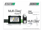
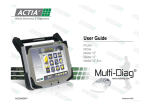
User
Guide
since SW version – 10.1
Last update: January 29, 2010, The right is reserved to change the Manual
1
CONTENTS
I. Communication interface (VCI)
06
Description
Connection
06
07
II. Adapter cables
08
III. Diagnostic stations
12
Multi-Diag Handy
- Technical characteristics
- Buttons and indicator lights
- Power management, configuration and alarm
for low battery – default settings
- Port identification and battery replacement
12
13
14
15
16
IV. The software
17
Installation
Navigation
Software protection system
Configuration
- VCI
- Technical data
- Diagnostic report
- Internet upgrade
17
19
20
22
22
26
28
31
Diagnostic
- Vehicle selection
- Localisation of the diagnostic socket
- Workshop mode and Expert mode
- Express Diag
- Diagnostic applications
33
33
34
35
36
37
V. Important
Instructions for use
Legal provisions
Recycling
43
43
45
45
2
You have just purchased a Multi-Diag diagnostic tool and we thank you
for your trust.
To help you familiarise yourself quickly and easily with the product, this
user guide introduces you to all the functions of your new equipment…
Just let us walk you through.
Developed by ACTIA, a major player in the field of vehicle diagnostic in
Europe, the Multi-Diag range accompanies you daily through all car
maintenance and repair operations.
•
•
•
•
•
•
Resetting of maintenance indicators
Reading / Deletion of DTC's
Reading of parameters (graphic representation)
Testing of actuators
ECU configuration
Coding (injectors, electronic valves…)
Multi-Diag offers you fully innovative functions, giving you a head start
whenever you are performing maintenance work on a vehicle.
•
•
•
•
A Workshop mode and an Expert mode
An Express Diag function
The diagnostic report
An Interface with the technical databases, etc.
The whole ACTIA expertise in a multi-make diagnostic device.
3
ACTIA: our commitments and guarantees
Over 20 years' partnership with vehicle manufacturers: a unique expertise.
Thanks to their expertise in the electronic architecture of vehicles, ACTIA devised the diagnostic in 1985. Since
then, ACTIA have been the diagnostic partner of major manufacturers, and provide network support throughout
the world. This know-how we have shown in our dealings with manufacturers is a unique guarantee in the world
of multi-make diagnostic, and one of the keys to the success of Multi-Diag. As a result, ACTIA is working at the
very heart of all technological and regulations issues in diagnostic, and can anticipate many developments.
Today, over 20,000 users of the Multi-Diag range benefit from the ACTIA expertise.
In the field, to help you build the workshop of the future
With the takeover in 2003 of MULLER BEM – a benchmark in garage equipment and technical inspection – the
ACTIA group offers to their customer a package deal in garage equipment – wheel check, anti-pollution devices,
test benches, vehicle lifts… Moreover, their in-depth knowledge of the garage environment enables ACTIA to
develop diagnostic tools which are perfectly suited to requirements in the field: performance, ergonomics,
mobility, communication… while anticipating the garage of the future.
Multi-Diag equipment and services: the ACTIA trademark quality
With Multi-Diag, you benefit from the same quality of service as manufacturers' after-sales networks throughout
the world: regular upgrades, assistance, training and support…
All ACTIA devices are developed in the group's design offices and manufactured in the group's factories, which
are international benchmarks in the area of PCB production and assembly of complex systems for the automotive
and aeronautics sector.
4
THE MULTI-DIAG RANGE
Diagnostic stations
Further details on page 12
Multi-Diag Handy
Vehicle Communication Interface (VCI)
Further details on page 06
VCI 1 wire
VCI 2 wire
or
VCI 2 Bluetooth
or
Software
Further details on page 17
Multi-Diag software suite including the various
diagnostic applications.
5
I - COMMUNICATION INTERFACE (VCI)
Description
This interface between the diagnostic tool and the vehicle being examined is used for communication with on-board systems.
It is connected:
•
•
to the vehicle via a vehicle diagnostic cable
to the tool via the communication interface in wire mode (USB or RS232 port) or in Bluetooth mode.
VCI 1 - With wire
• 1 VCI unit with wire connection
via USB or RS232 cable
• 1 diagnostic cable for connection to
the vehicle
Compliant with standard SAE J2534 -1, -2
(Pass-thru) and therefore meeting
EURO 5 requirements
VCI 2 - Bluetooth
• 1 VCI unit with wireless connection (Bluetooth)
• 1 cable for connection in wire mode
to the USB port
Compliant with standard SAE J2534 -1, -2
(Pass-thru) and therefore meeting
EURO 5 requirements
VCI 2 - With wire
• 1 VCI unit with wire connection
via USB or RS232 cable
• 1 diagnostic cable for connection
to the vehicle
Compliant with standard SAE J2534 -1, -2
(Pass-thru) and therefore meeting
EURO 5 requirements
6
Connection
Step 1
• Connect the OBD cable to the VCI
(25-pin connector).
Step 2
• Locate the diagnostic plug on your vehicle. Refer to
page 34
in this guide.
• Connect the diagnostic cable to the vehicle. If an
adapter is required, refer to page 8.
Step 3
• Connect the VCI to your diagnostic station:
• VCI with wire: directly connect the port cable of
your tool.
• VCI Bluetooth: follow the Bluetooth connection
procedure described on page 24.
7
II - ADAPTER CABLES
In order to ensure compatibility with the greatest possible number of manufacturers, we offer a full range of cables, available from our
commercial network.
OBD
AT530 4010 or
AT530 4025
Ref. AC911776
BMW
AT107 4083 or
AT107 4094
Ref. AC911801
FIAT – AUTOBIANCHI
ALFA ROMEO – LANCIA
AT1073018
Ref. AC911786
8
LADA
AT107 4043
Ref. AC911785
MERCEDES
AT107 4084
Ref. AC911850
AT107 4085
Ref. AC911851
OPEL
AT107 4047
Ref. AC911782
9
VOLKSWAGEN
SKODA – SEAT - AUDI
AT107 4049
Ref. AC911779
AT107 4033
Ref. AC911777
AT107 4084
Ref. AC911850
FORD
AT107 4090
Ref. AC911708
PEUGEOT - CITROËN
AT107 4051
Ref. AC911781
10
RENAULT
AT107 4046
Ref. AC911780
Universal Connection Parts
AT1073086
Ref. AC911778
Universal Connection Parts
OBD1 n/A
AT1073086
Ref. AC911907
The OBD 1n/A cable is used to perform common
operations on the following systems:
•
•
•
•
•
Ford MS CAN
Peugeot / Citroën CAN
Land Rover, suspension functions
Opel: MS CAN
Fiat: LS CAN (Grande Punto)
11
III - DIAGNOSTIC STATIONS
Multi-Diag Handy
Multi-Diag Handy is a compact device for complex electronic control units diagnostics and implements diagnostics of older vehicles, EOBD
equipped vehicles and complies to Pass-Thru standard (next step in vehicle diagnostics globalisation).
Multi-Diag Handy is a heart of modular system, which can be enhanced by electrical measurement module (Multi-Diag Handy Plus).
Multi-Diag Handy
Multi-Diag Handy Plus
12
Multi-Diag Handy
Ergonomic design with emphasis on garage environment. Touch screen allowing mouse functions.
Technical characteristics
Screen
Touch colour 8.4’’ SVGA 800x600
Processor
Via EdenTM ESP 1 Ghz
Random Access Memory
512 Mb RAM
Hard disk
40 Gb
Drive
External DVD drive to be connected to a USB port
Platform
Windows Embeded
Network and wireless connection
thernet LAN 10/100, Wifi a Bluetooth, IrDA, Modem – 56 kbps
A stylus pen is used to activate the touch screen display and functions in the same way as an external mouse.
Only use the tip of the stylus pen when interacting with the LCD display to prevent damage to the display surface
13
Buttons and indicator lights
A
B
Hard disk
Battery *)
Orange
Flasher light
Hard disk access in progress
OFF
Battery over 90% charged or
operating on battery.
ON
C
Power supply
A
Battery on charge
Green
Charging may not
necessarily start if the
remaining charge in the
battery is greater than 90%.
OFF
The tablet is OFF.
ON
The tablet is ON.
B
C
Blue
Note *): Power management, configuration and alarm for low battery (see next page)
1
1
Brightness adjustment
2
ON/OFF button
3
Command Buttons (not used)
14
Power management, configuration and alarm for low battery – default settings
Classical signalling ( icon
of battery level for MS Windows is placed in notification area) is in Multi-Diag Handy prohibited
(Start \ Control panels \ Performance and Maintenance \ Power Options - valid for Windows XP)
Variations of low battery reporting: Battery = 23% (Displayed message on the need to recharge battery), Battery = 9% (Stand By mode)
Note 1: If Multi-Diag Handy is not used for more than 14 days, battery may be discharged (is recommended to dismount the battery from PC)
Note 2: Is recommended charge battery with power supply adaptor (charging through OBD connector is taken more as an operating voltage)
Variants charging and time-consuming
a)
Power supply adaptor
Charging time
4 to 5 hours
Multi-Diag Handy
OBD adaptor
b)
Power supply adaptor
Charging time
6 to 7 time
Multi-Diag Handy
OBD adaptor
c)
Power supply adaptor
Signalling of battery status is controlled
by LED and pop-up window by Multi-Diag
Handy
d)
Charging time
6 to 7 hours
Multi-Diag Handy
OBD adaptor
Charging time
At least 10 hours
15
Port identification and battery replacement
Ports
1
USB
2
USB
3
DC Power Supply
4
VGA Monitor Outlet
5
Modem (RJ11)
6
Network/Ethernet (RJ45)
7
PCMCIA
Battery replacement
• The tablet must be OFF.
• Slide the battery lock on the rear panel
and pull the battery downwards.
• Insert the battery by sliding it into its housing.
16
IV. Multi-Diag SOFTWARE
Installation
1
2
Read the license contract displayed on the screen. Select
"I accept the terms of the license contract".
Click on the "Next" button.
Insert the Multi-Diag DVD in your drive
to launch the installation of the Multi-Diag software.
4
3
Select the installation language of your choice.
Click on the "Next" button.
Validate the type of installation selected.
17
5
6
Enter your profile name.
If you do not have a specific profile, use the default one: "ACTIA".
Click on the "Next" button.
The installation starts up.
Wait while the data are being downloaded.
7
Once the installation is completed,
click on the "Close" button to close the wizard.
Double-click on the icon located on the desktop
to launch the Multi-Diag software.
18
Navigation
Navigation toolbar
Keyboard button
Displays the digital keyboard
Documentation button
Quick access to the user guide, as well as to previous Multi-Diag News
and other resources.
Configuration button
Access the menu used to change the parameters
and settings of your Multi-Diag.
Internet upgrade button
Upgrade your tool using the Internet.
Diagnostic report button
View your latest diagnostic reports, as well as those
you have archived.
Exit button
Exit the Multi-Diag application.
Other buttons for you to discover along the diagnostic process
Validate button
Validate your choice or select a function.
Tip
The navigation toolbar is displayed on all screens in the
software, do not hesitate to refer to it.
Cancel button
Answer a question in the negative and/or cancel
an action in progress.
Back button
Go back.
19
Software protection system
Multi-Diag 9.2 version introduces a new software protection system. The activation password can be requested after Multi-Diag launch or during of
Multi-Diag work depending on your license. The activation password shouldn’t be requested in case of version upgrade.
1
MULTI-DIAG AUTHENTICATION / TRIAL VERSION
This screen is shown in case of:
• installation on a computer where Multi-Diag has never been installed
• change of computer or computer reinstallation
By pressing
button a screen for an activation password entering will be shown (see
point 2).
By pressing
button an authentication will be cancelled and application will be
switched to 5 days trial period.
2
MULTI-DIAG AUTHENTICATION / ACTIVATION PASSWORD
This screen follows pressing of
button in a previous step – see point 2.
By entering an activation password to an edit box (see mark 1) and pressing
button, the application works without time restrictions.
By pressing
button the authentication will be cancelled and the application will be closed!
1
Note:
You can press
button to show a software keyboard in case of a standard keyboard is not
present.
20
Software protection system
Multi-Diag 9.2 version introduces a new software protection system. The activation password can be requested after Multi-Diag launch or during of
Multi-Diag work depending on your license. The activation password shouldn’t be requested in case of version upgrade.
3
MULTI-DIAG AUTHENTICATION / HW CHANGE
This screen is shown in case of:
• replacing of VCI (malfunction, damage)
• license expiration
To obtain an activation password (see mark 2), please, contact your supplier and give him a
computer code (see mark 1).
Important information:
The activation password is valid for a computer and a VCI where the computer code was
shown.
1
2
By entering the activation password to an edit box (see mark 2), the application will start to work
properly.
By pressing
button an authentication process will be cancelled and an application will
not start a diagnostic
21
Configuration
VCI
The VCI configuration step is essential to the operation of your diagnostic tool.
You must therefore remember to configure your VCI before using it for the 1st time.
Tip
Remember to reconfigure your VCI if you replace it.
1
2
Click on the "Configuration"
button in the navigation toolbar.
The "Application configuration" screen is displayed.
Select "Multi-Diag Configuration".
22
3
4
Enter your VCI number
You will find the VCI serial number to be entered
at the back of the VCI (6 digits).
23
How to configure a Bluetooth VCI
You must configure the Bluetooth link between the VCI and your diagnostic station in order to benefit from the wireless connection possibilities
offered by the tool.
1st step
Check that your diagnostic station has a Bluetooth-type wireless connection.
If such is not the case, you can use a Bluetooth antenna connected to a USB port.
During the connection, your diagnostic station automatically recognises the Bluetooth device.
2nd step
Connect the VCI to the vehicle by using the OBD cable. The VCI is now powered up.
3rd step
Launch the configuration application to configure the Bluetooth link between your diagnostic station and the VCI. Follow the steps below.
2
1
Click on the "Configuration"
button in the navigation toolbar.
The "Application configuration" screen is displayed.
Select "Bluetooth configuration".
24
3
4
To continue with the configuration,
you must connect the VCI in USB wire mode.
Wait while the configuration application is being launched.
5
6
Connect the VCI to your diagnostic station using the USB cable provided.
The VCI has been configured.
Click on the "Exit" button to exit the application.
25
Technical data
The Multi-Diag software allows you to create a link between your technical documentation
(which includes a set of data for vehicle maintenance and repair) and your electronic diagnostic tool.
How to configure your technical documentation software
1
2
Install your technical documentation software
(Autodata or VIVID, not included).
3
Click on the "Configuration"
button in the navigation toolbar.
4
The "Application configuration" screen is displayed.
Select "Technical documentation configuration".
Select the technical documentation database
already incorporated into your tool (AutoData, Vivid).
Then click on the "Validate" button.
Your documentation interface has been installed.
26
How to look up the technical documentation database
In the course of a diagnostic, you will be offered a direct link to the data required for the diagnostic in progress.
1
2
Once the function has been chosen, select the "Technical data" tab.
Click on the technical documentation you wish to look up.
The selected electronic technical documentation
is immediately opened at the relevant chapter.
You will also find in the "Technical data" tab links to a set of technical data (provided by ACTIA) associated with the diagnostic in progress.
In the example above (Renault Mégane II), you have access to the configuration procedure for electro-pneumatic valves.
27
Diagnostic reports
A diagnostic report includes all the data recorded during a diagnostic.
The Multi-Diag software gives you the possibility of archiving these data and of looking them up at a later stage.
How to configure your diagnostic report
You can customise the diagnostic report by adding personal data.
1
2
Click on the "Configuration"
button in the navigation toolbar.
The "Application configuration" screen is displayed.
Select "Multi-Diag Report Configuration".
3
Tip
Add value to your service by customising the diagnostic report.
Enter the information to be included in the report.
28
How to manage diagnostic reports
All diagnostics are stored in a "Diagnostic report" database. You can manage them according to your requirements.
1
2
Click on the "Diagnostic report"
button in the navigation toolbar.
Select a diagnostic report in the list.
Double-click to access the detailed report.
Archive the report selected
Look up the archives
Permanently delete a report
29
You can print your report to keep a written record. You can also, at any time, provide your customer with this document,
which lists all the tests performed in the course of the diagnostic.
3
4
Print your report.
You can either save it or delete it.
Example of printout of a customised diagnostic report.
Display the digital keyboard to enter customer-related information
Permanently delete a report
Print a report
Save a report
Exit the Multi-Diag application
30
Internet upgrade
You can upgrade your tool via the Internet. To do this, you must have an Internet connection.
2
1
Click on the "Internet upgrade"
button in the navigation toolbar.
3
Click on the "Validate" button to continue.
4
Wait while connection to the upgrade server is being established.
Click on the "Validate" button in the bottom right-hand corner
to launch the Multi-Diag Update interface.
31
5
6
Select the upgrade you wish to install.
Wait while the data are being downloaded.
7
The download is completed.
Restart the Multi-Diag software in order to be able to use the new functions.
32
Diagnostic
Vehicle selection
The 1st step in the diagnostic consists in selecting the vehicle. You have a choice between three possibilities:
Entering the VIN identifier
1
Automatic selection
1
Enter the vehicle VIN identifier.
Then click on the "Validate" button.
Manual selection
1
Click on the "Automatic
vehicle selection" button on the home screen.
2
Select the make of the vehicle.
2
Wait while the connection is being established.
Select the vehicle model.
3
Proceed with your diagnostic.
33
Localisation of the diagnostic socket
Once the vehicle has been selected, connect your tool to the diagnostic socket of your vehicle.
Multi-Diag proposes diagrams, photos and videos to help you locate the vehicle diagnostic socket.
2
1
Click on the Localisation icon.
Video
View the location of the diagnostic socket using the diagrams,
photos and videos available in the tool.
34
Workshop mode and Expert mode
Workshop mode
Expert mode
For quick repair or maintenance.
Direct access to the diagnostic applications classified according to activity
(8 activity icons)
Tip
Activity in colour: available
on this vehicle
For a more in-depth repair or diagnostic.
Access to advanced functions, ECU by ECU
Workshop mode
Maintenance:
Maintenance indicator reset, reading/deletion
of defaults, Express Diag, etc.
Wheels and suspension:
Configuration of tyre size, work
on electronic shock absorbers, configuration of electronic
valves (DSG, SSP, etc.), calibration of the steering wheel
angle sensor
Maintenance
Wheels and
suspension
Braking
Air conditioning:
Diagnostic of automatic air-conditioning
systems, additional heating
Air conditioning
Body
and windshield
Equipment
Anti-pollution and exhaust system:
Maintenance and replacement of the particle
filter, lambda sensor, OBD test, anti-pollution
diagnostic.
Braking:
Diagnostic of ABS/ESP ECU's,
locking/unlocking of electric brakes, purging
of brake system, initialisation of slope sensor,
etc.
Equipment:
Installation of after-sales products, alarm,
radio, CD pack, coupling system, etc.
Expert mode:
Access to advanced functions, ECU by ECU
Anti-pollution
and exhaust system
Body and windshield:
Airbag locking/unlocking, reverse radar, xenon
headlights, rain sensor, airbag ECU
Shaded activity:
not available on this vehicle
Engine
Expert mode
Engine:
Injection ECU, injector programming, automatic gearbox, EGR
valve, etc.
Expert mode
35
Express Diag
The Express Diag function allows you to perform a quick diagnostic over the whole vehicle.
With just one click, you can view all the DTC's for all ECU's in the vehicle.
An overview of the general electronic status of the vehicle is displayed on a single screen.
At the same time, the tool automatically generates a diagnostic report summarising the results of this test. You can print this report at any time, so as to keep a hard copy for archiving, or to have a
supporting document to give to your customer.
2
1
Click on the "Express Diag” icon.
Please wait while the tool scans all the ECU's.
3
4
Select the ECU of your choice.
Click on the "Validate” button.
A description of the defaults is displayed in a window.
Select them if necessary.
Use the "Eraser" tool in the navigation toolbar to erase them.
Express Diag in Expert mode
Read all DTC's on all ECU's in the vehicle.
Directly access all ECU functions (identification, reading and deletion of the default memory, reading of parameters, actuator testing, configuration,
etc.).
36
Diagnostic applications
Below are a few examples of the applications most frequently used when selecting an ECU:
Identification
Reading of the default memory
Viewing the defaults present or
stored on the ECU.
Default present = Permanent default
Stored default = Intermittent default.
Obtaining information
on the ECU:
Product reference /
Supplier's name /
Software version / VIN code / etc.
Erasing DTC's
for more information, see p.38
Parameters
Delete all defaults present on the
ECU.
View all parameters managed by the
ECU.
for more information, see p.38
for more information, see p.39
Actuators
Configuration
Activate the actuators managed by
the ECU.
Configure elements managed by the
ECU.
for more information, see p.41
for more information, see p.42
37
Reading of the default memory
You can view the DTC's present or stored on the ECU by using the "Read the
default memory” function.
1
Erasing DTC's
You can immediately delete the DTC's present by using the "Erase DTC's”
function.
1
Select the ECU
of your choice.
Select the ECU of your choice.
2
2
Double-click on
"Read the default memory"
to view the defaults.
3
A new window is displayed,
showing the DTC,
the associated meaning, and the
default status (present or stored).
Select the default to be deleted.
Erase it by using the "Eraser" tool
in the navigation toolbar.
Double-click on
"Erase defaults".
3
Click on the
"Validation" key in the
bottom right-hand corner to
confirm your choice. The
failure memory is then erased.
38
Parameters
You can view the data generated by all the sensors and processed by the ECU being questioned.
1
2
Once the ECU has been selected, the "Parameter" menu is displayed.
Select the group of parameters you wish to view.
3
This icon means that reference data are
available
at the bottom of the page.
These data will help you understand the
information displayed.
The list of parameters is displayed.
The value measured in real time by the ECU is specified for each parameter.
39
Graphic viewing of parameter data
Using this function, which is accessible from the "Parameters” menu, you can view the changes in value of the parameter in graphic mode along a time axis.
1
2
Click on the "Graphics" button in the navigation toolbar.
Select the parameters to be monitored (4 maximum).
3
View the changes to your parameters over time (horizontal axis) and to the values of the
parameter being monitored (vertical axis).
40
Actuators
This application enables you to test all the actuators managed by the ECU being questioned.
2
1
In the list, select the actuator you wish to test.
Select "Actuators".
3
4
Follow the instructions to perform the diagnostic.
The diagnostic is launched.
41
Configuration
This application enables you to configure the ECU's.
The example below provides an illustration of a change in tyre dimensions, requiring modification to the configuration of the ABS ECU.
2
1
Make your selection and click on the
"Validate” button.
Select the ECU (ABS), and then
"Tire size".
3
4
Make your selection and click on the "Validate” button.
Your selection is displayed. Click on the "Confirmation" button to confirm.
5
The change in configuration is confirmed in a window. Click on the 'Validate” button.
42
V. IMPORTANT
Instructions for use
Preliminary remarks
-
This tablet is for professional use only.
The tablet must be used in compliance with ACTIA instructions.
Power supply voltage 8 V to 16 V.
A supply voltage outside these limits may damage the tablet.
Environment
-
Use the tablet at an ambient temperature of 0°C to 45°C for the Multi-Diag Master, and between 0°C to 35°C for the Multi-Diag Mobile.
Protect the tablet from prolonged exposure to sunlight.
Do not place the tablet near sources of flammable liquids to prevent any risks of explosion and fire.
Do not use the tablet in the rain or on damp surfaces to prevent any risk of electric shock or damage to the tablet.
Do not splash the tablet with liquids (water, acid, cleaning fluids, etc.).
Do not leave the cables or peripherals near a source of heat or hot materials.
Handling
-
Do not drop the tablet.
Do not use peripherals (e.g. cables) other than those supplied by ACTIA.
Do not install any software package other than those recommended by ACTIA.
Avoid using the tablet for very long periods (several hours), since some parts of the tablet (I/O connector) may become very hot.
Handling the tablet by the plastic parts to avoid burns.
Do not allow the cables to run over the corner of tables, workbenches or shelves.
Only use the stylus provided, in order to prevent damage to the touch-sensitive screen.
Do not force the CD-ROM drive open (class 1 laser item), this could cause physical damages.
Do not pull on the mains cable when unplugging the tablet from the power supply. Grip the connector when performing this operation.
On road tests, secure the tablet using the vehicle's seat belts.
The road test must not be conducted by the driver. Only a passenger must carry out the test.
Do not place the tablet on an Airbag stowage location. The Airbag may be triggered.
43
Maintenance
In case of damages
- Do not use the tablet.
- Contact your retailer's After-Sales service.
- If the screen glass is broken, do not inhale, touch or ingest liquid crystals.
Glass splinters
Cleaning
-
For external cleaning of the tablet, use a soft cloth impregnated with an suitable cleaning agent (cleaning agent for computer screen).
Do not use solvents
Batteries
Safety precautions
- Do not cause any short-circuits between the 3 battery terminals.
- Do not use the battery for any other applications (emission of a toxic substance and deterioration of the battery).
- Keep the battery away from any flammable sources.
- If the battery life drops, change the battery.
- Always replace the battery with a battery of the same type.
- Do not reverse the polarity of the battery.
Charging the battery
The battery must be charged using the mains adapter only. Do not use a standard charger.
Charge conditions: temperature between 10°C and 40°C for Multi-Diag Master, and between 10°C and 35°C for Multi-Diag Mobile.
The battery must be charged if:
- You have changed the battery and it is not charged.
- The charge indicator shows an insufficient autonomy (see chapter: Diagnostic stations).
To optimise battery performance, we recommend that you charge the battery to 100% (no partial charge) and
only charge the battery when it is completely discharged.
44
Legal provisions
This tool is intended for informed professionals, who as such have, on the one hand, made their own decision to purchase, with no IT consulting service to be provided by
ACTIA, who have no obligation towards them in this respect, and who on the other hand, accept the software and associated user guide as it is, without redress against
ACTIA, either due to an apparent or hidden default, or to the decisions taken by the users based on its consequences, which come under their own competence and
professional care, or to direct or consequential damages which may result from its use and operation.
Copyright 2001 ACTIA® Company.
The information in this document is protected by copyright law. All rights reserved. Reproduction, adaptation or translation without prior approval in writing are prohibited,
except as provided for in copyright law.
The information in this document is liable to change.
The photographs and illustrations in these pages are not contractual.
Recycling
The packaging materials for this product are recyclable and can be reused.
All materials must be disposed of in accordance with local recycling rules.
When disposing of this device, be sure to comply with the law or local regulations.
Batteries must never be thrown away or incinerated, but disposed of in accordance with local regulations
concerning chemical waste.
This product and the accessories packaged with it comply with the EEE directive, except for the batteries.
45