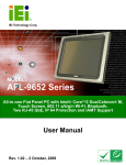
1
AFOLUX CX Series Flat Panel PC AFOLUX CX Series Flat Panel PC Page i AFOLUX CX Series Flat Panel PC Revision MODEL AFOLUX CX Series Flat Panel PC User Manual Revision Number Description Date of Issue 1.00 Initial release July 2007 Page ii AFOLUX CX Series Flat Panel PC Copyright COPYRIGHT NOTICE The information in this document is subject to change without prior notice in order to improve reliability, design and function and does not represent a commitment on the part of the manufacturer. In no event will the manufacturer be liable for direct, indirect, special, incidental, or consequential damages arising out of the use or inability to use the product or documentation, even if advised of the possibility of such damages. This document contains proprietary information protected by copyright. All rights are reserved. No part of this manual may be reproduced by any mechanical, electronic, or other means in any form without prior written permission of the manufacturer. TRADEMARKS IBM PC is a registered trademark of International Business Machines Corporation. INTEL is a registered trademark of INTEL Corporation. Other product names mentioned herein are used for identification purposes only and may be trademarks and/or registered trademarks of their respective owners. Page iii AFOLUX CX Series Flat Panel PC Packing List NOTE: If any of the components listed in the checklist below are missing, please do not proceed with the installation. Contact the IEI reseller or vendor you purchased the AFOLUX CX series from or contact an IEI sales representative directly. To contact an IEI sales representative, please send an email to [email protected]. The items listed below should all be included in the AFOLUX CX series package. 1 x AFOLUX CX series panel PC 1 x Power cord 1 x 80W power adapter 1 x HDD cable 1 x eSATA cable 1 x Screw set 1 x Touch pen 1 x User Manual and driver CD 1 x Wall mounting kit (optional) 1 x Arm mounting kit (optional) 1 x Stand mounting kit (optional) 1 x 128MB CompactFlash® card with Windows CE 5.0 pre-installed (optional) 1 x 1GB CompactFlash® card with Windows XPE pre-installed (optional) Images of the above items are shown in Chapter 3. Page iv AFOLUX CX Series Flat Panel PC Precautions SAFETY PRECAUTIONS 1. Prior to installing, moving, and modifying the panel PC, make sure that the unit’s power is turned off and the power cord is disconnected. 2. Do not apply voltage levels that exceed the specified voltage range. Doing so may cause fire or an electrical shock. 3. Electric shock can occur if the panel is opened. Do not drop or insert any objects into the ventilation openings of the panel PC. 4. Only qualified engineers from certified system integrators or VARs are allowed to make necessary functional modifications to the panel PC, e.g., adding a touch screen. IEI offers the customization service on a pre-order basis. 5. If considerable amount of dust, water, or fluids entered the panel PC, turn off the power supply immediately, unplug the power cord, and contact the vendor. 6. Explosions may occur with installations in environments where flammable gases are present. 7. Fault-tolerant and failsafe designs should be implemented with the use of the series models on transportation vehicles, ships, safety/security devices, or medical devices not related to life-support functionalities. Users/integrators should take the responsibility for implementations with adequate levels of reliability and safety. 8. Preventive designs should be implemented so as to avoid the communications faults between the panel PC and the PC/workstation/terminals that controls it. 0. HANDLING PRECAUTIONS 1. Do not drop the panel PC against a hard surface. Doing so may damage the display. 2. Do not strike or exert excessive force onto the touch panel. 3. Touching the touch panel using a sharp object may damage the LCD panel. 4. Avoid environments exposed to direct sunlight, dust, or chemical vapors. 5. The panel PC is actively cooled. In no circumstances should the panel PC Page v AFOLUX CX Series Flat Panel PC operate with the openings obstructed by foreign objects. However, the ambient temperature of the installation site should be observed and controlled to avoid overheating the panel PC. 6. Condensation might form inside the panel PC chassis if exposed to sudden changes in temperature. 7. Carefully route the power cord so that people cannot step on it. Do not place anything over the power cord. 8. If the equipment should be left unused for an extended period of time, disconnect it from the power source to avoid damage by transient over-voltage. 9. If any of the following situations arises, get the equipment checked by service personnel: 0. o o o o The power cord or plug is damaged. Liquid has penetrated into the equipment. The equipment has been exposed to moisture. The equipment does not work properly, or the user cannot get it to work according to the user manual. o o The equipment has been dropped and damaged. The equipment shows obvious signs of breakage. WARNING! Any changes or modifications made to the equipment that are not expressly approved by the relevant standards could void the authority to operate the equipment. MAINTENANCE AND CLEANING Note the following precautions before beginning to clean the Panel PC. When cleaning any single part or component of the computer, please read and understand the details below fully. Except for the properly installed front LCD panel, never spray or squirt liquids directly onto any computer component. To clean the device, please rub it with Page vi AFOLUX CX Series Flat Panel PC a piece of dry and soft cloth or a slightly moistened cloth with the exterior casing. The interior of the Panel PC does not require cleaning. Keep fluids away from the Panel PC and the interior of it. Be cautious of the tiny removable components when using a vacuum cleaner to absorb the dirt on the floor. Turn the system off before cleaning up the Panel PC. Never drop any tiny objects through the openings of the Panel PC or get circuit board damp or wet. Be cautious of all kinds of cleaning solvents or chemicals when using it for the sake of cleaning. Some individuals may be allergic to the ingredients. Avoid any food, drink or cigarette around the Panel PC. CLEANING TOOLS Although many companies have created products to help improve the process of cleaning the computer and peripherals, users can also use household items to clean their computers and peripherals. Below is a list of items to use while cleaning the computer or computer peripherals. Please keep in mind that some components in the computer may only be cleaned using a product designed for cleaning that component, if this is the case it will be mentioned in the cleaning tips. Cloth - A piece of cloth is the best tool to use when rubbing up a component. Although paper towels or tissues can be used on most hardware as well, it is recommended to rub it with a piece of cloth. Water or rubbing alcohol – Moisten a piece of cloth a bit with some water or rubbing alcohol and rub it on the computer. Unknown solvents may be harmful to the plastics parts. Vacuum cleaner - Absorb the dust, dirt, hair, cigarette particles, and other particles out of a computer can be one of the best methods of cleaning a computer. Over time these items can restrict the airflow in a computer and cause circuitry to corrode. Cotton swabs - Cotton swabs moistened with rubbing alcohol or water are Page vii AFOLUX CX Series Flat Panel PC excellent tools for wiping hard to reach areas in the keyboard, mouse, and other locations. Foam swabs - Whenever possible it is better to use lint free swabs such as foam swabs. ESD PRECAUTIONS Observe all conventional anti-ESD methods while handling the components contained within the LCD should the need arise for adding a functionality. The use of a grounded wrist strap and an anti-static work pad is recommended. Avoid dust and debris or other static-accumulating materials in the work area. Page viii AFOLUX CX Series Flat Panel PC Table of Contents 1 INTRODUCTION................................................................................................... 17 1.1 AFOLUX CX SERIES FLAT PANEL PC OVERVIEW .................................................. 18 1.1.1 Model Variations .............................................................................................. 18 1.1.2 Applications ..................................................................................................... 18 1.1.3 Standard Features ............................................................................................ 19 1.2 EXTERNAL OVERVIEW ............................................................................................. 20 1.2.1 General Description......................................................................................... 20 1.2.2 Front Panel ...................................................................................................... 20 1.2.3 Rear Panel ....................................................................................................... 20 1.2.4 Bottom Panel.................................................................................................... 21 1.3 INTERNAL OVERVIEW............................................................................................... 22 1.4 SPECIFICATIONS ....................................................................................................... 23 1.4.1 Preinstalled Hardware Components ................................................................ 23 1.4.2 System Specifications ....................................................................................... 24 1.4.3 Motherboard Specifications ............................................................................. 26 1.4.4 Flat Panel Screen Specifications ..................................................................... 27 1.4.5 Touch Screen Specifications............................................................................. 28 1.4.6 Bluetooth Module Specifications ..................................................................... 29 1.4.7 Optional GPRS Module Specifications............................................................ 30 1.5 DIMENSIONS ............................................................................................................ 31 1.5.1 AFL-15A-CX Dimensions ................................................................................ 31 1.5.2 AFL-17A-CX Dimensions ................................................................................ 32 1.5.3 AFL-19A-CX Dimensions ................................................................................ 33 2 MOTHERBOARD.................................................................................................. 35 2.1 INTRODUCTION ........................................................................................................ 36 2.2 CPU SUPPORT.......................................................................................................... 36 2.2.1 VIA C7® Specifications .................................................................................... 36 2.3 SYSTEM CHIPSET ..................................................................................................... 37 2.4 GRAPHICS SUPPORT ................................................................................................. 37 2.5 ETHERNET CONTROLLER SPECIFICATIONS ............................................................... 38 Page ix AFOLUX CX Series Flat Panel PC 2.5.1 Overview .......................................................................................................... 38 2.5.2 Features ........................................................................................................... 38 2.6 PERIPHERAL DEVICE INTERFACES, CONNECTORS, AND SLOTS ................................. 39 2.6.1 OEM Options ................................................................................................... 39 2.6.2 Internal Slots.................................................................................................... 39 2.6.3 Internal Peripheral Device Connectors........................................................... 39 2.6.4 External Peripheral Device Connectors.......................................................... 40 3 INSTALLATION .................................................................................................... 41 3.1 INSTALLATION PRECAUTIONS ................................................................................... 42 3.2 PREINSTALLED COMPONENTS .................................................................................. 42 3.3 INSTALLATION AND CONFIGURATION STEPS ............................................................. 43 3.4 UNPACKING.............................................................................................................. 43 3.4.1 Packing List ..................................................................................................... 44 3.5 CF CARD INSTALLATION .......................................................................................... 45 3.6 HDD INSTALLATION ................................................................................................ 47 3.7 MOUNTING THE SYSTEM .......................................................................................... 50 3.7.1 Wall Mounting.................................................................................................. 51 3.7.2 Arm Mounting .................................................................................................. 53 3.8 BOTTOM PANEL CONNECTORS ................................................................................. 55 3.8.1 LAN Connection............................................................................................... 55 3.8.2 Serial Device Connection ................................................................................ 56 3.8.3 USB Device Connection................................................................................... 57 4 SYSTEM MAINTENANCE .................................................................................. 59 4.1 SYSTEM MAINTENANCE INTRODUCTION .................................................................. 60 4.2 MOTHERBOARD REPLACEMENT ............................................................................... 60 4.3 INTERNAL ALUMINUM COVER REMOVAL ................................................................. 60 4.4 MEMORY MODULE REPLACEMENT .......................................................................... 63 4.5 JUMPER SETTINGS .................................................................................................... 64 4.5.1 J4: LCD Voltage Select Jumper Settings.......................................................... 65 4.5.2 JP7: COM2 Mode Select Jumper Settings....................................................... 66 4.5.3 JP8: COM2 Mode Select Jumper Settings....................................................... 66 5 AMI BIOS SETUP.................................................................................................. 67 5.1 INTRODUCTION ........................................................................................................ 68 Page x AFOLUX CX Series Flat Panel PC 5.1.1 Starting Setup................................................................................................... 68 5.1.2 Using Setup ...................................................................................................... 68 5.1.3 Getting Help..................................................................................................... 69 5.1.4 Unable to Reboot After Configuration Changes.............................................. 69 5.1.5 BIOS Menu Bar................................................................................................ 69 5.2 MAIN ....................................................................................................................... 70 5.3 ADVANCED ............................................................................................................... 71 5.3.1 CPU Configuration.......................................................................................... 72 5.3.2 IDE Configuration ........................................................................................... 73 5.3.2.1 IDE Master, IDE Slave ............................................................................. 75 5.3.3 Super IO Configuration.................................................................................... 80 5.3.4 ACPI Configuration ......................................................................................... 83 5.3.5 APM Configuration.......................................................................................... 84 5.3.6 Remote Access Configuration .......................................................................... 86 5.3.7 USB Configuration........................................................................................... 89 5.3.7.1 USB Mass Storage Device Configuration................................................. 91 5.4 PCI/PNP .................................................................................................................. 94 5.5 BOOT ....................................................................................................................... 97 5.5.1 Boot Settings Configuration............................................................................. 97 5.5.2 Boot Device Priority ...................................................................................... 100 5.5.3 Hard Disk Drives ........................................................................................... 101 5.5.4 Removable Drives .......................................................................................... 102 5.6 SECURITY............................................................................................................... 103 5.7 CHIPSET ................................................................................................................. 105 5.8 EXIT ....................................................................................................................... 107 A INTERFACE CONNECTORS ............................................................................ 109 A.1 PERIPHERAL INTERFACE CONNECTORS ..................................................................110 B BIOS CONFIGURATION OPTIONS .................................................................117 B.1 BIOS CONFIGURATION OPTIONS ............................................................................118 C SOFTWARE DRIVERS ....................................................................................... 123 C.1 REMOTE MANAGEMENT TOOL .............................................................................. 124 C.2 TOUCH PANEL DRIVER .......................................................................................... 124 C.2.1 Introduction ................................................................................................... 124 Page xi AFOLUX CX Series Flat Panel PC C.2.2 Driver Installation......................................................................................... 125 C.2.3 Touch Panel Driver Configuration................................................................ 128 D WATCHDOG TIMER .......................................................................................... 129 E HAZARDOUS MATERIALS DISCLOSURE ................................................... 133 E.1 HAZARDOUS MATERIAL DISCLOSURE TABLE FOR IPB PRODUCTS CERTIFIED AS ROHS COMPLIANT UNDER 2002/95/EC WITHOUT MERCURY ..................................... 134 F INDEX.................................................................................................................... 137 Page xii AFOLUX CX Series Flat Panel PC List of Figures Figure 1-1: Front View.................................................................................................20 Figure 1-2: AFL CX Series Rear View........................................................................21 Figure 1-3: AFOLUX CX Series Bottom View ...........................................................22 Figure 1-4: AFOLUX CX Series Internal Overview ...................................................23 Figure 1-5: AFL-15A-CX Dimensions (units in mm).................................................31 Figure 1-6: AFL-17A-CX Dimensions (units in mm).................................................32 Figure 1-7: AFL-19A-CX Dimensions (units in mm).................................................33 Figure 2-1: AFLMB-CX700 Connector Overview......................................................40 Figure 3-1: AFL-15A-CX Back Cover Retention Screws..........................................46 Figure 3-2: AFL-17A-CX Back Cover Retention Screws..........................................46 Figure 3-3: AFL-19A-CX Back Cover Retention Screws..........................................47 Figure 3-4: CF Card Location.....................................................................................47 Figure 3-5: AFL-15A-CX Aluminum Back Cover Retention Screws.......................48 Figure 3-6: AFL-17A-CX Aluminum Back Cover Retention Screws.......................48 Figure 3-7: AFL-19A-CX Aluminum Back Cover Retention Screws.......................49 Figure 3-8: AFL-19A-CX HDD Bracket Retention Screws .......................................49 Figure 3-9: AFL-CX HDD Retention Screws .............................................................50 Figure 3-10: Wall-mounting Bracket..........................................................................51 Figure 3-11: Chassis Support Screws.......................................................................52 Figure 3-12: Secure the Panel PC..............................................................................53 Figure 3-13: AFL-CX Arm Mounting Retention Screw Holes ..................................54 Figure 3-14: LAN Connection.....................................................................................55 Figure 3-15: Serial Device Connector .......................................................................56 Figure 3-16: USB Device Connection........................................................................57 Figure 4-1: AFL-15A-CX Aluminum Back Cover Retention Screws.......................61 Figure 4-2: AFL-17A-CX Aluminum Back Cover Retention Screws.......................62 Figure 4-3: AFL-19A-CX Aluminum Back Cover Retention Screws.......................62 Figure 4-4: SO-DIMM Socket Location ......................................................................63 Page xiii AFOLUX CX Series Flat Panel PC Figure 4-5: DDR2 SO-DIMM Module Installation ......................................................64 Figure 4-6: Jumper Locations....................................................................................65 Page xiv AFOLUX CX Series Flat Panel PC List of Tables Table 1-1: Model Variations........................................................................................18 Table 1-2: AFOLUX CX Series System Specifications ............................................25 Table 1-3: Motherboard Specifications .....................................................................26 Table 1-4: TFT LCD Monitor Specifications..............................................................27 Table 1-5: Touch Panel Specifications......................................................................28 Table 1-6: Bluetooth Module Specifications ............................................................29 Table 1-7: GPRS Module Specifications ...................................................................30 Table 4-1: LCD Voltage Setup Jumper Settings.......................................................65 Table 4-2: COM2 Mode Select Jumper Settings.......................................................66 Table 4-3: COM2 Mode Select Jumper Settings.......................................................66 Table 5-1: BIOS Navigation Keys...............................................................................69 Page xv AFOLUX CX Series Flat Panel PC THIS PAGE IS INTENTIONALLY LEFT BLANK Page xvi AFOLUX CX Series Flat Panel PC Chapter 1 1 Introduction Page 17 AFOLUX CX Series Flat Panel PC 1.1 AFOLUX CX Series Flat Panel PC Overview The AFOLUX CX series flat panel PC is a flexible, multi-functional flat panel PC that can be applied in diverse operational environments and implemented in multi-faceted applications. The AFOLUX CX series comes fully kitted with a high-performance motherboard and a host of other peripheral interface connectors. The integrated wireless LAN module and Bluetooth module ensure an uninterrupted wireless connection. The AFOLUX CX series is designed for ease of use and easy installation. 1.1.1 Model Variations The models of AFOLUX CX series are listed in Table 1-1. AFL-15A-CX CPU LCD ® -15GZ/WT-R/512MB VIA C7 -05GZ/WT-R/512MB VIA Eden AFL-17A-CX TM ® -05GZ/WT-R/512MB VIA Eden AFL-19A-CX TM Yes Yes 15” 512MB DDR2 Yes Yes -05GZ/WT-R/512MB ® VIA Eden TM Wireless LAN Touch screen 512MB DDR2 Yes Yes 17” 512MB DDR2 Yes Yes LCD VIA C7 Memory 17” CPU -15GZ/WT-R/512MB Touch screen 512MB DDR2 LCD VIA C7 Wireless LAN 15” CPU -15GZ/WT-R/512MB Memory Memory Wireless LAN Touch screen 19” 512MB DDR2 Yes Yes 19” 512MB DDR2 Yes Yes Table 1-1: Model Variations 1.1.2 Applications The AFOLUX CX series all-in-one panel PC is designed for multiple applications. Its durability and strength makes it an ideal choice for public access computers. Some possible applications include: Vehicle Interior device o o Truck PC Logistic car PC General computing Page 18 AFOLUX CX Series Flat Panel PC o o PC based testing center Distance learning Industrial applications o o o o Plant environment monitoring system Factory automation platform Manufacturing shop flow Equipment and device control Home and building automation o o o Digital surveillance system E-home platform Home IA control terminal Self-Service Kiosk o o o Receptionist kiosk in hotel and business premises Self registration terminal in hospital and airport Ticket vending machine for transportation use 1.1.3 Standard Features Some of the standard features of the AFOLUX CX series flat panel PC include: VIA C7® 1.5GHz processor/VIA EdenTM 500MHz processor Rugged mechanism design with ABS/PC case IP 64 dustproof and waterproof front panel One 512MB DDR2 memory module pre-installed Wireless LAN module and Bluetooth module integrated Dual GbE LAN support One CompactFlash® Type II socket support Optional GPRS module Simplified installation process RoHS compliance Page 19 AFOLUX CX Series Flat Panel PC 1.2 External Overview 1.2.1 General Description The AFOLUX CX series is a stylish flat panel PC that comprises of a screen, rear panel, and bottom panel. An ABS/PC plastic front frame surrounds the front screen. The rear panel provides screw holes for a wall-mounting bracket compliant with VESA FDMI standard. The bottom panel provides access to external interface connectors that include LAN, VGA, USB 2.0 ports, serial ports, reset button, power connector and power switch. 1.2.2 Front Panel The front side of the AFOLUX CX series is a flat panel TFT LCD screen surrounded by an ABS/PC plastic frame. Figure 1-1: Front View 1.2.3 Rear Panel The rear panel provides access to retention screw holes that support the wall mounting. Refer to Figure 1-2. Page 20 AFOLUX CX Series Flat Panel PC Figure 1-2: AFL CX Series Rear View 1.2.4 Bottom Panel The bottom panel of the AFOLUX CX series has the following I/O interfaces (Figure 1-3): 4 x USB 2.0 connectors 1 x AC power adapter connector 1 x Power switch 1 x RS-232 serial port connector 1 x RS-232/422/485 serial port connector 2 x RJ-45 GbE connectors 1 x Reset button 1 x VGA connector (AFL-17A-CX/AFL-19A-CX only) Page 21 AFOLUX CX Series Flat Panel PC Figure 1-3: AFOLUX CX Series Bottom View 1.3 Internal Overview The AFOLUX CX series internal components are protected in an aluminum chassis inside the plastic back cover. The motherboard, wireless LAN module, Bluetooth module and DDR2 memory module are installed on a metal sheet that protects the rear of the TFT LCD screen (Figure 1-4). Below the metal sheet is a circuit board that is connected to the screen and the motherboard. Page 22 AFOLUX CX Series Flat Panel PC Figure 1-4: AFOLUX CX Series Internal Overview 1.4 Specifications 1.4.1 Preinstalled Hardware Components The AFOLUX CX series flat panel PC has the following preinstalled components: 1 x Motherboard 1 x TFT LCD screen 1 x Touch screen 1 x Inverter 1 x Wireless LAN module 1 x Bluetooth module 1 x DDR2 memory module The technical specifications for some of these components and the system are shown in the sections below. Page 23 AFOLUX CX Series Flat Panel PC 1.4.2 System Specifications The technical specifications for the AFOLUX CX series systems are listed in Table 1-2. SPECIFICATION AFL-15A-CX AFL-17A-CX AFL-19A-CX Front Panel ABS/PC plastic front panel Chassis Aluminum chassis LCD Panel 15” 17” 19” Resolution 1024 x 768 1280 x 1024 1280 x 1024 Brightness 350 cd/m2 300 cd/m2 300 cd/m2 Contrast Ratio 400:1 800:1 800:1 Viewing Angle (H-V) 120/100 160/160 160/160 Backlight MTBF 50000 50000 50000 Touch Screen 5-wire resistive type (touch controller IC is on-board) SSD CompactFlash® Type II Audio AMP 1.5W + AMP 1.5W (internal speaker) Extension 1 x Mini PCI (for wireless LAN module) 1 x Bluetooth module (USB interface, Bluetooth v2.0) Anti-shock Drive Bay 1 x 2.5” HDD bay 1 x 2.5” HDD bay GPRS Module or Optional optional GPRS Module Page 24 AFOLUX CX Series Flat Panel PC SPECIFICATION I/O AFL-15A-CX AFL-17A-CX AFL-19A-CX 4 x USB 2.0 port 1 x Power switch 1 x eSATA port 1 x RS-232 serial port 1 x RS-232/422/485 serial port 2 x Gigabit Ethernet ports 1 x Reset button 1 x VGA port (AFL-17A-CX/AFL-19A-CX only) 1 x AT/ATX power switch (internal) Power 12V, 80W DC power adapter Power Consumption 52W Mounting Feature Wall, Arm, Stand Operating Temperature 0ºC ~40ºC Storage Temperature -20ºC ~60ºC Relative Humidity 10% ~ 80% RH, non-condensing Vibration 5 - 17Hz, 0.1” double amplitude displacement. 61W 61W 17 - 640Hz, 1.5G acceleration, peak to peak. Shock 10G Acceleration, peak to peak (11ms) Dimension (W x H x D) 394 x 309 x 61 428 x 350 x 65 470 x 383 x 67 Net/Gross Weight 3.2Kg 5Kg 5.6Kg Front Panel Protection IP 64 compliant Safety & EMI CE / FCC / EMC / CB Table 1-2: AFOLUX CX Series System Specifications Page 25 AFOLUX CX Series Flat Panel PC 1.4.3 Motherboard Specifications The AFOLUX CX series come with an AFLMB-CX700 motherboard. The technical specifications of the motherboard are listed in Table 1-3. Specification AFLMB-CX700 CPU VIA C7® / VIA EdenTM Chipset VIA CX-700M Display CRT integrated in VIA CX-700M Supports panel resolution from VGA to UXGA (1600 x 1200) Supports one Dual-Channel / two Single-Channel LVDS panel Memory Supports one DDR2 400/533 200-pin SO-DIMM SDRAM module up to 1GB Extension One mini PCI slot BIOS Award BIOS SSD CFII Super I/O N/A for legacy free Audio VT1708 (High Definition Audio) LAN 10/100/1000 Base-T dual RTL8110SC COM Two RS-232 serial ports IDE One 44-pin IDE connects to two IDE devices Touch Screen Controller DMC9000 Power Supply 12V ATX power support Dimensions 102mm x 186mm Table 1-3: Motherboard Specifications Page 26 AFOLUX CX Series Flat Panel PC 1.4.4 Flat Panel Screen Specifications The AFOLUX CX series come with a TFT LCD monitor at the front of the flat panel PC (see Figure 1-1). The specifications for the LCD monitor are shown in Table 1-4 below. SPECIFICATION AFL-15A-CX AFL-17A-CX AFL-19A-CX Model AUO-G150XG01 AUO-M170EG01 VD AUO-M190EG02 V4 Size 15” 17” 19” Resolution 1024 x 768 (XGA) 1280 x 1024 (SXGA) 1280 x 1024 (SXGA) Active Area (mm) 304.128 x 228.096 337.920 x 270.336 376.32 x 301.06 Pixel Pitch (mm) 0.297 x 0.297 0.264 x 0.264 0.294 x 0.294 LCD Color Native 262K colors Native 16.7M colors Native 16.7M colors View Angel (H/V) 120/100 160/160 160/160 Brightness (cd/m2) 350 300 300 Contrast Ratio 400:1 800:1 800:1 Response Time (ms) 16 (Tr + Tf) 5 (Tr + Tf) 5 (Tr + Tf) Power Consumption 11.5 25.8 24.71 Input Voltage (V) 3.3 5.0 5.0 Backlight 2 CCFL 2 CCFL 2 CCFL Electrical Interface 1ch LVDS 2ch LVDS 2ch LVDS Backlight MTBF (hrs.) 50000 50000 50000 Outline Dimensions 326.5 x 253.5 x 12.0 358.5 x 296.5 x 15.8 396 x 324 x 16.3 (W) (mm) Table 1-4: TFT LCD Monitor Specifications Page 27 AFOLUX CX Series Flat Panel PC 1.4.5 Touch Screen Specifications The AFOLUX CX series come with an analog resistive type touch panel. Table 1-5 lists the touch panel specifications. SPECIFICATION AFL-15A-CX AFL-17A-CX Model PANJIT 1150508B Type Analog Resistive Type Touch Panel Wire Type 5-wire Viewing Area (mm) 232.1 x 308.2 342.05 x 275.45 306.05 x 381.30 Active Area (mm) 228.1 x 304.1 339.0 x 272.4 301.05 x 376.30 Total Transmission 78% Maximum Voltage DC7V Connector Type FPC. Operating Temperature -10°C ~ 40°C -10°C ~ 40°C -10°C ~ 40°C Operating Humidity 20% ~ 90% RH Storage Temperature -20°C ~ 70°C Storage Humidity 20% ~ 90% RH Dimensions 257.5 x 333.6 x 2.9 365.0 x 295.08 x 2.9 330.0 x 404.6 x 2.8 Table 1-5: Touch Panel Specifications Page 28 PANJIT 1171505A AFL-19A-CX PANJIT 1190503A AFOLUX CX Series Flat Panel PC 1.4.6 Bluetooth Module Specifications The AFOLUX CX series come with a Bluetooth module. The technical specifications of the Bluetooth module are listed in Table 1-6. Specification Bluetooth Module Standard Bluetooth v2.0 Frequency Band 2.402GHz~2.480GHz unlicensed ISM band Modulation Method GFSK for 1Mbps π/4-DQPSK for 2Mbps 8-DPSK for 3Mbps Spread Spectrum FHSS (Frequency Hopping Spread Spectrum) RF Output Power Class 2 (under 4dBm) Antenna Terminal 50 Ohms DC Power DC 3.3V or DC 5V I/O Interface USB 2.0 interface Two GPIO Interface LED link indicator interface Dimensions 35mm x 11mm Operating System Windows XP, Windows 2000, Windows 98SE, Windows Me Table 1-6: Bluetooth Module Specifications Page 29 AFOLUX CX Series Flat Panel PC 1.4.7 Optional GPRS Module Specifications The GPRS module is one of the OEM options for the AFOLUX CX series. The technical specifications of the GPRS module are listed in Table 1-7. Specification GPRS Module EDG/GPRS/GSM Air Interface Quad-band operation GSM850, EGSM 900, DCS 1800, PCS 1900 GSM Power Class 4 (2W) for 850/900 bands GSM Power Class 1 (1W) for 1800/1900 bands EDFE class E2 (+27dBm in 850/900 bands, +26dBm in 1800/1900 bands) GSM/GPRS Rel ’97; PCS 1900 Rel ’98; EGPRS Rel ’99 compliant EGPRS/GPRS (PS) Feature Set GPRS Class 10, coding schemes 1-4 EDGE Class 10, Multi-slot classes 1-9 GPRS/EGPRS Class B type 1 MT Link Adaptation Incremental redundancy (IR) USB Interface USB 2.0 +5VDC SIM Card Interface 3.0V interface Temperature -30°C ~ +65°C Humidity Up to 95%, non-condensing Dimensions 109.3mm x 42.7mm x 17.7mm Operating System Windows 2000/XP Home/XP Professional Table 1-7: GPRS Module Specifications Page 30 AFOLUX CX Series Flat Panel PC 1.5 Dimensions 1.5.1 AFL-15A-CX Dimensions The dimensions of the AFL-15A-CX flat panel PC are shown in Figure 1-5 below. Figure 1-5: AFL-15A-CX Dimensions (units in mm) Page 31 AFOLUX CX Series Flat Panel PC 1.5.2 AFL-17A-CX Dimensions The dimensions of the AFL-17A-CX flat panel PC are shown in Figure 1-6 below. Figure 1-6: AFL-17A-CX Dimensions (units in mm) Page 32 AFOLUX CX Series Flat Panel PC 1.5.3 AFL-19A-CX Dimensions The dimensions of the AFL-19A-CX flat panel PC are shown in Figure 1-7 below. Figure 1-7: AFL-19A-CX Dimensions (units in mm) Page 33 AFOLUX CX Series Flat Panel PC THIS PAGE IS INTENTIONALLY LEFT BLANK Page 34 AFOLUX CX Series Flat Panel PC Chapter 2 2 Motherboard Page 35 AFOLUX CX Series Flat Panel PC 2.1 Introduction The AFOLUX CX series flat screen PC contains the AFLMB-CX700 motherboard. The motherboard is the heart of any computer and is responsible for transmitting, receiving and processing data as well as driving the different onboard devices. This chapter gives a brief introduction to the AFLMB-CX700 motherboard. 2.2 CPU Support The AFLMB-CX700 motherboard comes with a preinstalled VIA C7® or VIA EdenTM CPU. 2.2.1 VIA C7® Specifications The specifications for the VIA C7® and VIA EdenTM processor are listed below CPU clock speeds up to 2.0GHz Full x86 Operating System and software application compatibility VIA V4 Bus up to 800MHz FSB 16 pipeline stages Efficiency enhanced 128KB full-speed exclusive L2 cache with 32-way associativity Sophisticated branch prediction mechanism MMX, SSE, SSE2 & SSE3 instruction sets Full-speed FPU IO/APIC support 90nm SOI (Silicon-on-Insulator) process technology x86 processor die (30mm2) Compact VIA nanoBGA2 package (21mm x 21mm) AES Encryption Secure Hash SHA-1 and SHA-256 Two Quantum-based Random Number Generators NX Execute Protection Page 36 AFOLUX CX Series Flat Panel PC 2.3 System Chipset The AFLMB-CX700 motherboard has a preinstalled VIA CX-700M system chipset. The system chipset features are listed below. 533MB/sec Front Side Bus Supports up to 4GB DDR2 533/400MHz or DDR400/333/266MHz SDRAM Integrated VIA UniChrome Pro Graphics Chromotion™ video engine MPEG-2 Decoder Video De-blocking Adaptive De-Interlace DuoView+™ Optimized Unified memory Architecture (UMA) 200MHz Graphics Engine Clock with separated 128-bit data paths 128-bit 2D and 3D Graphics engine Multi-configuration LVDS/DVI transmitter Support for VIA Vinyl HD Audio Serial ATA support for up to 2 devices Parallel ATA133/100/66 support for up to 2 devices Support for up to 6 USB 2.0 ports 2.4 Graphics Support The VIA CX700M utilizes the VIA UniChrome™ Pro Integrated Graphics Processor (IGP) ensuring optimal performance for all multimedia, entertainment, and productivity applications. The graphics processor features are listed below. With a 200MHz 2D/3D graphics engine 128-bit data paths for pixel data flow Texture/command access Chromotion™ video engine raises the bar for digital entertainment support MPEG-2, MPEG-4 and WMV9 decoding integrated Flawless digital video playback with ultra-low CPU-utilization Adaptive De-Interlacing and Video Deblocking advanced rendering tools Ensure clearer playback of digital content on all display devices Page 37 AFOLUX CX Series Flat Panel PC 2.5 Ethernet Controller Specifications 2.5.1 Overview A highly integrated and cost-effective single-chip, fast RealTek RTL8110SC GbE Ethernet controller is interfaced through first the PCI bus to the CPU and system chipset. The RealTek RTL8110SC controller provides 10Mbps, 100Mbps or 1000Mbps Ethernet connectivity to the AFLMB-CX700. 2.5.2 Features Integrated 10/100/1000 transceiver Auto-Negotiation with Next Page capability Supports PCI rev.2.3, 32-bit, 33/66MHz Supports CLKRUNB and MiniPCI v1.0 Supports pair swap/polarity/skew correction Crossover Detection & Auto-Correction Wake-on-LAN and remote wake-up support Microsoft® NDIS5 Checksum Offload (IP, TCP, UDP) and largesend offload support Supports Full Duplex flow control (IEEE 802.3x) Fully compliant with IEEE 802.3, IEEE 802.3u, IEEE 802.3ab Supports IEEE 802.1P Layer 2 Priority Encoding Supports IEEE 802.1Q VLAN tagging Serial EEPROM 3.3V signaling, 5V PCI I/O tolerant Transmit/Receive FIFO (8K/64K) support Supports power down/link down power saving Supports PCI Message Signaled Interrupt (MSI) Page 38 AFOLUX CX Series Flat Panel PC 2.6 Peripheral Device Interfaces, Connectors, and Slots The peripheral device connectors, interfaces and slots on the AFLMB-CX700 motherboard are listed in the sections below. 2.6.1 OEM Options Many of the peripheral device connectors listed below are not connected to any devices. These connectors are reserved for OEM customizations. For a customized option, please contact the vendor, reseller or IEI sales representative. 2.6.2 Internal Slots The slots listed below can all be found on the AFLMB-CX700 motherboard. 1 x 200-pin DDR2 SO-DIMM socket 1 x CF Type II slot 1 x Mini PCI slot (for wireless LAN module) 2.6.3 Internal Peripheral Device Connectors The peripheral device connectors listed below are located on the AFLMB-CX700 motherboard and used for the AFOLUX series. Figure 2-1 shows the overview of the connectors that are used for the AFOLUX series. 1 x Audio connector 1 x Inverter connector 1 x LCD interface connector 1 x LED connector 1 x Power switch connector 1 x Touch screen connector Page 39 AFOLUX CX Series Flat Panel PC Figure 2-1: AFLMB-CX700 Connector Overview 2.6.4 External Peripheral Device Connectors The peripheral device connectors listed below are located on the rear panel of the AFLMB-CX700 motherboard. 2 x Ethernet connectors 2 x USB connectors 2 x Serial port connectors 1 x eSATA connector 1 x Reset button 1 x Power connector Page 40 AFOLUX CX Series Flat Panel PC Chapter 3 3 Installation Page 41 AFOLUX CX Series Flat Panel PC 3.1 Installation Precautions When installing the flat panel PC, please follow the precautions listed below: Power turned off: When installing the flat panel PC, make sure the power is off. Failing to turn off the power may cause severe injury to the body and/or damage to the system. Certified Engineers: Only certified engineers should install and modify onboard functionalities. Mounting: The flat panel PC is a heavy device. When mounting the system onto a rack, panel, wall or arm please make sure that at least two people are assisting with the procedure. Anti-static Discharge: If a user open the rear panel of the flat panel PC, to configure the jumpers or plug in added peripheral devices, ground themselves first and wear and anti-static wristband. 3.2 Preinstalled Components The following components are all preinstalled. Motherboard TFT LCD screen 512MB DDR2 memory module Resistive type touch screen Wireless LAN module Bluetooth module Power switch Preinstalled OEM customizations may include the following. Different DDR2 memory module Hard disk drive GPRS module Installation of some of the components are described in the following sections. Page 42 AFOLUX CX Series Flat Panel PC 3.3 Installation and Configuration Steps The following installation steps must be followed. Step 1: Unpack the flat panel PC Step 2: Install CF card Step 3: Install HDD Step 4: Mount the flat panel PC Step 5: Connect peripheral devices to the bottom panel of the flat panel PC Step 6: Configure the systemStep 0: 3.4 Unpacking To unpack the flat panel PC, follow the steps below: WARNING! The front side LCD screen has a protective plastic cover stuck to the screen. Only remove the plastic cover after the flat panel PC has been properly installed. This ensures the screen is protected during the installation process. Step 1: Use box cutters, a knife or a sharp pair of scissors that seals the top side of the external (second) box. Step 2: Open the external (second) box. Step 3: Use box cutters, a knife or a sharp pair of scissors that seals the top side of the internal (first) box. Step 4: Lift the monitor out of the boxes. Step 5: Remove both polystyrene ends, one from each side. Page 43 AFOLUX CX Series Flat Panel PC Step 6: Pull the plastic cover off the flat panel PC. Step 7: Make sure all the components listed in the packing list are present. Step 0: 3.4.1 Packing List The AFOLUX CX flat panel PC is shipped with the following components: Quantity Item Standard 1 AFL-15A/17A/19A-CX panel PC 1 80W power adapter (P/N: 63000-FSP0361AD101C-RS) 1 1 Power cord HDD cable (P/N:32200-766100-RS) Page 44 1 eSATA cable 1 User manual CD and driver CD 1 Screw set Image AFOLUX CX Series Flat Panel PC 1 Touch pen Optional 1 Wall mounting kit 1 Stand mounting kit (STAND-A19) 1 Stand mounting kit (STAND-B19) 1 128MB CompactFlash® card with Windows CE 5.0 pre-installed and SDK 1 1GB CompactFlash® card with Windows XPE pre-installed If any of these items are missing or damaged, contact the distributor or sales representative immediately. 3.5 CF Card Installation The AFOLUX CX series has one CF Type II slot inside the rear panel. To install the CF card, follow the instructions below. Step 1: Remove the retention screws (Figure 3-1, Figure 3-2 and Figure 3-3) and lift Page 45 AFOLUX CX Series Flat Panel PC the plastic cover off the flat panel PC. Figure 3-1: AFL-15A-CX Back Cover Retention Screws Figure 3-2: AFL-17A-CX Back Cover Retention Screws Page 46 AFOLUX CX Series Flat Panel PC Figure 3-3: AFL-19A-CX Back Cover Retention Screws Step 2: Locate the CF slot. Insert a CF card into the slot (Figure 3-4). Figure 3-4: CF Card Location Step 3: Replace the plastic back cover. Once replaced reinsert the twenty-one previously removed retention screws. Step 0: 3.6 HDD Installation To install the HDD into the AFOLUX CX series, please follow the steps below: Step 1: Remove the plastic back cover. See Section 3.5 above. Step 2: Remove the retention screws securing the internal aluminum cover (Figure 3-5, Page 47 AFOLUX CX Series Flat Panel PC Figure 3-6 and Figure 3-7) and lift the aluminum cover off the panel PC. Figure 3-5: AFL-15A-CX Aluminum Back Cover Retention Screws Figure 3-6: AFL-17A-CX Aluminum Back Cover Retention Screws Page 48 AFOLUX CX Series Flat Panel PC Figure 3-7: AFL-19A-CX Aluminum Back Cover Retention Screws Step 3: Remove the four HDD bracket retention screws (Figure 3-8) and lift the HDD bracket off the panel PC. Figure 3-8: AFL-19A-CX HDD Bracket Retention Screws Step 4: Attach the HDD brackets to the HDD. To do this, align the four retention screw holes in the both sides of the HDD bracket with the retention screw holes on the sides of the HDD. Insert four retention screws into the HDD bracket (Figure Page 49 AFOLUX CX Series Flat Panel PC 3-9). Figure 3-9: AFL-CX HDD Retention Screws Step 5: Connect the SATA/IDE cable to the rear of HDD. Step 6: Install the HDD into the panel PC by aligning the retention screw holes in the HDD brackets with the retention screw holes on the chassis. Insert the four retention screws. Step 7: Replace the aluminum back cover to the chassis. Step 8: Replace the plastic back cover. Step 0: 3.7 Mounting the System WARNING! When mounting the flat panel PC onto an arm, onto the wall or onto a panel, it is better to have more than one person to help with the installation to make sure the panel PC does not fall down and get damaged. The four methods of mounting the AFOLUX CX are listed below. Wall mounting Stand/Arm mounting The four mounting methods are described below. Page 50 AFOLUX CX Series Flat Panel PC 3.7.1 Wall Mounting To mount the flat panel PC onto the wall, please follow the steps below. Step 1: Select the location on the wall for the wall-mounting bracket. Step 2: Carefully mark the locations of the four brackets screw holes on the wall. Step 3: Drill four pilot holes at the marked locations on the wall for the bracket retention screws. Step 4: Align the wall-mounting bracket screw holes with the pilot holes. Step 5: Secure the mounting-bracket to the wall by inserting the retention screws into the four pilot holes and tightening them (Figure 3-10). Figure 3-10: Wall-mounting Bracket Step 6: Insert the four monitor mounting screws provided in the wall mounting kit into the four screw holes on the real panel of the flat panel PC and tighten until the screw shank is secured against the rear panel (Figure 3-11). Step 7: Align the mounting screws on the monitor rear panel with the mounting holes on the bracket. Page 51 AFOLUX CX Series Flat Panel PC Step 8: Carefully insert the screws through the holes and gently pull the monitor downwards until the monitor rests securely in the slotted holes (Figure 3-11). Ensure that all four of the mounting screws fit snuggly into their respective slotted holes. Figure 3-11: Chassis Support Screws NOTE: In the diagram below the bracket is already installed on the wall. Step 9: Secure the panel PC by fastening the retention screw of the wall-mounting bracket. (Figure 3-12).Step 0: Page 52 AFOLUX CX Series Flat Panel PC Figure 3-12: Secure the Panel PC 3.7.2 Arm Mounting The AFOLUX CX series is VESA (Video Electronics Standards Association) compliant and can be mounted on an arm with a 100mm interface pad. To mount the AFOLUX CX series on an arm, please follow the steps below. Step 1: The arm is a separately purchased item. Please correctly mount the arm onto the surface it uses as a base. To do this, refer to the installation documentation that came with the mounting arm. NOTE: When purchasing the arm please ensure that it is VESA compliant and that Page 53 AFOLUX CX Series Flat Panel PC the arm has a 100mm interface pad. If the mounting arm is not VESA compliant it cannot be used to support the AFOLUX CX series flat panel PC. Step 2: Once the mounting arm has been firmly attached to the surface, lift the flat panel PC onto the interface pad of the mounting arm. Step 3: Align the retention screw holes on the mounting arm interface with those in the flat panel PC. The AFL-CX arm mount retention screw holes are shown in Figure 3-13. Figure 3-13: AFL-CX Arm Mounting Retention Screw Holes Step 4: Secure the flat panel PC to the interface pad by inserting four retention screws through the bottom of the mounting arm interface pad and into the flat panel PC. Step 0: Page 54 AFOLUX CX Series Flat Panel PC 3.8 Bottom Panel Connectors 3.8.1 LAN Connection There are two external RJ-45 LAN connectors. The RJ-45 connectors enable connection to an external network. To connect a LAN cable with an RJ-45 connector, please follow the instructions below. Step 1: Locate the RJ-45 connectors on the bottom panel of the AFOLUX CX Series. Step 2: Align the connectors. Align the RJ-45 connector on the LAN cable with one of the RJ-45 connectors on the bottom panel of the AFOLUX CX Series. See Figure 3-14. Figure 3-14: LAN Connection Step 3: Insert the LAN cable RJ-45 connector. Once aligned, gently insert the LAN cable RJ-45 connector into the onboard RJ-45 connector. Step 0: Page 55 AFOLUX CX Series Flat Panel PC 3.8.2 Serial Device Connection The AFOLUX CX Series has two single female DB-9 connectors on the bottom panel for a serial device. Follow the steps below to connect a serial device to the AFOLUX CX Series panel PC. Step 1: Locate the DB-9 connector. The location of the DB-9 connector is shown in Chapter 2. Step 2: Insert the serial connector. Insert the DB-9 connector of a serial device into the DB-9 connector on the bottom panel. See Figure 3-15. Figure 3-15: Serial Device Connector Step 3: Secure the connector. Secure the serial device connector to the external interface by tightening the two retention screws on either side of the connector. Page 56 Step 0: AFOLUX CX Series Flat Panel PC 3.8.3 USB Device Connection There are four external USB 2.0 connectors. All connectors are perpendicular to the AFOLUX CX Series. To connect a USB 2.0 or USB 1.1 device, please follow the instructions below. Step 1: Located the USB connectors. The locations of the USB connectors are shown in Chapter 2. Step 2: Align the connectors. Align the USB device connector with one of the connectors on the bottom panel. See Figure 3-16. Figure 3-16: USB Device Connection Step 3: Insert the device connector. Once aligned, gently insert the USB device connector into the onboard connector. Step 0: Page 57 AFOLUX CX Series Flat Panel PC THIS PAGE IS INTENTIONALLY LEFT BLANK Page 58 AFOLUX CX Series Flat Panel PC Chapter 4 4 System Maintenance Page 59 AFOLUX CX Series Flat Panel PC 4.1 System Maintenance Introduction If the components of the AFOLUX CX series fail they must be replaced, such as the wireless LAN module or the motherboard. Please contact the system reseller or vendor to purchase the replacement parts. Back cover removal instructions and jumper settings for the AFOLUX CX series are described below. 4.2 Motherboard Replacement A user cannot replace a motherboard. If the motherboard fails it must be shipped back to IEI to be replaced. If the system motherboard has failed, please contact the system vendor, reseller or an IEI sales person directly. 4.3 Internal Aluminum Cover Removal WARNING! BEFORE REMOVING THE BACK COVER, MAKE SURE THE POWER IS OFF. Failing to do so may lead to severe damage of AFOLUX CX series and injury to the body. WARNING! PLEASE TAKE ANTISTATIC PRECAUTIONS WHEN WORKING WITH THE INTERNAL COMPONENTS. The interior of the AFOLUX CX series contains very sensitive electronic components. These components are easily damaged by electrostatic discharge (ESD). Before working with the internal components make sure all the anti-static precautions described earlier have been observed. To replace any of the following components, Page 60 AFOLUX CX Series Flat Panel PC Motherboard DDR2 memory module Wireless LAN module Bluetooth module GPRS module Inverter The internal aluminum back cover of the AFOLUX CX series must be removed. To remove the aluminum back cover, please follow the steps below. Step 1: Remove the retention screws securing the internal aluminum cover (Figure 4-1, Figure 4-2 and Figure 4-3). Figure 4-1: AFL-15A-CX Aluminum Back Cover Retention Screws Page 61 AFOLUX CX Series Flat Panel PC Figure 4-2: AFL-17A-CX Aluminum Back Cover Retention Screws Figure 4-3: AFL-19A-CX Aluminum Back Cover Retention Screws Step 2: Lift the aluminum cover off the AFOLUX CX series. The AT/ATX switch on the aluminum cover is connected to the motherboard. Please be caution when lifting the cover. Step 0: Page 62 AFOLUX CX Series Flat Panel PC 4.4 Memory Module Replacement The flat panel PC is preinstalled with a 512MB DDR2 memory module. If the memory module is fail, follow the instructions below to replace the memory module. Step 1: Remove the back cover. See Section 3.5 above. Step 2: Remove the internal aluminum back cover. See Section 4.3 above. Step 3: Locate the DDR2 memory module on the motherboard of the flat panel PC (Figure 4-4). Figure 4-4: SO-DIMM Socket Location Step 4: Remove the thermal pad off the memory module. Step 5: Remove the DDR2 memory module by pulling both the spring retainer clips outward from the socket. Step 6: Grasp the DDR2 memory module by the edges and carefully pull it out of the socket. Step 7: Install the new DDR2 memory module by pushing it into the socket at an angle (Figure 4-5). Page 63 AFOLUX CX Series Flat Panel PC Step 8: Gently pull the spring retainer clips of the SO-DIMM socket out and push the rear of the DDR2 memory module down (Figure 4-5). Step 9: Release the spring retainer clips on the SO-DIMM socket. They clip into place and secure the DDR2 memory module in the socket. Figure 4-5: DDR2 SO-DIMM Module Installation Step 10: Re-insert the thermal pad into the memory module. Step 0: 4.5 Jumper Settings NOTE: A jumper is a metal bridge that is used to close an electrical circuit. It consists of two metal pins and a small metal clip (often protected by a plastic cover) that slides over the pins to connect them. To CLOSE/SHORT a jumper means connecting the pins of the jumper with the plastic clip and to OPEN a jumper means removing the plastic clip from a jumper. Page 64 Jumper AFOLUX CX Series Flat Panel PC The motherboard comes with two jumpers. They are listed below. LCD voltage select (J4) COM2 mode (RS-232/485) select (JP7) COM2 mode (RS-232/422/485) select (JP8) Figure 4-6: Jumper Locations 4.5.1 J4: LCD Voltage Select Jumper Settings WARNING! Do not change this voltage. This voltage has been preset and is compatible with the currently installed 12.1” TFT LCD screen. Change this jumper setting may cause damage to the system. The LCD Voltage Setup jumper sets the voltage for the LCD screen. This setting MUST NOT be changed. JP4 DESCRIPTION Short 1-2 LCDVCC = +3.3V Short 2-3 LCDVCC = +5V Table 4-1: LCD Voltage Setup Jumper Settings Page 65 AFOLUX CX Series Flat Panel PC 4.5.2 JP7: COM2 Mode Select Jumper Settings The COM2 can be selected as RS-232 or RS-485. JP7 Description Short 1-2 RS-232 Short 2-3 RS-485 Default Table 4-2: COM2 Mode Select Jumper Settings 4.5.3 JP8: COM2 Mode Select Jumper Settings The COM2 can be selected as RS-232 or RS-485. JP8 Description Short 1-2 RS-232 Short 2-3 RS-485 Short 4-5 RS-232 Short 5-6 RS-485 Short 7-8 RS-232 Short 8-9 RS-485 Short 10-11 RS-232 Short 11-12 RS-485 Default Table 4-3: COM2 Mode Select Jumper Settings Page 66 AFOLUX CX Series Flat Panel PC Chapter 5 5 AMI BIOS Setup Page 67 AFOLUX CX Series Flat Panel PC 5.1 Introduction A licensed copy of AMI BIOS is preprogrammed into the ROM BIOS. The BIOS setup program allows users to modify the basic system configuration. This chapter describes how to access the BIOS setup program and the configuration options that may be changed. 5.1.1 Starting Setup The AMI BIOS is activated when the computer is turned on. The setup program can be activated in one of two ways. 1. Press the DELETE key as soon as the system is turned on or 2. Press the DELETE key when the “Press Del to enter SETUP” message appears on the screen. 0. If the message disappears before the DELETE key is pressed, restart the computer and try again. 5.1.2 Using Setup Use the arrow keys to highlight items, press ENTER to select, use the PageUp and PageDown keys to change entries, press F1 for help and press ESC to quit. Navigation keys are shown in. Key Function Up arrow Move to previous item Down arrow Move to next item Left arrow Move to the item on the left hand side Right arrow Move to the item on the right hand side Esc key Main Menu – Quit and not save changes into CMOS Status Page Setup Menu and Option Page Setup Menu -Exit current page and return to Main Menu Page Up key Increase the numeric value or make changes Page Dn key Decrease the numeric value or make changes Page 68 AFOLUX CX Series Flat Panel PC F1 key General help, only for Status Page Setup Menu and Option Page Setup Menu F2 /F3 key Change color from total 16 colors. F2 to select color forward. F10 key Save all the CMOS changes, only for Main Menu Table 5-1: BIOS Navigation Keys 5.1.3 Getting Help When F1 is pressed a small help window describing the appropriate keys to use and the possible selections for the highlighted item appears. To exit the Help Window press ESC or the F1 key again. 5.1.4 Unable to Reboot After Configuration Changes If the computer cannot boot after changes to the system configuration is made, CMOS defaults. Use the jumper described in Chapter Chapter 4, Section 4.5. 5.1.5 BIOS Menu Bar The menu bar on top of the BIOS screen has the following main items: Main Changes the basic system configuration. Advanced Changes the advanced system settings. PCIPnP Changes the advanced PCI/PnP Settings Boot Changes the system boot configuration. Security Sets User and Supervisor Passwords. Chipset Changes the chipset settings. Exit Selects exit options and loads default settings The following sections completely describe the configuration options found in the menu items at the top of the BIOS screen and listed above. Page 69 AFOLUX CX Series Flat Panel PC 5.2 Main The Main BIOS menu (BIOS Menu 1) appears when the BIOS Setup program is entered. The Main menu gives an overview of the basic system information. BIOS Menu 1: Main System Overview The System Overview lists a brief summary of different system components. The fields in System Overview cannot be changed. The items shown in the system overview include: AMI BIOS: Displays auto-detected BIOS information o o o Version: Current BIOS version Build Date: Date the current BIOS version was made ID: Installed BIOS ID Processor: Displays auto-detected CPU specifications o o Page 70 Type: Names the currently installed processor Speed: Lists the processor speed AFOLUX CX Series Flat Panel PC o Count: The number of CPUs on the motherboard System Memory: Displays the auto-detected system memory. o Size: Lists memory size The System Overview field also has two user configurable fields: System Time [xx:xx:xx] Use the System Time option to set the system time. Manually enter the hours, minutes and seconds. System Date [xx/xx/xx] Use the System Date option to set the system date. Manually enter the day, month and year. 5.3 Advanced Use the Advanced menu (BIOS Menu 2) to configure the CPU and peripheral devices through the following sub-menus: WARNING! Setting the wrong values in the sections below may cause the system to malfunction. Make sure that the settings made are compatible with the hardware. CPU Configuration (see Section 5.3.1) IDE Configuration (see Section 5.3.2) Super IO Configuration (see Section 5.3.3) ACPI Configuration (see Section 5.3.4) APM Configuration (see Section 5.3.5) Remote Access Configuration (see Section 5.3.6) USB Configuration (see Section 5.3.7) Page 71 AFOLUX CX Series Flat Panel PC BIOS Menu 2: Advanced 5.3.1 CPU Configuration Use the CPU Configuration menu (BIOS Menu 3) to view detailed CPU specifications and configure the CPU. Page 72 AFOLUX CX Series Flat Panel PC BIOS Menu 3: CPU Configuration The CPU Configuration menu (BIOS Menu 3) lists the following CPU details: Manufacturer: Lists the name of the CPU manufacturer Brand String: Lists the brand name of the CPU being used Frequency: Lists the CPU processing speed FSB Speed: Lists the FSB speed Cache L1: Lists the CPU L1 cache size Cache L2: Lists the CPU L2 cache size 5.3.2 IDE Configuration Use the IDE Configuration menu (BIOS Menu 4) to change and/or set the configuration of the IDE devices installed in the system. Page 73 AFOLUX CX Series Flat Panel PC BIOS Menu 4: IDE Configuration IDE Master and IDE Slave When entering setup, BIOS auto detects the presence of IDE devices. BIOS displays the status of the auto detected IDE devices. The following IDE devices are detected and are shown in the IDE Configuration menu: Primary IDE Master Primary IDE Slave Secondary IDE Master Secondary IDE Slave The IDE Configuration menu (BIOS Menu 4) allows changes to the configurations for the IDE devices installed in the system. If an IDE device is detected, and one of the above listed four BIOS configuration options are selected, the IDE configuration options shown in Section 5.3.2.1 appear. Page 74 AFOLUX CX Series Flat Panel PC 5.3.2.1 IDE Master, IDE Slave Use the IDE Master and IDE Slave configuration menu to view both primary and secondary IDE device details and configure the IDE devices connected to the system. BIOS Menu 5: IDE Master and IDE Slave Configuration Auto-Detected Drive Parameters The “grayed-out” items in the left frame are IDE disk drive parameters automatically detected from the firmware of the selected IDE disk drive. The drive parameters are listed as follows: Device: Lists the device type (e.g. hard disk, CD-ROM etc.) Vendor: Lists the device manufacturer Size: List the storage capacity of the device. LBA Mode: Indicates whether the LBA (Logical Block Addressing) is a method of addressing data on a disk drive is supported or not. Block Mode: Block mode boosts IDE drive performance by increasing the Page 75 AFOLUX CX Series Flat Panel PC amount of data transferred. Only 512 bytes of data can be transferred per interrupt if block mode is not used. Block mode allows transfers of up to 64 KB per interrupt. PIO Mode: Indicates the PIO mode of the installed device. Async DMA: Indicates the highest Asynchronous DMA Mode that is supported. Ultra DMA: Indicates the highest Synchronous DMA Mode that is supported. S.M.A.R.T.: Indicates whether or not the Self-Monitoring Analysis and Reporting Technology protocol is supported. Type [Auto] Use the Type BIOS option select the type of device the AMIBIOS attempts to boot from after the Power-On Self-Test (POST) is complete. BIOS is prevented from searching for an IDE disk Not Installed drive on the specified channel. Auto DEFAULT The BIOS auto detects the IDE disk drive type attached to the specified channel. This setting should be used if an IDE hard disk drive is attached to the specified channel. CD/DVD The CD/DVD option specifies that an IDE CD-ROM drive is attached to the specified IDE channel. The BIOS does not attempt to search for other types of IDE disk drives on the specified channel. ARMD This option specifies an ATAPI Removable Media Device. These include, but are not limited to: ZIP LS-120 Page 76 AFOLUX CX Series Flat Panel PC LBA/Large Mode [Auto] Use the LBA/Large Mode option to disable or enable BIOS to auto detects LBA (Logical Block Addressing). LBA is a method of addressing data on a disk drive. In LBA mode, the maximum drive capacity is 137 GB. BIOS is prevented from using the LBA mode control on Disabled the specified channel. Auto DEFAULT BIOS auto detects the LBA mode control on the specified channel. Block (Multi Sector Transfer) [Auto] Use the Block (Multi Sector Transfer) to disable or enable BIOS to auto detect if the device supports multi-sector transfers. BIOS is prevented from using Multi-Sector Transfer on the Disabled specified channel. The data to and from the device occurs one sector at a time. Auto DEFAULT BIOS auto detects Multi-Sector Transfer support on the drive on the specified channel. If supported the data transfer to and from the device occurs multiple sectors at a time. PIO Mode [Auto] Use the PIO Mode option to select the IDE PIO (Programmable I/O) mode program timing cycles between the IDE drive and the programmable IDE controller. As the PIO mode increases, the cycle time decreases. Auto DEFAULT BIOS auto detects the PIO mode. Use this value if the IDE disk drive support cannot be determined. Page 77 AFOLUX CX Series Flat Panel PC 0 PIO mode 0 selected with a maximum transfer rate of 3.3MBps 1 PIO mode 1 selected with a maximum transfer rate of 5.2MBps 2 PIO mode 2 selected with a maximum transfer rate of 8.3MBps 3 PIO mode 3 selected with a maximum transfer rate of 11.1MBps 4 PIO mode 4 selected with a maximum transfer rate of 16.6MBps (This setting generally works with all hard disk drives manufactured after 1999. For other disk drives, such as IDE CD-ROM drives, check the specifications of the drive.) DMA Mode [Auto] Use the DMA Mode BIOS selection to adjust the DMA mode options. Auto DEFAULT BIOS auto detects the DMA mode. Use this value if the IDE disk drive support cannot be determined. SWDMA0 Single Word DMA mode 0 selected with a maximum data transfer rate of 2.1MBps SWDMA1 Single Word DMA mode 1 selected with a maximum data transfer rate of 4.2MBps SWDMA2 Single Word DMA mode 2 selected with a maximum data transfer rate of 8.3MBps MWDMA0 Multi Word DMA mode 0 selected with a maximum data transfer rate of 4.2MBps MWDMA1 Multi Word DMA mode 1 selected with a maximum data transfer rate of 13.3MBps MWDMA2 Multi Word DMA mode 2 selected with a maximum data transfer rate of 16.6MBps Page 78 AFOLUX CX Series Flat Panel PC Ultra DMA mode 0 selected with a maximum data transfer UDMA1 rate of 16.6MBps Ultra DMA mode 1 selected with a maximum data transfer UDMA1 rate of 25MBps Ultra DMA mode 2 selected with a maximum data transfer UDMA2 rate of 33.3MBps Ultra DMA mode 3 selected with a maximum data transfer UDMA3 rate of 44MBps (To use this mode, it is required that an 80-conductor ATA cable is used.) Ultra DMA mode 4 selected with a maximum data transfer UDMA4 rate of 66.6MBps (To use this mode, it is required that an 80-conductor ATA cable is used.) Ultra DMA mode 5 selected with a maximum data transfer UDMA5 rate of 99.9MBps (To use this mode, it is required that an 80-conductor ATA cable is used.) S.M.A.R.T [Auto] Use the S.M.A.R.T option to auto-detect, disable or enable Self-Monitoring Analysis and Reporting Technology (SMART) on the drive on the specified channel. S.M.A.R.T predicts impending drive failures. The S.M.A.R.T BIOS option enables or disables this function. Auto DEFAULT BIOS auto detects HDD SMART support. Disabled Prevents BIOS from using the HDD SMART feature. Enabled Allows BIOS to use the HDD SMART feature 32Bit Data Transfer [Enabled] Use the 32Bit Data Transfer BIOS option to enables or disable 32-bit data transfers. Page 79 AFOLUX CX Series Flat Panel PC Prevents the BIOS from using 32-bit data transfers. Disabled Enabled DEFAULT Allows BIOS to use 32-bit data transfers on supported hard disk drives. 5.3.3 Super IO Configuration Use the Super IO Configuration menu (BIOS Menu 6) to set or change the configurations for the FDD controllers, parallel ports and serial ports. BIOS Menu 6: Super IO Configuration Serial Port1 Address [3F8] Use the Serial Port1 Address option to select the Serial Port 1 base address. No base address is assigned to Serial Port 1 Disabled 3F8 Page 80 DEFAULT Serial Port 1 I/O port address is 3F8 AFOLUX CX Series Flat Panel PC 2F8 Serial Port 1 I/O port address is 2F8 3E8 Serial Port 1 I/O port address is 3E8 2E8 Serial Port 1 I/O port address is 2E8 Serial Port1 IRQ [4] Use the Serial Port1 IRQ option to select the interrupt address for serial port 1. 4 DEFAULT Serial port 1 IRQ address is 4 Serial Port2 Address [2F8] Use the Serial Port2 Address option to select the Serial Port 2 base address. No base address is assigned to Serial Port 2 Disabled 2F8 Serial Port 2 I/O port address is 3F8 DEFAULT 2F8 Serial Port 1 I/O port address is 2F8 3E8 Serial Port 2 I/O port address is 3E8 2E8 Serial Port 2 I/O port address is 2E8 Serial Port2 IRQ [3] Use the Serial Port2 IRQ option to select the interrupt address for serial port 2. 3 DEFAULT Serial port 2 IRQ address is 3 Serial Port3 Address [3E8] Use the Serial Port3 Address option to select the base addresses for serial port 3 No base address is assigned to serial port 3 Disabled 3E8 DEFAULT Serial port 3 I/O port address is 3E8 Page 81 AFOLUX CX Series Flat Panel PC 2E8 Serial port 3 I/O port address is 2E8 2E0 Serial port 3 I/O port address is 2E0 2D8 Serial port 3 I/O port address is 2D8 2D0 Serial port 3 I/O port address is 2D0 Serial Port3 IRQ [11] Use the Serial Port3 IRQ option to select the interrupt address for serial port 3. 4 Serial port 3 IRQ address is 4 5 Serial port 3 IRQ address is 5 6 Serial port 3 IRQ address is 6 7 Serial port 3 IRQ address is 7 9 Serial port 3 IRQ address is 9 10 Serial port 3 IRQ address is 10 11 DEFAULT 12 Serial port 3 IRQ address is 11 Serial port 3 IRQ address is 12 Serial Port4 Address [2E8] Use the Serial Port4 IRQ option to select the interrupt address for serial port 4. Disabled No base address is assigned to serial port 4 3E8 Serial port 4 I/O port address is 3E8 2E0 Serial port 4 I/O port address is 2E0 Serial Port4 IRQ [10] Use the Serial Port4 IRQ option to select the interrupt address for serial port 4. Page 82 AFOLUX CX Series Flat Panel PC 3 DEFAULT Serial port 4 IRQ address is 3 5.3.4 ACPI Configuration The ACPI Configuration menu (BIOS Menu 7) configures the Advanced Configuration and Power Interface (ACPI) and Power Management (APM) options. BIOS Menu 7: ACPI Configuration Suspend Mode [S1(POS)] Use the Suspend Mode option to specify the sleep state the system enters when it is not being used. S1 (POS) DEFAULT The system enters S1(POS) sleep state. The system appears off. The CPU is stopped; RAM is refreshed; the system is running in a low power mode. Page 83 AFOLUX CX Series Flat Panel PC 5.3.5 APM Configuration The APM Configuration menu (BIOS Menu 8) allows the advanced power management options to be configured. BIOS Menu 8:Advanced Power Management Configuration AT/ATX Power [ATX] Use the AT/ATX Power option to select the power supply that is connected to the system. An AT power supply is connected to the system AT ATX An ATX power supply is connected to the system DEFAULT Power Button Mode [On/Off] Use the Power Button Mode BIOS to specify how the power button functions. On/Off Page 84 DEFAULT When the power button is pressed the system is either AFOLUX CX Series Flat Panel PC turned on or off When the power button is pressed the system goes into Suspend suspend mode Restore on AC Power Loss [Power Off] Use the Restore on AC Power Loss BIOS option to specify what state the system returns to if there is a sudden loss of power to the system. Power Off DEFAULT The system remains turned off Power On The system turns on Last State The system returns to its previous state. If it was on, it turns itself on. If it was off, it remains off. Resume on Lan/Ring [Disabled] Use the Resume on Lan/Ring BIOS option to enable activity on the RI (ring in) modem line to rouse the system from a suspend or standby state. That is, the system will be roused by an incoming call on a modem. Disabled DEFAULT Wake event not generated by an incoming call Wake event generated by an incoming call Enabled Resume on PME# [Disabled] Use the Resume on PME# BIOS option to enable activity on the PCI PME (power management event) controller to rouse the system from a suspend or standby state. Disabled DEFAULT Wake event not generated by PCI PME controller activity Enabled Wake event generated by PCI PME controller activity Page 85 AFOLUX CX Series Flat Panel PC Resume On RTC Alarm [Disabled] Use the Resume On RTC Alarm option to specify the time the system should be roused from a suspended state. Disabled DEFAULT The real time clock (RTC) cannot generate a wake event Enabled If selected, the following appears with values that can be selected: RTC Alarm Date (Days) System Time After setting the alarm, the computer turns itself on from a suspend state when the alarm goes off. 5.3.6 Remote Access Configuration Use the Remote Access Configuration menu (BIOS Menu 9) to configure remote access parameters. The Remote Access Configuration is an AMIBIOS feature and allows a remote host running a terminal program to display and configure the BIOS settings. Page 86 AFOLUX CX Series Flat Panel PC BIOS Menu 9: Remote Access Configuration [Advanced] Remote Access [Enabled] Use the Remote Access option to enable or disable access to the remote functionalities of the system. Remote access is disabled. Disabled Enabled DEFAULT Remote access configuration options shown below appear: Serial Port Number Serial Port Mode Flow Control Redirection after BIOS POST Page 87 AFOLUX CX Series Flat Panel PC Terminal Type VT-UTF8 Combo Key Support These configuration options are discussed below. Serial Port Number [COM1] Use the Serial Port Number option allows to select the serial port used for remote access. COM1 DEFAULT COM2 System is remotely accessed through COM1 System is remotely accessed through COM2 NOTE: Make sure the selected COM port is enabled through the Super I/O configuration menu. Base Address, IRQ [3F8h,4] The Base Address, IRQ option cannot be configured and only shows the interrupt address of the serial port listed above. Serial Port Mode [115200 8,n,1] Use the Serial Port Mode option to select baud rate through which the console redirection is made. The following configuration options are available 115200 8,n,1 DEFAULT 57600 8,n,1 38400 8,n,1 19200 8,n,1 09600 8,n,1 Page 88 AFOLUX CX Series Flat Panel PC NOTE: Identical baud rate setting musts be set on the host (a management computer running a terminal software) and the slave Redirection After BIOS POST [Always] Use the Redirection After BIOS POST option to specify when console redirection should occur. Disabled The console is not redirected after POST Boot Loader Redirection is active during POST and during Boot Loader Always DEFAULT Redirection is always active (Some OSes may not work if set to Always) Terminal Type [ANSI] Use the Terminal Type BIOS option to specify the remote terminal type. ANSI DEFAULT The target terminal type is ANSI VT100 The target terminal type is VT100 VT-UTF8 The target terminal type is VT-UTF8 5.3.7 USB Configuration Use the USB Configuration menu (BIOS Menu 10) to read USB configuration information and configure the USB settings. Page 89 AFOLUX CX Series Flat Panel PC BIOS Menu 10: USB Configuration USB Devices Enabled The USB Devices Enabled field lists the USB devices that are enabled on the system USB 1.1 Ports Configuration [USB 6 Ports] Use the USB Ports Configuration BIOS option to specify how many of the USB ports are USB 1.1 compatible. Disabled None of the ports are USB 1.1 compatible USB 2 Ports Two ports are USB 1.1 compatible USB 4 ports Four ports are USB 1.1 compatible USB 6 ports Page 90 DEFAULT Six ports are USB 1.1 compatible AFOLUX CX Series Flat Panel PC USB 2.0 Ports Enable [Enabled] Use the USB 2.0 Ports Enable BIOS option to enable or disable the USB 2.0 ports USB 2.0 ports disabled Disabled Enabled DEFAULT USB 2.0 ports enabled Legacy USB Support [Enabled] Use the Legacy USB Support BIOS option to enable USB mouse and USB keyboard support. Normally if this option is not enabled, any attached USB mouse or USB keyboard does not become available until a USB compatible operating system is fully booted with all USB drivers loaded. When this option is enabled, any attached USB mouse or USB keyboard can control the system even when there is no USB driver loaded onto the system. Legacy USB support disabled Disabled Enabled DEFAULT Legacy USB support enabled Legacy USB support disabled if no USB devices are Auto connected USB2.0 Controller Mode [HiSpeed] Use the USB2.0 Controller Mode option to set the speed of the USB2.0 controller. The controller is capable of operating at 12Mb/s FullSpeed HiSpeed DEFAULT The controller is capable of operating at 480Mb/s 5.3.7.1 USB Mass Storage Device Configuration Use the USB Mass Storage Device Configuration menu (BIOS Menu 11) to configure USB mass storage class devices. Page 91 AFOLUX CX Series Flat Panel PC BIOS Menu 11: USB Mass Storage Device Configuration USB Mass Storage Reset Delay [20 Sec] Use the USB Mass Storage Reset Delay option to set the number of seconds POST waits for the USB mass storage device after the start unit command. POST waits 10 seconds for the USB mass storage 10 Sec device after the start unit command. 20 Sec DEFAULT POST waits 20 seconds for the USB mass storage device after the start unit command. 30 Sec POST waits 30 seconds for the USB mass storage device after the start unit command. 40 Sec POST waits 40 seconds for the USB mass storage device after the start unit command. Page 92 AFOLUX CX Series Flat Panel PC Device ## The Device## field lists the USB devices that are connected to the system. Emulation Type [Auto] Use the Emulation Type BIOS option to specify the type of emulation BIOS has to provide for the USB device. NOTE: Please note that the device’s formatted type and the emulation type provided by the BIOS must match for a device to boot properly. If both types do not match then device’s behavior is undefined. To make sure both types match, format the device using BIOS INT13h calls after selecting the proper emulation option in BIOS setup. The FORMAT utility provided by Microsoft® MS-DOS®, Microsoft® Windows® 95, and Microsoft® Windows® 98 can be used for this purpose. Auto Floppy DEFAULT BIOS auto-detects the current USB. The USB device will be emulated as a floppy drive. The device can be either A: or B: responding to INT13h calls that return DL = 0 or DL = 1 respectively. Forced FDD Allows a hard disk image to be connected as a floppy image. This option works only for drives formatted with FAT12, FAT16 or FAT32. Hard Disk Allows the USB device to be emulated as hard disk responding to INT13h calls that return DL values of Page 93 AFOLUX CX Series Flat Panel PC 80h or above. CDROM Assumes the CD-ROM is formatted as bootable media. All the devices that support block sizes greater than 512 bytes can only be booted using this option. 5.4 PCI/PnP Use the PCI/PnP menu (BIOS Menu 10) to configure advanced PCI and PnP settings. WARNING! Setting wrong values for the BIOS selections in the PCIPnP BIOS menu may cause the system to malfunction. Page 94 AFOLUX CX Series Flat Panel PC BIOS Menu 12: PCI/PnP Configuration IRQ# [Available] Use the IRQ# address to specify what IRQs can be assigned to a particular peripheral device. Available The specified IRQ is available to be used by PCI/PnP devices Reserved The specified IRQ is reserved for use by Legacy ISA devices Available IRQ addresses are: IRQ3 IRQ4 IRQ5 IRQ7 Page 95 AFOLUX CX Series Flat Panel PC IRQ9 IRQ10 IRQ 11 IRQ 14 IRQ 15 DMA Channel# [Available] Use the DMA Channel# option to assign a specific DMA channel to a particular PCI/PnP device. Available DEFAULT The specified DMA is available to be used by PCI/PnP devices The specified DMA is reserved for use by Legacy Reserved ISA devices Available DMA Channels are: DM Channel 0 DM Channel 1 DM Channel 3 DM Channel 5 DM Channel 6 DM Channel 7 Reserved Memory Size [Disabled] Use the Reserved Memory Size BIOS option to specify the amount of memory that should be reserved for legacy ISA devices. Disabled Page 96 DEFAULT No memory block reserved for legacy ISA devices 16K 16KB reserved for legacy ISA devices 32K 32KB reserved for legacy ISA devices AFOLUX CX Series Flat Panel PC 64K 54KB reserved for legacy ISA devices 5.5 Boot Use the Boot menu (BIOS Menu 13) to configure system boot options. BIOS Menu 13: Boot 5.5.1 Boot Settings Configuration Use the Boot Settings Configuration menu (BIOS Menu 13) to configure advanced system boot options. Page 97 AFOLUX CX Series Flat Panel PC BIOS Menu 14: Boot Settings Configuration Quick Boot [Enabled] Use the Quick Boot BIOS option to make the computer speed up the boot process. No POST procedures are skipped Disabled Enabled DEFAULT Some POST procedures are skipped to decrease the system boot time Quiet Boot [Disabled] Use the Quiet Boot BIOS option to select the screen display when the system boots. Disabled Enabled Page 98 DEFAULT Normal POST messages displayed OEM Logo displayed instead of POST messages AFOLUX CX Series Flat Panel PC AddOn ROM Display Mode [Force BIOS] Use the AddOn ROM Display Mode option to allow add-on ROM (read-only memory) messages to be displayed. Force BIOS DEFAULT The system forces third party BIOS to display during system boot. The system displays normal information during Keep Current system boot. Bootup Num-Lock [On] Use the Bootup Num-Lock BIOS option to specify if the number lock setting must be modified during boot up. Does not enable the keyboard Number Lock automatically. To Off use the 10-keys on the keyboard, press the Number Lock key located on the upper left-hand corner of the 10-key pad. The Number Lock LED on the keyboard lights up when the Number Lock is engaged. On DEFAULT Allows the Number Lock on the keyboard to be enabled automatically when the computer system boots up. This allows the immediate use of the 10-key numeric keypad located on the right side of the keyboard. To confirm this, the Number Lock LED light on the keyboard is lit. PXE Remote Boot [Disabled] The PXE Remote Boot option enables or disables the on-board LAN ROM function. Disabled Enabled DEFAULT The ROM function is disabled. The ROM function is enabled. Page 99 AFOLUX CX Series Flat Panel PC On Board Lan Function [Lan1+Lan2] Use the On Board Lan Function option to enable or disable the on-board LAN1 or LAN2 controller. All Disabled The LAN1 and LAN2 controllers are disabled. Lan1 Only Only the LAN1 controller is enabled. Lan2 Only Only the LAN2 controller is enabled. Lan1+Lan2 DEFAULT The LAN1 and LAN2 controllers are enabled. Spread Spectrum Function [Enabled] The Spread Spectrum Function option can help to improve CPU EMI issues. The spread spectrum function is disabled Disabled Enabled DEFAULT The spread spectrum function is enabled 5.5.2 Boot Device Priority Use the Boot Device Priority menu (BIOS Menu 15) to specify the boot sequence from the available devices. Possible boot devices may include: HDD CD/DVD Page 100 AFOLUX CX Series Flat Panel PC BIOS Menu 15: Boot Device Priority Settings 5.5.3 Hard Disk Drives Use the Hard Disk Drives menu to specify the boot sequence of the available HDDs. When the menu is opened, the HDDs connected to the system are listed as shown below: 1st Drive [HDD: PM-(part number)] NOTE: Only the drives connected to the system are shown. For example, if only two HDDs are connected only “1st Drive” and “2nd Drive” are listed. The boot sequence from the available devices is selected. If the “1st Drive” option is selected a list of available HDDs is shown. Select the first HDD the system boots from. If the “1st Drive” is not used for booting this option may be disabled. Page 101 AFOLUX CX Series Flat Panel PC BIOS Menu 16: Hard Disk Drives 5.5.4 Removable Drives Use the Removable Drives menu (BIOS Menu 17) to specify the boot sequence of the available FDDs. When the menu is opened, the FDDs connected to the system are listed as shown below: 1st Drive [1st FLOPPY DRIVE] 2nd Drive [2nd FLOPPY DRIVE] NOTE: Only the drives connected to the system are shown. For example, if only one FDD is connected only “1st Drive” is listed. Page 102 AFOLUX CX Series Flat Panel PC The boot sequence from the available devices is selected. If the “1st Drive” option is selected a list of available FDDs is shown. Select the first FDD the system boots from. If the “1st Drive” is not used for booting this option may be disabled. BIOS Menu 17: Removable Drives 5.6 Security Use the Security menu (BIOS Menu 18) to set system and user passwords. Page 103 AFOLUX CX Series Flat Panel PC BIOS Menu 18: Security Change Supervisor Password Use the Change Supervisor Password to set or change a supervisor password. The default for this option is Not Installed. If a supervisor password must be installed, select this field and enter the password. After the password has been added, Install appears next to Change Supervisor Password. Change User Password Use the Change User Password to set or change a user password. The default for this option is Not Installed. If a user password must be installed, select this field and enter the password. After the password has been added, Install appears next to Change User Password. Page 104 AFOLUX CX Series Flat Panel PC 5.7 Chipset Use the Chipset menu (BIOS Menu 19) to access the NorthBridge and SouthBridge configuration menus WARNING! Setting the wrong values for the Chipset BIOS selections in the Chipset BIOS menu may cause the system to malfunction. BIOS Menu 19: Chipset VGA Frame Buffer Size [64MB] Use the VGA Frame Buffer Size option to set the size of the VGA buffer. The following options are available. 8MB Page 105 AFOLUX CX Series Flat Panel PC 16MB 32MB 64MB DEFAULT 128MB Display Device Select [CRT+LCD] Use the Display Device Select BIOS feature to determine what displays are used. Dual display functionality is enabled here. Dual display configuration options are listed below: CRT LCD CRT + LCD DEFAULT Panel Type [04] Use the Panel Type to select the LCD panel resolution. Configuration options are listed below: 0 – 640 x 480 x 18 1 – 800 x 600 x 18 2 –1024 x 768 x 18 4 – 1280 x 1024 x 18 DEFAULT 8 – 800 x 480 x 18 13 – 1280 x 1024 x 18 Serial ATA IDE Controller The Serial ATA IDE Controller option sets the onboard SATA controller. If the RAID function is used this option must be set in the RAID mode. IDE The SATA controller is set as an IDE device RAID The SATA controller is set as a RAID device High Definition Audio [Auto] The High Definition Audio option enables or disables the audio controller. Page 106 AFOLUX CX Series Flat Panel PC The on-board high definition audio controller is Disabled disabled. Auto DEFAULT The on-board high definition audio controller is automatically detected and enabled. 5.8 Exit Use the Exit menu (BIOS Menu 20) to load default BIOS values, optimal failsafe values and to save configuration changes. BIOS Menu 20:Exit Save Changes and Exit Use the Save Changes and Exit option to save the changes made to the BIOS options and to exit the BIOS configuration setup program. Discard Changes and Exit Page 107 AFOLUX CX Series Flat Panel PC Use the Discard Changes and Exit option to exit the BIOS configuration setup program without saving the changes made to the system. Discard Changes Use the Discard Changes option to discard the changes and remain in the BIOS configuration setup program. Load Optimal Defaults Use the Load Optimal Defaults option to load the optimal default values for each of the parameters on the Setup menus. F9 key can be used for this operation. Load Failsafe Defaults Use the Load Failsafe Defaults option to load failsafe default values for each of the parameters on the Setup menus. F8 key can be used for this operation. Page 108 AFOLUX CX Series Flat Panel PC Appendix A A Interface Connectors Page 109 AFOLUX CX Series Flat Panel PC A.1 Peripheral Interface Connectors The AFL-CX series flat panel PC motherboard, the AFLMB-CX700 comes with a number of peripheral interface connectors and configuration jumpers listed in Chapter 2. The pinouts for these connectors are listed below: PIN NO. DESCRIPTION PIN NO. DESCRIPTION 1 OUTL 3 GND 2 GND 4 OUTR TableeA-1: Audio-Out Connector Pinouts (CN12) PIN NO. DESCRIPTION 1 +3.3V 2 GND TableeA-2: Battery Connector Pinouts (BT1) PIN NO. DESCRIPTION PIN NO. DESCRIPTION 1 GROUND 26 CARD DETECT1 2 D3 27 D11 3 D4 28 D12 4 D5 29 D13 5 D6 30 D14 6 D7 31 D15 7 CS1# 32 CS3# 8 N/C 33 N/C 9 GROUND 34 IOR# 10 N/C 35 IOW# 11 N/C 36 OBLIGATORY TO PULL HIGH 12 N/C 37 IRQ15 13 VCC 38 VCC 14 N/C 39 MASTER/SLAVE 15 N/C 40 N/C 16 N/C 41 RESET# 17 N/C 42 IORDY Page 110 AFOLUX CX Series Flat Panel PC 18 A2 43 N/C 19 A1 44 N/C 20 A0 45 ACTIVE# 21 D0 46 PDIAG# 22 D1 47 D8 23 D2 48 D9 24 N/C 49 D10 25 CARD DETECT2 50 GROUND TableeA-3: CFII Socket Pinouts (CN10) PIN NO. DESCRIPTION PIN NO. DESCRIPTION 1 DCD1 2 RX1 3 TX1 4 DTR1 5 GND 6 DSR1 7 RTS1 8 CTS1 9 RI1 10 GND TableeA-4: COM1 Connector Pinouts (CN17) PIN NO. DESCRIPTION PIN NO. DESCRIPTION 1 DCD2 2 RX2 3 TX2 4 DTR2 5 GND 6 DSR2 7 RTS2 8 CTS2 9 RI2 10 GND TableeA-5: COM2 Connector Pinouts (CN16) PIN NO. DESCRIPTION PIN NO. DESCRIPTION 1 DCD4 2 DSR4 3 RX4 4 RTS4 5 TX4 6 CTS4 7 DTR4 8 RI4 9 GND 10 NC TableeA-6: COM4 Connector Pinouts (CN4) Page 111 AFOLUX CX Series Flat Panel PC PIN NO. DESCRIPTION PIN NO. DESCRIPTION 1 +12V 2 +12V 3 RI1 4 RI2 5 +5V 6 +5V 7 RI1 8 RI2 9 COMRI1 10 COMRI2 TableeA-7: COM1/2 RI Connector Pinouts (JP6) PIN NO. DESCRIPTION PIN NO. DESCRIPTION 1 +12V 2 COMRI4 3 COMRI4 4 RI4 5 +5V 6 COMRI4 TableeA-8: COM4 RI Connector Pinouts (JP3) PIN NO. DESCRIPTION 1 +3.3V 2 TDO 3 TDI 4 TMS 5 TCK 6 GND TableeA-9: CPLD Connector Pinouts (CN2) PIN NO. DESCRIPTION 1 NC 2 +5V 3 GND TableeA-10: CPU Fan Connector Pinouts (FAN1) PIN NO. DESCRIPTION PIN NO. DESCRIPTION 1 RED 2 DDCDAT 3 GREEN 4 DDCCLK 5 BLUE 6 GND Page 112 AFOLUX CX Series Flat Panel PC 7 VSYNC 8 GND 9 HSYNC 10 GND TableeA-11: CRT Connector Pinouts (CN5) PIN NO. DESCRIPTION PIN NO. DESCRIPTION 1 +5V 2 +12V 3 OUT0 4 INT1 5 OPT1 6 GND TableeA-12: GPIO Connector Pinouts (JP2) PIN NO. DESCRIPTION 1 +5V 2 GND 3 GND 4 +12V TableeA-13: HDD Power Connector Pinouts (CN9) PIN NO. DESCRIPTION PIN NO. DESCRIPTION 1 RESET# 2 GROUND 3 DATA 7 4 DATA 8 5 DATA 6 6 DATA 9 7 DATA 5 8 DATA 10 9 DATA 4 10 DATA 11 11 DATA 3 12 DATA 12 13 DATA 2 14 DATA 13 15 DATA 1 16 DATA 14 17 DATA 0 18 DATA 15 19 GROUND 20 N/C 21 IDE DRQ 22 GROUND 23 IOW# 24 GROUND 25 IOR# 26 GROUND 27 IDE CHRDY 28 GROUND 29 IDE DACK 30 GROUND–DEFAULT Page 113 AFOLUX CX Series Flat Panel PC 31 INTERRUPT 32 N/C 33 SA1 34 N/C 35 SA0 36 SA2 37 HDC CS0# 38 HDC CS1# 39 HDD ACTIVE# 40 GROUND 41 VCC 42 VCC 43 GROUND 44 N/C TableeA-14: IDE Connector Pinouts (CN11) PIN NO. DESCRIPTION 1 VCC5 2 MOUSE DATA 3 MOUSE CLOCK 4 KEYBOARD DATA 5 KEYBOARD CLOCK 6 GND TableeA-15: Keyboard/Mouse Connector Pinouts (CN3) PIN NO. DESCRIPTION 1 +12V 2 +12V 3 BLON 4 ADJ 5 GND 6 GND TableeA-16: LCD Backlight Connector Pinouts (CN1) PIN NO. Description PIN NO. Description 1 GND 2 GND 3 LDC3+ 4 LDC3- 5 LCLK1+ 6 LCLK1- 7 LDC2+ 8 LDC2- 9 LDC1+ 10 LDC1- Page 114 AFOLUX CX Series Flat Panel PC 11 LDC0+ 12 LDC0- 13 GND 14 GND 15 LDC7+ 16 LDC7- 17 LCLK2+ 18 LCLK2- 19 LDC6+ 20 LDC6- 21 LDC5+ 22 LDC5- 23 LDC4+ 24 LDC4- 25 GND 26 GND 27 VDD 28 VDD 29 VDD 30 VDD TableeA-17: LVDS Connector Pinouts (LVDS1) PIN NO. DESCRIPTION PIN NO. DESCRIPTION 1 INL 3 GND 2 GND 4 INR TableeA-18: MIC-In Connector Pinouts (CN13) PIN NO. DESCRIPTION 1 GND 2 GND 3 12V TableeA-19: Power Connector Pinouts (CN14) PIN NO. DESCRIPTION 1 GND 2 TXP 3 TXN 4 GND 5 RXN 6 RXP 7 GND TableeA-20: SATA Connector Pinouts (SATA1, SATA2) Page 115 AFOLUX CX Series Flat Panel PC PIN DESCRIPTION PIN DESCRIPTION 1 +5V 2 +5V 3 +5V 4 HDDLED 5 GND 6 PWRBT_SW 7 NC 8 GND 9 GND 10 RESET_SW 11 EXTSMI 12 GND TableeA-21: System Panel Connector Pinouts (CN8) PIN NO. DESCRIPTION PIN NO. DESCRIPTION 1 FUSEVCC1 2 GND 3 -USB3 4 +USB2 5 +USB3 6 -USB2 7 GND 8 FUSEVCC1 TableeA-22: USB Connector Pinouts (USB1) PIN NO. DESCRIPTION PIN NO. DESCRIPTION 1 FUSEVCC1 2 GND 3 -USB5 4 +USB4 5 +USB5 6 -USB4 7 GND 8 FUSEVCC1 TableeA-23: USB Connector Pinouts (USB2) PIN NO. DESCRIPTION PIN NO. DESCRIPTION 1 FUSEVCC 5 FUSEVCC 2 -FUSB0 6 -FUSB1 3 +FUSB0 7 +FUSB1 4 GND 8 GND TableeA-24: USB Connector Pinouts (USB3) Page 116 AFOLUX CX Series Flat Panel PC Appendix B B BIOS Configuration Options Page 117 AFOLUX CX Series Flat Panel PC B.1 BIOS Configuration Options Below is a list of BIOS configuration options described in Chapter 5. Menu 1: Main ....................................................................................................70 System Overview ...................................................................................................70 System Time [xx:xx:xx] .........................................................................................71 System Date [xx/xx/xx] ..........................................................................................71 Menu 2: Advanced ....................................................................................................72 Menu 3: CPU Configuration .......................................................................................73 Menu 4: IDE Configuration .........................................................................................74 IDE Master and IDE Slave .....................................................................................74 Menu 5: IDE Master and IDE Slave Configuration ...................................................75 Auto-Detected Drive Parameters..........................................................................75 Type [Auto] ....................................................................................................76 ZIP ....................................................................................................76 LS-120 ....................................................................................................76 LBA/Large Mode [Auto].........................................................................................77 Block (Multi Sector Transfer) [Auto] ....................................................................77 PIO Mode [Auto] ....................................................................................................77 DMA Mode [Auto]...................................................................................................78 S.M.A.R.T [Auto] ....................................................................................................79 32Bit Data Transfer [Enabled] ..............................................................................79 Menu 6: Super IO Configuration ................................................................................80 Serial Port1 Address [3F8]....................................................................................80 Serial Port1 IRQ [4] ................................................................................................81 Serial Port2 Address [2F8]....................................................................................81 Serial Port2 IRQ [3] ................................................................................................81 Serial Port3 Address [3E8]....................................................................................81 Serial Port3 IRQ [11] ..............................................................................................82 Serial Port4 Address [2E8]....................................................................................82 Serial Port4 IRQ [10] ..............................................................................................82 Page 118 AFOLUX CX Series Flat Panel PC Menu 7: ACPI Configuration ......................................................................................83 Suspend Mode [S1(POS)] .....................................................................................83 Menu 8:Advanced Power Management Configuration............................................84 AT/ATX Power [ATX] .............................................................................................84 Power Button Mode [On/Off] ................................................................................84 Restore on AC Power Loss [Power Off] ..............................................................85 Resume on Lan/Ring [Disabled]...........................................................................85 Resume on PME# [Disabled] ................................................................................85 Resume On RTC Alarm [Disabled].......................................................................86 RTC Alarm Date (Days) .........................................................................................86 System Time ....................................................................................................86 Menu 9: Remote Access Configuration [Advanced] ...............................................87 Remote Access [Enabled].....................................................................................87 Serial Port Number ................................................................................................87 Serial Port Mode ....................................................................................................87 Flow Control ....................................................................................................87 Redirection after BIOS POST................................................................................87 Terminal Type ....................................................................................................88 VT-UTF8 Combo Key Support ..............................................................................88 Serial Port Number [COM1] ..................................................................................88 Base Address, IRQ [3F8h,4]..................................................................................88 Serial Port Mode [115200 8,n,1]............................................................................88 Redirection After BIOS POST [Always] ...............................................................89 Terminal Type [ANSI] ............................................................................................89 Menu 10: USB Configuration .....................................................................................90 USB Devices Enabled............................................................................................90 USB 1.1 Ports Configuration [USB 6 Ports] ........................................................90 USB 2.0 Ports Enable [Enabled]...........................................................................91 Legacy USB Support [Enabled]............................................................................91 USB2.0 Controller Mode [HiSpeed]......................................................................91 Menu 11: USB Mass Storage Device Configuration.................................................92 Page 119 AFOLUX CX Series Flat Panel PC USB Mass Storage Reset Delay [20 Sec] .............................................................92 Device ## ....................................................................................................93 Emulation Type [Auto] ..........................................................................................93 Menu 12: PCI/PnP Configuration ...............................................................................95 IRQ# [Available]...................................................................................................95 DMA Channel# [Available] ....................................................................................96 Reserved Memory Size [Disabled] .......................................................................96 Menu 13: Boot ....................................................................................................97 Menu 14: Boot Settings Configuration......................................................................98 Quick Boot [Enabled] ............................................................................................98 Quiet Boot [Disabled] ............................................................................................98 AddOn ROM Display Mode [Force BIOS] ............................................................99 Bootup Num-Lock [On] .........................................................................................99 PXE Remote Boot [Disabled]................................................................................99 On Board Lan Function [Lan1+Lan2] ............................................................... 100 Spread Spectrum Function [Enabled] .............................................................. 100 Menu 15: Boot Device Priority Settings ................................................................. 101 Menu 16: Hard Disk Drives...................................................................................... 102 Menu 17: Removable Drives ................................................................................... 103 Menu 18: Security ................................................................................................. 104 Change Supervisor Password........................................................................... 104 Change User Password...................................................................................... 104 Menu 19: Chipset ................................................................................................. 105 VGA Frame Buffer Size [64MB] ......................................................................... 105 Display Device Select [CRT+LCD] .................................................................... 106 Panel Type [04] ................................................................................................. 106 Serial ATA IDE Controller .................................................................................. 106 High Definition Audio [Auto] ............................................................................. 106 Menu 20:Exit ................................................................................................. 107 Save Changes and Exit ...................................................................................... 107 Discard Changes and Exit ................................................................................. 107 Page 120 AFOLUX CX Series Flat Panel PC Discard Changes................................................................................................. 108 Load Optimal Defaults........................................................................................ 108 Load Failsafe Defaults........................................................................................ 108 Page 121 AFOLUX CX Series Flat Panel PC THIS PAGE IS INTENTIONALLY LEFT BLANK Page 122 AFOLUX CX Series Flat Panel PC Appendix C C Software Drivers Page 123 AFOLUX CX Series Flat Panel PC C.1 Remote Management Tool IEI provides optional pre-installed Windows XP Embedded or Windows CE 5.0 turnkey solutions tailored for the AFOLUX series. For information about configuring the operating system, adding remote management tools or additional software and drivers, refer to the software user manuals on IEI AFOLUX series Utility CD that came with the AFOLUX series flat panel PC. C.2 Touch Panel Driver C.2.1 Introduction The onboard touch panel controller enables analog resistive touch panels for four-wire, five-wire & eight-wire models. The controller directly communicates with the PC system through the touch panel communications interface. The controller design is superior in sensitivity, accuracy, and friendly operation. The touch panel driver emulates the left mouse button and the right mouse button functions. The touch panel driver supports the following operating systems: Microsoft Windows versions: o o o o o o o Microsoft Windows 95 Microsoft Windows 98 Microsoft Windows ME Microsoft Windows 2000 Microsoft Windows NT Microsoft Windows XP Microsoft Windows 3.1 Microsoft Windows CE Linux QNX DOS. Driver installation is described below. Page 124 AFOLUX CX Series Flat Panel PC C.2.2 Driver Installation To install the touch panel software driver, please follow the steps below. Step 1: Insert the driver CD that came with the AFOLUX series into the CD drive. Step 2: Once the CD drive is installed, the screen in Figure C-1 appears. Figure C-1: Driver CD Pop Up Screen Step 3: Select the operating system installed on the system from the menu on the screen. NOTE: The following description is for driver installation using a Windows 2000 OS. If a different OS is installed, please refer to the driver user manual for the relevant OS. The driver user manuals can be accessed by selecting “User Manual” from the menu on the left side of the “Driver CD Pop Up Screen”. Page 125 AFOLUX CX Series Flat Panel PC Step 4: Once the OS system is selected, a welcome screen appears (Figure C-2). To continue the installation process click NEXT. Figure C-2: Welcome Screen Step 5: The license agreement shown in Figure C-3 appears. Agree to the license by selecting “I accept the terms in the license agreement”. Figure C-3: License Agreement Step 6: Click NEXT and the Installshield Wizard is ready to install the program (Figure C-4). Page 126 AFOLUX CX Series Flat Panel PC Figure C-4: Ready to Install the Program Step 7: Click INSTALL to continue. The Installing PenMount DMC9000 screen appears as the program is installed (Figure C-5). Figure C-5: Installing PenMount DMC9000 Step 8: The user is then prompted to select to restart the computer now or later (Figure C-6). For the settings to take effect, the computer must be restarted. Click Yes to restart the computer. Page 127 AFOLUX CX Series Flat Panel PC Figure C-6: Reboot the Computer C.2.3 Touch Panel Driver Configuration To configure the touch panel driver options, refer to the PenMount user manual located on the driver installation CD. Page 128 AFOLUX CX Series Flat Panel PC Appendix D D Watchdog Timer Page 129 AFOLUX CX Series Flat Panel PC NOTE: The following discussion applies to DOS environment. IEI support is contacted or the IEI website visited for specific drivers for more sophisticated operating systems, e.g., Windows and Linux. The Watchdog Timer is provided to ensure that standalone systems can always recover from catastrophic conditions that cause the CPU to crash. This condition may have occurred by external EMI or a software bug. When the CPU stops working correctly, Watchdog Timer either performs a hardware reset (cold boot) or a Non-Maskable Interrupt (NMI) to bring the system back to a known state. A BIOS function call (INT 15H) is used to control the Watchdog Timer: INT 15H: AH – 6FH Sub-function: AL – 2: Sets the Watchdog Timer’s period. BL: Time-out value (Its unit-second is dependent on the item “Watchdog Timer unit select” in CMOS setup). Table D-1: AH-6FH Sub-function Call sub-function 2 to set the time-out period of Watchdog Timer first. If the time-out value is not zero, the Watchdog Timer starts counting down. While the timer value reaches zero, the system resets. To ensure that this reset condition does not occur, calling sub-function 2 must periodically refresh the Watchdog Timer. However, the Watchdog timer is disabled if the time-out value is set to zero. A tolerance of at least 10% must be maintained to avoid unknown routines within the operating system (DOS), such as disk I/O that can be very time-consuming. Page 130 AFOLUX CX Series Flat Panel PC NOTE: When exiting a program it is necessary to disable the Watchdog Timer, otherwise the system resets. Example program: ; INITIAL TIMER PERIOD COUNTER ; W_LOOP: MOV BX, A61H MOV AX, 05 INT 15H ;setting the time-out value ;time-out value is 5 seconds ; ; ADD THE APPLICATION PROGRAM HERE ; CMP EXIT_AP, 1 JNE W_LOOP ;is the application over? ;No, restart the application MOV BX, A61H ;disable Watchdog Timer MOV AX, 0 ; INT 15H ; ; EXIT ; Page 131 AFOLUX CX Series Flat Panel PC THIS PAGE IS INTENTIONALLY LEFT BLANK Page 132 AFOLUX CX Series Flat Panel PC Appendix E E Hazardous Materials Disclosure Page 133 AFOLUX CX Series Flat Panel PC E.1 Hazardous Material Disclosure Table for IPB Products Certified as RoHS Compliant Under 2002/95/EC Without Mercury The details provided in this appendix are to ensure that the product is compliant with the Peoples Republic of China (China) RoHS standards. The table below acknowledges the presences of small quantities of certain materials in the product, and is applicable to China RoHS only. A label will be placed on each product to indicate the estimated “Environmentally Friendly Use Period” (EFUP). This is an estimate of the number of years that these substances would “not leak out or undergo abrupt change.” This product may contain replaceable sub-assemblies/components which have a shorter EFUP such as batteries and lamps. These components will be separately marked. Please refer to the table on the next page. Page 134 AFOLUX CX Series Flat Panel PC Part Name Toxic or Hazardous Substances and Elements Lead Mercury Cadmium Hexavalent Polybrominated Polybrominated (Pb) (Hg) (Cd) Chromium Biphenyls Diphenyl Ethers (CR(VI)) (PBB) (PBDE) Housing X O O O O X Display X O O O O X Printed Circuit X O O O O X Metal Fasteners X O O O O O Cable Assembly X O O O O X Fan Assembly X O O O O X Power Supply X O O O O X O O O O O Board Assemblies Battery O O: This toxic or hazardous substance is contained in all of the homogeneous materials for the part is below the limit requirement in SJ/T11363-2006 X: This toxic or hazardous substance is contained in at least one of the homogeneous materials for this part is above the limit requirement in SJ/T11363-2006 Page 135 AFOLUX CX Series Flat Panel PC 此附件旨在确保本产品符合中国 RoHS 标准。以下表格标示此产品中某有毒物质的含量符 合中国 RoHS 标准规定的限量要求。 本产品上会附有”环境友好使用期限”的标签,此期限是估算这些物质”不会有泄漏或突变”的 年限。本产品可能包含有较短的环境友好使用期限的可替换元件,像是电池或灯管,这些 元件将会单独标示出来。 部件名称 有毒有害物质或元素 铅 汞 镉 六价铬 多溴联苯 多溴二苯醚 (Pb) (Hg) (Cd) (CR(VI)) (PBB) (PBDE) 壳体 X O O O O X 显示 X O O O O X 印刷电路板 X O O O O X 金属螺帽 X O O O O O 电缆组装 X O O O O X 风扇组装 X O O O O X 电力供应组装 X O O O O X 电池 O O O O O O O: 表示该有毒有害物质在该部件所有物质材料中的含量均在 SJ/T11363-2006 标准规定的限量要求以下。 X: 表示该有毒有害物质至少在该部件的某一均质材料中的含量超出 SJ/T11363-2006 标准规定的限量要求。 Page 136 AFOLUX CX Series Flat Panel PC F Index Page 137 AFOLUX CX Series Flat Panel PC A F ABS/PC plastic frame ..................................4 FDD............................................................64 AC power adapter........................................5 FSB ............................................................57 ACPI ..........................................................67 Active Area................................................. 11 ATA ................................................97, 98, 99 Audio..........................................................10 B back cover ...........................................31, 47 BGA type..................................................... iv BIOS .. 52, 53, 54, 55, 56, 57, 58, 59, 64, 67, G GPRS module ........................... 3, 14, 26, 45 H HDD .................................................... 33, 98 I 68, 70, 71, 73, 74, 75, 76, 78, 79, 81, 82, 83, Inverter............................................ 7, 23, 45 84, 85, 86, 87, 88, 89, 91 IP 64.............................................................3 Bluetooth module.......... 2, 3, 7, 8, 13, 26, 45 bracket .................................4, 33, 34, 35, 36 Brightness.............................................. 8, 11 C CD drive...................................................109 Contrast Ratio........................................ 8, 11 D DB-9 connector..........................................40 Dimensions ..............................11, 15, 16, 17 E L LAN connection..........................................39 LCD Voltage...............................................49 M memory ................. 3, 6, 7, 21, 26, 45, 47, 48 Memory ......................................................47 P Panel mounting kit ...................................... iv Pixel Pitch ..................................................11 Power Button Mode ...................................68 eSATA ..............................................9, 24, 28 Power Consumption ..................................11 Ethernet connectors...................................24 power switch ................................................4 Power switch..................................... 5, 9, 26 Page 138 AFOLUX CX Series Flat Panel PC R U Reset button ......................................5, 9, 24 USB....................................... 73, 74, 75, 100 Resolution.............................................. 8, 11 external USB device connection ...........41 Response Time.......................................... 11 USB 2.0......................................... 4, 5, 9, 75 RJ-45 connection.......................................39 USB connectors .........................................24 single connector ....................................39 USB device connection..............................41 RoHS ...........................................................3 single connector ....................................41 S V VIA EdenTM.................................. 2, 3, 10, 20 Serial Device connection .............................................40 VIA® C7 ...................................................2, 3 serial port .......................................4, 5, 9, 10 Vibration.......................................................9 Serial port connector..................................24 Viewing Angle ..............................................8 Shock...........................................................9 SO-DIMM.......................................23, 47, 48 T W wall...................................... 4, 26, 34, 35, 36 wall mounting .............................................35 touch screen ................................................ v wall-mounting bracket................................35 Touch screen ...............................................7 Weight..........................................................9 wireless module .........................................44 Page 139