1
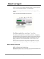
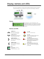
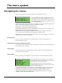
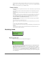
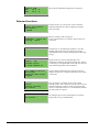
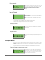
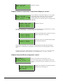
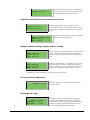
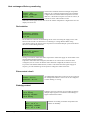
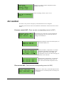
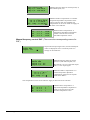
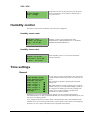
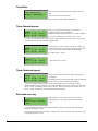
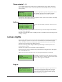
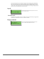
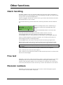
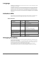
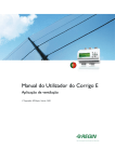
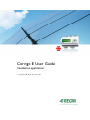
Corrigo E User Guide Ventilation application Copyright AB Regin, Sweden, 2011 About this user guide This user guide covers all the models in the Corrigo E series used with the ventilation application. The document only covers functions which are available to users with Operator access and lower. Revision C, August 2011 Software revision: 3.1 More information More information about Corrigo E can be found in: Manual Corrigo E Ventilation – Complete manual for configuration and maintenance of Corrigo E with ventilation application, available in Swedish, English, German and French. Manual E tool – Manual on how to configure the controllers using the PC software E tool, available in Swedish, English, German and French. Lon-interface variable list – Variable list for the Corrigo E series, available in Swedish and English. Network variables for EXOline and Modbus – Variable list for EXOline and Modbus communication, available in English. CE - Declaration of conformity, Corrigo E The information is available for download from Regin's website, www.regin.se. 2 Corrigo E Ventilation User Guide, revision C About Corrigo E Corrigo E is a series of pre-programmed, configurable controllers for different applications. Corrigo E series comprises three model sizes: 8, 15 or 28 in-/outputs. Available with or without front panel display and buttons. For units without front panel display and buttons a separate, cable-connected terminal E-DSP with display and buttons is available. All normal handling can be done using the display and buttons or from a connected computer running Corrigo E tool and using EXOline for communication. Ventilation application, overview of functions The controller is loaded with programs for controlling a ventilation unit. The temperature controller is based on a supply air PI-controller for heating control with a pre-programmed set of control modes. A number of different control functions as well as analogue and digital input and output functions can be bound to this controller. Certain functions are necessary, others can be seen as functional options. This flexibility means that what is shown in the display may differ from one unit to another, depending on which functions have been selected. Functional choices are not made in the operator level, but in the Admin access level by educated personnel with specialised knowledge. The same applies to other configuration. The program for an air handling unit contains, apart from other things, the following functions: Different temperature control modes Supply air temperature control, with or without outdoor temperature compensation Room temperature control (cascade controller). Extract air temperature control (cascade controller). Seasonal switching between supply air temperature control and room/extract air temperature control. Extra, separate temperature control circuit for after-heaters etc. Corrigo E Ventilation User Guide, revision C 3 With control of: Heat exchanger (liquid connected, plate or rotating) or mixing dampers. Heating coil: Water with frost protection or electric with high temperature limit switch. Chiller: Water-heated or DX, up to 3 steps. Circulation pumps heating, cooling, exchanger. Fan control 1- or 2-speed supply air fans and extract air fans. Frequency controlled supply and extract air fans with pressure or flow control, manual control or external control from a VAV system. Pressure controlled supply air fan with slave connected extract air fan (output dependent or flow dependent). Humidity control Either humidification or dehumidification or both humidification and dehumidification can be used. Timer control For starting and stopping the unit. Up to 5 timer outputs for control of external functions such as lighting, doorlocks etc. Demand control In buildings with strongly varying occupancy the fan speeds or mixing dampers can be controlled by the air quality measured by a CO2/VOC sensor. Support control When using the control function room control or extract air temperature control, it is possible to utilise support-heating and/or support-cooling. Free cooling When this function has been activated, it is used during the summer to cool the building during the night using cool outdoor air thereby reducing the need to run chillers during the day. Enthalpy control Measures and compares the energy content (enthalpy) of the outdoor air and the extract air (temperature and air humidity). When this function is active, the mixing damper signal will be overridden to recirculation if the enthalpy is higher outdoors than indoors. Pretreatment Damper and pump control for preheating or precooling of the outdoor air via an underground intake channel. Cooling recovery If the extract air is colder than the outdoor air and cooling is required, the heat exchanger control is reversed in order to return the cool extract air. Recirculation control Recirculation of air using a supply air fan and recirculation damper, with or without temperature control. Step controllers Heating/Cooling As an alternative to the analogue control of ”Actuator heating Y1” or ”Actuator cooling Y3” step controllers can be used for controlling heating or cooling in steps using digital control. 4 Corrigo E Ventilation User Guide, revision C Display, buttons and LEDs This section is applicable to Corrigo E units with display and buttons but also to the hand terminal E-DSP which can be connected to Corrigo E units without display and buttons. E-DSP Display Regulator vent. sys 2008-11-20 13:30 System: Running Sp: 18.0 Act: 18.2°C The display has 4 rows of 20 characters. It has background illumination. The illumination is normally off, but is activated as soon as a button is pressed. The illumination will be turned off again after a period of inactivity. Buttons and LEDs ARROW UP: Move up a row in the menu. (Increase parameter value) ALARM: Press to view the alarm list. ARROW DOWN: Move down a row in the menu. (Decrease parameter value) CLEAR: Reset/Abort a parameter change unless OK has already been pressed. ARROW RIGHT: Move to a lower menu level. (Move the cursor to the right in the parameter) ALARM LED: Red, flashing light when there is an unacknowledged alarm. Non-flashing light when there is an acknowledged alarm which has not been reset. WRITE LED: Some menus contain settable values. This is indicated by the yellow LED flashing. The value can be changed by pressing OK. ARROW LEFT: Move to a higher menu level. (Move the cursor to the left in the parameter) OK: Open/Activate a selected menu/setting. (Confirm a parameter value) Corrigo E Ventilation User Guide, revision C 5 The menu system Navigating the menus The choice of access level/user access determines which menus are shown. Regulator vent. sys 2008-11-20 13:30 System: Running Sp: 18.0 Act: 18.2°C The start display, the display normally shown, is at the basic level of the menu tree. The appearance of the start display may vary since there are 5 types to choose from during configuration. The text in the first row can also be changed via E tool. Sp and Av are Setpoint and Actual value for the supply air controller. This also applies when using cascaded room temperature or extract air temperature control. Actual value = The current measured temperature. Setpoint value = The desired configured temperature. Pressing ARROW DOWN will move you through the menu choices at this, the lowest level. ARROW UP will move you back through the choices. Which menus are shown depends on which access level you are using (see the section Access rights for more information about logging on to higher levels). The basic access level, the level normally active when you have not logged on, only shows a limited number of menus and submenus: Running mode Here, you can view and set the unit’s running mode, as well as view selected control functions and alarm events. Temperature, Air control and Humidity control Here, relevant values and setpoint values are displayed. Setpoints can only be changed if you have Operator access or higher. Time settings Here, the time, date and set running times are shown. Values can only be changed if you have Operator access or higher. Access rights Here, you can log on to a higher level, log off to the basic level and change the password. Running mode Temperature Air control Humidity control Time settings Access rights A user with Normal access, the basic level, can view a limited selection of menus. The unit’s running mode can be changed and alarms acknowledged. If you have Operator access, you can access more information and change other operation parameters like setpoints and time functions. To get to the next menu level, use ARROW UP and ARROW DOWN to place the display marker opposite the menu you wish to access and press ARROW RIGHT. If you have sufficient log on privileges the display will change to the menu you have chosen. At each level there may be several new menus through which you may move using the ARROW UP and ARROW DOWN buttons. 6 Corrigo E Ventilation User Guide, revision C Sometimes there are further submenus linked to a menu or menu item. This is indicated by an arrow symbol at the right-hand edge of the display. To choose one, use ARROW RIGHT again. To go to a previous menu level, press ARROW LEFT. Change parameters In some menus there are parameters that can be set. This is indicated by the yellow LED with flashing. A quick blinking (2 times/s) indicates that the parameter can be changed using the present user access. A slower blinking (1 time/s) indicates that a higher user access is required to change the parameter. To change a parameter, first press the OK button. If you need a higher user access than you have to change the parameter, a log on menu will be displayed, see below. Otherwise, a cursor will appear at the first settable value. If you wish to change the value, do so by pressing the ARROW UP and ARROW DOWN buttons. In numbers containing several digits you can move between the digits using the ARROW LEFT/RIGHT buttons. When the desired value is displayed press OK. If there are further settable values displayed the cursor will automatically move to the next one. To pass a value without changing it, press RIGHT. To abort a change and return to the initial setting, press and hold the C-button until the cursor disappears. Collected here are a number of menus showing running mode, selected functions, alarm events and status of inputs and outputs. Running mode Running mode Selected functions Alarm events Input/Output Running mode unit The unit’s running mode can be changed without logging on. Running mode Auto The running mode can be set to Auto, Off, Manual reduced run or Manual normal run. The Auto mode should normally be used. Off can be used to stop the unit for service and similar. Manual normal run or Manual reduced run will start the unit even if the timer says that the running mode should be “Off”. If the running mode is set to Off, Manual normal run or Manual reduced run, a C alarm is activated: Running mode Manual. The alarm automatically resets when the running mode is set to Auto again. Corrigo E Ventilation User Guide, revision C 7 Running time SAF: 14.6 EAF: 14.4 Shows the accumulated running times for the fans. h h Selected functions 8 Control function Supply air control Fan control 1-speed In these menus, you can see how some of the most important functions have been configured. Changes cannot be made. Heating: Water Exchanger: Plate exc Cooling: Water Heater, exchanger and cooling type. If one of the functions is not used, it will be shown as ”Not used”. Free cool active: No This function is used during the summer to cool the building night-time using cool outdoor air, thereby reducing the need for cooling during the day and saving energy. Support control Active: Yes CO2/VOC active If time channel on Support control is used for adjusting the room temperature outside of the normal running time. If there is a heating or cooling demand in the room, the unit will start and the temperature will be adjusted. Fire damper function Not active Operation when alarm Stopped The fire function determines the settings for the fire dampers and the unit’s running mode when a fire alarm is activated. Frost protection Active Cooling recovery Not active Frost protection is normally always used in water heating systems. The cooling recovery function reverses the heat exchanger in order to return cooling from the extract air when the extract air is colder than the outdoor air and cooling is required. External setpoint Not active An analogue input can be configured for an external setpoint device e.g. TG-R4/PT1000. Corrigo E Ventilation User Guide, revision C Alarm events 24 Nov 14:32 Malf. SAF B Alarm log which contains the 40 latest alarm events. The most recent event is listed first. The alarm log can only be used for viewing the alarm history. Alarms are handled in a special area, see the section Alarm handling. Acknowledged Inputs/Outputs AI DI UI AO DO These menus show the current values for all configured inputs and outputs. These are read-only menus. No changes can be made here. Universal inputs can be configured as either analogue or digital inputs. Analogue inputs and digital outputs are shown here as examples. Analogue inputs AI1: AI2: AI3: AI4: 18.5 20.3 28.2 19.9 Outdoortemp Supplytemp Frost.temp Room1.temp The current values for the analogue inputs and outputs are shown here. Digital outputs DO1:Off DO2:Off DO3: On DO4:Off SAF EAF SAF EAF 1/1-speed 1/1-speed 1/2-speed 1/2-speed This menu shows if the digital inputs and outputs are On or Off. Temperature Here you can view all actual and setpoint values for temperature control. The menu is visible to all users, regardless of log on level. However, to make changes you need at least Operator authority. The following menus are available providing that the corresponding input is activated: Setpoint Supply air temperature control Outdoortemp.:18.4°C Supply air temp Act.: 19.8°C Setp Setp.: 20.0°C Setpoint Supply air control. Here, Actual and Setpoint values are shown, as well as the outdoor temperature if a outdoor sensor has been configured. This is a read-only menu. No settings can be made here. Corrigo E Ventilation User Guide, revision C 9 Supply air temp Setp.: 20.0°C Submenu: Setpoint. Setpoint Outdoor temperature compensated Supply air control Outdoor temp.:18.4°C Supply air temp Actual: 19.8°C Setp Setp.: 20.0°C Outdoor -20.0°C -15.0°C -10.0°C Setpoint Outdoor compensated supply air control. Here, Actual and Setpoint values are shown, as well as the outdoor temperature if a outdoor sensor has been configured. This is a read-only menu. No settings can be made here. comp. setp. = 25.0°C = 24.0°C = 23.0°C Submenus: Setpoint In control modes Supply air control/Room control and Supply air control/Extract air control , the setpoint relationship is used when supply air control is active. Outdoor -5.0°C 0.0°C 5.0°C comp. setp. = 23.0°C = 22.0°C = 20.0°C Outdoor comp. setp. 10.0°C = 19.0°C 20.0°C = 18.0°C Use the eight breakpoints to generate a setpoint / outdoor temperature relationship. In-between-values are calculated using straight lines between breakpoints. Setpoints for temperatures lower than the lowest breakpoint and higher than the highest breakpoint are calculated by extending the line between the two last breakpoints at either end. Example: At the lower end the setpoint is increasing by 1°C for every 5 °C lowering of the outdoor temperature. So the setpoint at –23°C would be 25°C + .6x 1.0°C = 25.6°C. Setpoint Cascaded Room temperature control Room temp.1 Actual: 22.0°C Setpoint: 21.5°C Setpoint Cascaded room temperature control. -> In control mode Supply air control/Room control, the setpoint is used when cascade connected room control is active. If cascade control max/min supply setp. Max: 30.0°C Min: 12.0°C 10 Corrigo E Ventilation User Guide, revision C Submenu for setting the min and max limitation temperatures for the supply air. Room temp.2 Actual: 21.8°C If two room sensors have been configured you will also get this menu. The controller uses the average temperature of the two sensors. Setpoint Cascaded extract air temperature control Extract air temp. Actual: 21.0°C Setpoint: 21.1°C Setpoint Cascaded extract air temperature control. In control mode Supply air control/Extract air control, the setpoint is used when cascaded extract air control is active. If cascade control max/min supply setp. Max: 30.0°C Min: 12.0°C Submenu for setting the min and max limitation temperatures for the supply air. Support control heating / Support control cooling Support heating Room temp for Start: 15.0°C Stop: 21.0°C Support control is normally used when room temperature control or extract air control has been configured, to prevent a too large offset in temperature when the unit is “Off”. Support cooling Room temp for Start: 30.0°C Stop: 28.0°C “Support control Heating” or “Support control Cooling” will run if support control is configured, the running mode is "Off" (timer control OFF and not in extended running) and if conditions call for support control. Minimum run time is settable 0 to 720 minutes (FS= 20 minutes). Frost protection temperature Frost protection Actual: 30.9°C Relevant value for the water temperature at the frost protection sensor. Exchanger de-icing De-icing exchanger Actual: 11.2°C Setpoint: -3.0°C Hysteresis: 1.0°C This menu is shown if exchanger de-icing has been configured. If the temperature at the de-icing sensor drops below the setpoint value, the de-icing function is started. It is stopped when the temperature has risen above the setpoint plus the set differential. Corrigo E Ventilation User Guide, revision C 11 Heat exchanger efficiency monitoring Efficiency exch. Actual: 93% Output exchanger Actual: 100% The function calculates the heat exchanger temperature efficiency in % when the output signal to the exchanger is higher than 5% and the outdoor temperature is lower than 10°C. The function requires an extract air sensor, an exhaust air sensor and an outdoor sensor. When the control signal is lower than 5% or the outdoor temperature is higher than 10°C the display will show 0%. Recirculation Offset SAF when frequency control and recirculation: 0.0 Pa Recirculation is a function for distributing the air in the room using the supply air fan. The function can be used even when there is no heating or cooling demand. When using recirculation control, the extract air fan stops and a recirculation damper opens which allows the air to circulate through the unit. Temp.setpoint when recycling (supply/ extract/room) 18.0°C During recirculation, offset SAF makes it possible to add to the supply air fan an offset to the setpoint during normal operation. If pressure control has been configured, the offset is set in Pa. If flow control has been configured, it is set in m3/h. If manual control has been configured, the offset is set in %. If you have selected the Offset function, which is a deviation from the regular supply air setpoint, you will instead be given the option to change this offset value here. Extra control circuit Extra control circuit Actual: 21.2°C Setpoint: 20.0°C An independent temperature control circuit for control of for example after-heaters. The circuit can be configured to either heating or cooling. Enthalpy control Enthalpy indoor: 35.5 kJ/kg Enthalpy outdoor: 36.4 kJ/kg Outdoortemp Act.: 19.2 °C Humidity outdoor Act.: 51.1 % RH 12 Corrigo E Ventilation User Guide, revision C Enthalpy control is a function for overriding the mixing damper output signal to recirculation if the enthalpy is higher outdoors than indoors. Submenu for reading of outdoor temperature and outdoor air humidity. Indoortemp Act.: 19.9°C Humidity indoor Act: 44.3 % RH Submenu for reading of indoor temperature and air humidity in the room. Override Cool Recovery due to Enthalpy: Active Shows if enthalpy control is active or not. Air control This menu is only shown if frequency controlled fans have been configured. Depending on the choice of fan control, different combinations of the menus below will be shown. Pressure control SAF. (There are also corresponding menus for EAF) Pressure contr. SAF Actual: 480 Pa Setp.: 490 Pa Setpoint Pressure control Here, Actual and Setpoint values are displayed. This is a read-only menu. No settings can be made here. Pressure contr. SAF Setp 1/1: 490 Pa Setp 1/2: 300 Pa Submenu Setpoint values for normal speed (1/1) and reduced speed (1/2). Outd. comp. setp. -20 °C = -50 Pa 10 °C = 0 Pa Act. Comp: -5 Pa Submenu Outdoor compensation. An outdoor temperature dependent compensation of the pressure setpoint value can be added. The compensation can be set for either the supply air fan alone or for both fans. Comp.sens.:Roomtemp1 15 °C = 0 Pa 20 °C = 0 Pa 25 °C = 0 Pa Submenu Extra compensation. A temperature dependent compensation similar to the one above but with selectable temperature source. Flow control SAF. (There are also corresponding menus for EAF) Flow control SAF Actual: 1800 m3/h Setp.: 2000 m3/h Setpoint Flow control. Here, Actual and Setpoint values are displayed. This is a read-only menu. No settings can be made here. Corrigo E Ventilation User Guide, revision C 13 Flow control SAF Setp 1/1: 2000 m3/h Setp 1/2: 1000 m3/h Submenu Setpoint values for normal speed (1/1) and reduced speed (1/2). Outdoor comp. setp. -15 °C =-200.0 m3/h 10 °C = 0.0 m3/h Act. comp: 0.0 m3/h Submenu Outdoor compensation. An outdoor temperature dependent compensation of the pressure setpoint value can be added. The compensation can be set for either the supply air fan alone or for both fans. Comp.sens.:Roomtemp1 15 °C = 0 m3/h 20 °C = 0 m3/h 25 °C = 0 m3/h Submenu Extra compensation. A temperature dependent compensation similar to the one above but with selectable temperature source. Manual frequency control SAF. (There are also corresponding menus for EAF) Frequency control manual SAF Output: 75% Setpoint Fixed output signal. Here, Actual and Setpoint values are displayed. This is a read-only menu. No settings can be made here. Frequency control manual SAF Output 1/1: 75% Output 1/2: 50% Submenu Setpoint values for normal speed (1/1) and reduced speed (1/2). Outdoor comp. outp. -20 °C = -40 % 10 °C = 0 % Act. Comp: 0 % Submenu Outdoor compensation. An outdoor temperature dependent compensation of the pressure setpoint value can be added. The setpoint is set in % of the full output. 100 % = 10 V output signal. The compensation can be set for either the supply air fan alone or for both fans. Comp.sens.:Roomtemp1 15 °C = 0 % 20 °C = 0 % 25 °C = 0 % 14 Corrigo E Ventilation User Guide, revision C Submenu Extra compensation. A temperature dependent compensation similar to the one above but with selectable temperature source. CO2 / VOC CO2 Actual:920ppm Setp.:1000pm In applications with varying occupancy, the fan speed can be controlled by the air quality as measured by a CO2/VOC-sensor. Humidity control This menu is only shown if humidity control has been configured. Humidity sensor room Humidity room Actual: 51.9% RH Setp.: 50.0% RH Humidity control can be configured as either Humidification or Dehumidification or as combined Humidification/Dehumidification. Humidity sensor duct Humidity duct Actual: 72.2% RH Max.limit: 80.0% RH Hyst.: 20.0% RH A duct humidity sensor is only used for maximum limitation function. Time settings General Time/Date Timer Normal speed Timer Reduced speed Extended running Timer output 1 Timer output 2 Timer output 3 Timer output 4 Timer output 5 Holidays Corrigo has a year-base clock function. This means that a week-schedule with holiday periods for a full year can be set. The clock has an automatic summertime/wintertime change-over. Individual schedules for each week-day plus a separate holiday setting. Up to 24 individual holiday periods can be configured. A holiday period can be anything from one day up to 365 days. Holiday schedules take precedence over other schedules. Each day has up to two individual running periods. For two-speed fans and pressure controlled fans there are daily individual schedules for normal speed and reduced speed, each with up to two running periods. Up to 5 digital outputs can be used as timer controlled outputs. Each with individual weekschedules with two activation periods per day. These outputs can be used to control lighting, doorlocks etc. Only outputs which have been configured will be shown. Corrigo E Ventilation User Guide, revision C 15 Time/Date Current time: 18:21 Date: 2009-06-10 Weekday: Wednesday This menu shows and permits the setting of time and date. Time is shown in 24-hour format. Date is shown in the format YY-MM-DD. Timer Normal speed Normal speed Monday Per.1: 07:00 – 16:00 Per.2: 00:00 - 00:00 There are 8 separate setting menus, one for each weekday and one extra for holidays. Holiday schedules take precedence over other schedules. For 24 hour running, set a period to 0:00 – 24:00. To inactivate a period, set the time to 00:00 – 00:00. If both periods of a day are set to 0:00 – 0:00, the unit will not run at normal speed that day. Normal speed Monday Per.1: 07:00 – 16:00 Per.2: 22:00 - 24:00 If you want to run the unit from one day to another, e.g. from Mon 22:00 to Tue 09:00, the desired running time for the various days must be entered individually. Normal speed Tuesday Per.1: 00:00 – 09:00 Per.2: 00:00 - 00:00 ... then Tue 00:00 – 09:00. First Mon 22:00 – 24:00.... Timer Reduced speed Reduced speed Sunday Per.1: 10:00 – 16:00 Per.2: 00:00 - 00:00 These settings will be ignored if single speed fans are configured. Should periods for normal speed and periods for reduced speed overlap, normal speed takes precedence. There are 8 separate setting menus, one for each weekday and one extra for holidays. Holiday schedules take precedence over other schedules. For 24 hour running, set a period to 00:00 – 24:00. To disable a period, set it to 00:00 – 00:00. If both periods of a day are set to 00:00 – 00:00, the unit will not run at Reduced speed that day. Extended running Extended running 60 min Time in ext. running 0 min Digital inputs can be used to force the unit to start although the timer says the running mode should be “Off”. For 2-speed fans and pressure/flow controlled fans, inputs for normal speed and reduced speed can normally be used. The unit will run for the set time. If the running time is set to 0 the unit will only run as long as the digital input is closed. 16 Corrigo E Ventilation User Guide, revision C Timer outputs 1…5 Up to 5 digital outputs can be used as timer controlled outputs. Only outputs which have been configured will be shown. Each with individual week-schedules with two activation periods per day. Timer output 2 Wednesday Per.1: 05:30 - 08:00 Per.2: 17:00 – 23:00 Each timer output has 8 separate setting menus, one for each weekday and one extra for holidays. Holiday schedules take precedence over other schedules. If the function Recirculation has been configured, Timer output 5 can be used for controlling start/stop of the Recirculation function. Holidays Holidays 1: 01-01 2: 09-04 3: 01-05 (mm:dd) – 02-01 – 12-04 – 01-05 Up to 24 separate holiday periods for a full year can be set. A holiday period can be any number of consecutive days from one and upwards. The dates are in the format: MM-DD When the current date falls within a holiday period, the scheduler will use the settings for the weekday “Holiday”. Access rights There are four different access levels, Normal level which has the lowest access and does not require logging on, Operator level, Service level and Admin level which has the highest access. The choice of access level determines which menus are shown, as well as which parameters can be changed in the displayed menus. The basic level only permits changes in Running mode and gives read-only access to a limited number of menus. Operator level gives access to all menus except Configuration. Service level gives access to all menus except the submenus Configuration/In- and Outputs and Configuration/System. Admin level gives full read/write access to all settings and parameters in all menus. Log on Log off Change password Repeatedly press down-arrow when the start-up display is shown until the arrow-marker to the left of the text-list points to Access rights. Press RIGHT. Log on Enter password:**** Actual level: None In this menu it is possible to log on to any access level by entering the appropriate 4-digit code. The log on menu will also be displayed should you try to gain access to a menu or try to do an operation requiring higher authority than you have. Log on Corrigo E Ventilation User Guide, revision C 17 Press the OK button and a cursor marker will appear at the first digit position. Repeatedly press the UP button until the correct digit is displayed. Press the RIGHT button to move to the next position. Repeat the procedure until all four digits are displayed. Then press OK to confirm. After a short while the text on the line: Present level will change to display the new log on level. Press the LEFT button to leave the menu. Log off Log off? No Actual level:Admin Use this menu to log off from the present level to the basic "no-log on" level. Automatic logoff If the access level is Operator, Service or Admin, the user will automatically be logged off to Normal after a settable time of inactivity. The time is settable. Change password Change password for level:Operator New password: **** 18 Corrigo E Ventilation User Guide, revision C You can only change the password for access levels lower or equal to the presently active level. Other functions Alarm handling If an alarm condition occurs, the red alarm LED on the front panel of units with display or the alarm LED on a connected display unit will start flashing. The LED will continue to flash as long as there are unacknowledged alarms. Alarms are logged in the alarm list. The list shows type of alarm, date and time for the alarm and the alarm class (A, B or C alarm). To access the alarm list, press the alarm button, the front panel button with the red buttontop. Sensor error Supply Air temp 24 Aug 10:43 Class:B Reset If there are multiple alarms, this is indicated by up / down arrow symbols at the right-hand edge of the display. Use the UP and DOWN buttons to access the other alarms. At the left end of the bottom display line the alarm status is shown. For active, unacknowledged alarms the space is blank. For alarms that have reset the text: Acknowledged, still active or blocked alarms are indicated by Acknowledged or Blocked. Alarms are acknowledged by pressing the OK button. You are then given the choice of acknowledging the alarm or blocking the alarm. Acknowledged alarms will remain on the alarm list until the alarm input signal resets. Blocked alarms remain on the alarm list until the alarm has reset and the block has been removed. New alarms of the same type will not be activated as long as the block remains. Since blocking alarms can be potentially hazardous, you need a high log on authority to block alarms. Class A and B alarms will activate alarm output(s) if these have been configured. Class C alarms do not activate the alarm output(s). Class C alarms are removed from the alarm list when the alarm input resets even if the alarm has not been acknowledged. Free text If RIGHT is pressed once when the start-menu is shown, a menu showing text of your choice is displayed. The text can be used to show information concerning the commissioning company, name and phone number to service personnel etc. The easiest way to enter text is to use E tool, but the buttons can also be used. Up to 4 lines of 20 characters can be entered. Revision numbers If RIGHT is pressed twice when the start-menu is shown, a menu showing the program revision number and ID number is displayed. Corrigo E Ventilation User Guide, revision C 19 Language If RIGHT is pressed three times when the start-menu is shown, a menu is displayed in which the language can be changed. The different language files are stored in the application memory and are downloaded to the work memory. If a Corrigo via E tool has been reloaded with a newer program revision than the factory revision, the controller will not allow language files to be downloaded from the application memory. This is because there is a risk that the language files are not compatible with the new revision. Therefore, you are limited to the two languages you have downloaded using E tool. Indication LEDs Status indication can be found in the upper left corner of the controller. For controllers with display, the alarm indication and change mode LEDs are located in the keypad area. Status indication Designation Colour Description Tx Green Port 1, Transmitting Rx Green Port 1, Receiving Serv (-Lon models) Yellow Service LED LON, commissioning LAN (-Web models) Yellow/Green Green: Connected to other network equipment Blinking green: Network traffic Blinking yellow: For identifying P/B (Power/Battery) Green/Red Power on/Battery error Red Alarm indication Yellow Change mode Controllers with built-in display: Changing the battery Corrigo E has an internal battery to ensure the operation of the memory and real-time clock in the event of a power failure. When the alarm ”Internal Battery” is activated and the battery LED lights up red, the battery has become too weak and needs to be changed. Nonetheless, due to a backup capacitor, the controller will function at least 10 minutes without power supply. Since changing the battery requires knowledge of proper ESD protection, as well as dismantling and opening of the unit, this should be handled by skilled service personnel. 20 Corrigo E Ventilation User Guide, revision C Index Inputs/Outputs, 9 A L Access rights, 17 Air control, 13 Alarm events, 9 Alarms Alarm handling, 19 Language, change, 20 LEDs, 20 Log off, 18 Log on, 17 B M Buttons and LEDs, 5 Menus, 6 C N Changing the battery, 20 Navigating the menus, 6 D O Date/Time, 16 Demand control Setpoint, 15 Display, 5 Other functions, 19 E Password, 18 Enthalpy control, 12 Extended running, 16 R F Fans Timer output ½ speed, 16 Timer output 1/1 speed, 16 Functions, overview, 3 H Holidays, 17 Humidity control, 15 Setpoint, 15 I Indicators, 20 Information screen, 19 P Revision number, 19 Running mode, 7 Running mode unit, 7 S Selected functions, 8 Setpoint fan control, 13 Setpoint humidity control, 15 Setpoints temperature, 9 T Temperature, 9 Time settings, 15 Time/Date, 16 Timer output ½ speed, 16 Timer output 1/1 speed, 16 Timer outputs, 17 R E G I N – T H E C H A L L E N G E R I N B U I L D I N G A U T O M A T I O N AB Regin Head office Box 116, S-428 22 Kållered, Phone: +46 31 720 02 00 [email protected] Sweden Fax: +46 31 720 02 50 www.regin.se Germany France Spain Singapore Hong Kong Regin Controls Asia Pacific Pte Ltd Regin Controls Hong Kong Ltd 66 Tannery Lane Room 2901 # 03-04 Sindo Building EW International Tower Singapore 347805 120 Texaco Road Phone: +65 6747 8233 Tsuen Wan, NT [email protected] Hong Kong www.regin.com.sg Phone: +852 2407 0281 RICCIUS + SOHN GmbH Regin Controls SARL Regin Ibérica, S.A. Haynauer Str. 49 32 rue Delizy C/Arganda 18 local D-12249 Berlin F-93500 Pantin E-28005 Madrid Phone: +49 30 77 99 40 Phone: +33 1 41 71 00 34 Phone: +34 91 473 27 65 [email protected] [email protected] [email protected] www.riccius-sohn.eu www.regin.fr www.reginiberica.com [email protected] www.regin.com.hk