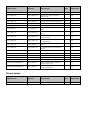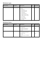
1
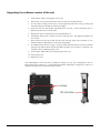
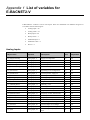
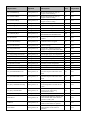
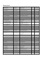
E-BACNET2-V manual © Copyright AB Regin, Sweden, 2012 DISCLAIMER The information in this manual has been carefully checked and is believed to be correct. Regin, however, makes no warranties in regard to the contents of this manual. Users are requested to report errors, discrepancies or ambiguities to Regin, so that corrections may be made in future editions. The information in this document is subject to change without prior notification. The software described in this document is supplied under licence by Regin and may be used or copied only in accordance with the terms of the licence. No part of this document may be reproduced or transmitted in any form or fashion, electronically or mechanically, without the express, written permission of Regin. COPYRIGHT AB Regin. All rights reserved. TRADEMARKS Corrigo E is a registered trademark of AB Regin. Other product names mentioned in this document are used for identification purposes only and may be the registered trademarks of their respective companies. Revision B, December 2012 Table of contents CHAPTER 1 ABOUT E-BACNET2-V ................................................................................................... 4 CHAPTER 2 WIRING ....................................................................................................................... 5 CHAPTER 3 CONFIGURATION ......................................................................................................... 6 Refresh ......................................................................................................................................... 6 Wink ............................................................................................................................................. 6 Edit / Change settings .................................................................................................................. 6 Upgrading the software version of the unit ................................................................................ 8 APPENDIX 1 LIST OF VARIABLES FOR E-BACNET2-V ..................................................................... 10 Analog Inputs ............................................................................................................................. 10 Analog Values ............................................................................................................................ 11 Binary Inputs .............................................................................................................................. 13 Binary Values ............................................................................................................................. 15 Multistate Inputs ....................................................................................................................... 16 Multistate Values ....................................................................................................................... 16 Chapter 1 About E-BACNET2-V E-BACNET2-V is a pre-configured converter for connecting a Corrigo E running a ventilation application version 3.0 or later to a SCADA system. The converter has a pre-configured device id and a fixed IP address of 192.168.92.92. Communication with Corrigo E takes place via the PLA:ELA address 254:254. To change these settings, see chapter 3. The Corrigo E controller is connected to the converter with the supplied cable and communicates with the SCADA system via the Ethernet port on the converter. Technical data Supply voltage ...................................................................................................... 12...48 V DC Power consumption .......................................................................................................... 4.5 W Dimensions .................................................................................................... 77 x 111 x 26 mm Weight ............................................................................................................................... 190 g Mounting ............................................................................................................................ Wall Ambient temperature ............................................................................................... -10...+60°C Storage temperature ............................................................................................... -20...+80°C Ambient humidity .................................................................................................. 5…95 % RH Ethernet connections ............................................. Two, automatic change-over 10/100 Mbps Serial connections ............................................................ Two RS-232/422/485 (9-pole D-sub) 4 About E-BACNET2-V E-BACNET2-V manual, revision B Chapter 2 Wiring Mount the converter directly on a flat surface, e.g. using a mounting screw (not included). A kit for DIN-mounting is also available as an option. The transformer should preferably be mounted using a cable tie. Connect the RS485 cable marked E-CABLE-BACNET to the S0/P1 port on the converter and to the B, A and N terminals (50, 51 and 52) on the Corrigo. Connect E-BACNET2-V to the local network by connecting the RJ45 cable between the ETH0/LAN1 port of the converter and a network port. The converter may also be connected directly to a computer, but this requires a crossover RJ45 cable (not included). Connect the power supply to the converter and to the Corrigo E. Please note when wiring the supply voltage into the converter: V + is marked while V - is entirely black. It will take approx. one minute for the converter to start up. When the unit is ready, the Ready light will be lit. If the Corrigo connected has the PLA:ELA address 254:254, the converter will begin communicating. This is indicated by the S0/P1 TX and RX lights blinking. The unit is now also available in the BACnet network. Wiring for black E-BACNET2-V E-BACNET2-V manual, revision B Wiring for blue E-BACNET2-V Chapter 2 Wiring 5 Chapter 3 Configuration All configuration takes place via the software tool E-BACNET2 configuration software for Microsoft Windows (XP, Vista or Windows 7). The software tool is available for download from Regin's website, www.regin.se. Once the program is started, it will scan the network for EBACNET2-V units. All available converters connected to the network are displayed. Refresh Pressing the Refresh button will update the list of converters. Wink Wink is a function that can be used to ensure that the correct physical converter has been selected in the configuration tool. By selecting a converter in the list and clicking the Wink button, the LED:s on the converter will blink and a short beep will be heard. Edit / Change settings Only a converter with the value BACnet = “Yes” can be edited. To edit the settings of a unit, select it in the list of available converters and click Edit. 6 Configuration E-BACNET2-V manual, revision B This will display the following window, containing the settings that can be made: IP It is possible either to let the network’s DHCP server assign the converter an IP address or to assign it a fixed IP address. BACnet Permits setting of: Device ID: The device ID number of the object. Location: Place, e.g. ”room23”. Description: Description, e.g. ”AHU01” (air handling unit 01). Name: The desired name of the converter. If adding a dollar sign ($) after the name, device ID will be automatically added after it. UDP Port. BACnet IP standard is 47808. The checkbox “Foreign device” is used when E-BACNET2-V is to be connected to another IP network. It is then neccessary to state the BBMD address. An example of this is when EBACNET2-V is stand-alone and connecting to a SCADA system over the Internet. The BBMD address is handled by the network administrator. Station Used to state the PLA:ELA address for Corrigo E on the RS485 side. The Corrigo E standard address is 254:254. The “Debug” checkbox is used to set the converter to debug mode. This function requires a special version of the converter, and is not normally used. Once all settings has been made, press ”Save” in order to upload the settings to the converter. E-BACNET2-V manual, revision B Chapter 3 Configuration 7 Upgrading the software version of the unit 1. Power off the unit by removing the power cord. 2. Remove the cover by unscrewing the screws on each side (see photo below). 3. If a SD card is already present, eject it at the right-hand side of the unit by pressing and then releasing the card. Mail the card back to Regin. 4. Insert the new SD card labeled “E-BACNET2-V 2.0-1-09” or later and firmly press it. Release pressure once a click is heard. 5. Reattach the power cord and power up the E-BACNET2-V. 6. Immediately after power is turned on, the unit will beep once. The upgrade procedure has now started. 7. Wait between 30 and 60 seconds and the unit will beep again. The procedure is now finished, and the E-BACNET2-V unit has been upgraded. 8. If communication with the Corrigo is working, the Ready LED will be lit some 20 seconds after the beep and the S0/P1 TX and RX LEDs will flash. If no Corrigo is connected, only the S0/P1 TX led is flashing (about 1 Hz). 9. Power off the E-BACNET-V by removing the power cord. 10. Eject the SD card. 11. Replace the cover. The E-BACNET2-V now has factory default IP settings, but any user configuration, such as BACnet device ID, location, etc., is left unchanged. Run the E-BACNET2 configuration software to change IP settings and to verify the firmware version. 8 Configuration E-BACNET2-V manual, revision B Appendix I Appendix 1 List of variables for E-BACNET2-V E-BACNET2-V contains a total of 184 objects. These are distributed over different categories in accordance with the following list: Analog Input = 40 Analog Value = 41 Binary Input = 98 Binary Value = 1 Multistate Input = 1 Multistate Value = 2 Device = 1 Analog Inputs Object name Object ID Description Unit Adjustable Cor_SupplyAirTemp Analog Input, 0 Supply air temperature °C No Cor_ExtractAirTemp Analog Input, 1 Extract air temperature °C No Cor_RoomTemp1 Analog Input, 2 Room temperature 1 °C No Cor_RoomTemp2 Analog Input, 3 Room temperature 2 °C No Cor_ExhaustAirTemp Analog Input, 4 Exhaust air temperature °C No Cor_ExtraSensor Analog Input, 5 External sensor/setpoint device, depending on the configuration. °C No Cor_SAFPressure Analog Input, 6 Current pressure, supply air Pa No Cor_EAFPressure Analog Input, 7 Current pressure, extract air Pa No Cor_DeIcingTemp Analog Input, 8 De-icing temperature °C No Cor_FrostprotectionTemp Analog Input, 9 Frost protection temperature °C No Cor_CO2Sensor Analog Input, 10 CO2 sensor ppm No Cor_HumidityRoom Analog Input, 11 Humidity, room RH No Cor_HumidityDuct Analog Input, 12 Humidity, duct RH No Cor_ExtraUnitTemp Analog Input, 13 Extra controller, temperature °C No Cor_ExtSAFControl Analog Input, 14 Frequency control, manual SAF % No Cor_ExtEAFControl Analog Input, 15 Frequency control, manual EAF % No Cor_HumidityOutDoor Analog Input, 16 Humidity outdoor RH No Cor_SAFAirFlow Analog Input, 17 Frequency control, air flow SAF 3 m /h No 3 Cor_EAFAirFlow Analog Input, 18 Frequency control, air flow EAF m /h No Cor_HeatCV1 Analog Input, 19 Current output Y1-heating V No Cor_ExchCV1 Analog Input, 20 Current output Y2-exchanger V No Cor_CoolCV1 Analog Input, 21 Current output Y3-cooling V No Cor_SAF Analog Input, 22 Current output frequency converter SAF V No Object name Object ID Description Unit Adjustable Cor_EAF Analog Input, 23 Current output EAF V No Cor_Humidity Analog Input, 24 Current output dehumidification/humidification V No Cor_Split Analog Input, 25 Current output split V No Cor_ExtraSeqCV1 Analog Input, 26 Current output Y4-extra sequence V No Cor_Efficiency Analog Input, 27 Heat exchanger efficiency % No Cor_SAFRunTime Analog Input, 28 Running time SAF h No Cor_EAFRunTime Analog Input, 29 Running time EAF h No Cor_SupplyPID_SetP Analog Input, 30 Calculated supply air setpoint at outdoor compensated setpoint °C No Cor_SupplyPID_Output Analog Input, 31 Supply air controller output signal % No Cor_ExhaustPID_Output Analog Input, 32 Extract air controller output signal % No Cor_SAFPID_Output Analog Input, 33 Output signal SAF % No Cor_EAFPID_Output Analog Input, 34 Output signal EAF % No Cor_FrostPID_Output Analog Input, 35 Warming controller output signal % No Cor_CO2PID_Output Analog Input, 36 CO2 controller output signal % No Cor_RoomPID_Output Analog Input, 37 Room controller output signal % No Cor_DeIcePID_Output Analog Input, 38 De-icing controller output signal % No Cor_HumidityPID_Output Analog Input, 39 Humidity controller output signal % No Object name Object ID Description Unit Adjustable Cor_SupplySetpoint Analog Value, 0 Supply air setpoint if supply air control is selected °C Yes Cor_ExtractSetpoint Analog Value, 1 Extract air setpoint if extract air control is selected °C Yes Cor_SAFFullspeedPressure Analog Value, 2 Setpoint normal speed supply air fan, frequency control pressure Pa Yes Cor_SAFHalfspeedPressure Analog Value, 3 Setpoint reduced speed supply air fan, frequency control pressure Pa Yes Cor_EAFFullspeedPressure Analog Value, 4 Setpoint normal speed extract air fan, frequency control pressure Pa Yes Cor_EAFHalfspeedPressure Analog Value, 5 Setpoint reduced speed extract air fan, frequency control pressure Pa Yes Cor_CO2Setpoint Analog Value, 6 Setpoint CO2 ppm Yes Cor_SAFFullspeedAirFlow Analog Value, 7 Setpoint normal speed supply air fan flow m3/h Yes Cor_SAFHalfspeedAirFlow Analog Value, 8 Setpoint reduced speed supply air fan flow m3/h Yes Cor_EAFFullspeedAirFlow Analog Value, 9 Setpoint normal speed extract air fan flow m3/h Yes Cor_EAFHalfspeedAirFlow Analog Value, 10 Setpoint reduced speed extract air fan flow m3/h Yes Cor_NeedHeatStart Analog Value, 11 Room temperature for start of support control heating °C Yes Analog Values Object name Object ID Description Unit Adjustable Cor_NeedHeatStop Analog Value, 12 Room temperature for stop of support control heating °C Yes Cor_NeedCoolStart Analog Value, 13 Room temperature for start of support control cooling °C Yes Cor_NeedCoolStop Analog Value, 14 Room temperature for stop of support control cooling °C Yes Cor_DeIcingSetpoint Analog Value, 15 Setpoint de-icing °C Yes Cor_DeIcingHyst Analog Value, 16 Hysteresis de-icing °C Yes Cor_HumiditySetpoint Analog Value, 17 Setpoint humidity RH Yes Cor_HumidityMaxDuct Analog Value, 18 Max. duct humidity RH Yes Cor_HumidityHyst Analog Value, 19 Hysteresis for start of dehumidification/humidification RH Yes Cor_RoomSetP Analog Value, 20 Room setpoint if using room control °C Yes Cor_FrostProtSPStop Analog Value, 21 Setpoint frost protection if the ventilation unit is stopped °C Yes Cor_FrostProtPGain Analog Value, 22 P-band frost protection function (when running) °C Yes Cor_SupplyMaxDiff Analog Value, 23 Alarm max. difference between supply air setpoint and actual value °C Yes Cor_SupplyLowAlarmLimit Analog Value, 24 Alarm low supply air temperature °C Yes Cor_SupplyHighAlarmLimit Analog Value, 25 Alarm high supply air temperature °C Yes Cor_EfficiencyLowLimit Analog Value, 26 Alarm low efficiency % Yes Cor_FrostLimit Analog Value, 27 Alarm limit frost protection °C Yes Cor_RoomHighLimit Analog Value, 28 Alarm high room temperature °C Yes Cor_RoomLowLimit Analog Value, 29 Alarm low room temperature °C Yes Cor_ExtractAirTempHigh Analog Value, 30 Alarm high extract air temperature °C Yes Cor_ExtractAirTempLow Analog Value, 31 Alarm low extract air temperature °C Yes Cor_SAFMaxDiffPressure Analog Value, 32 Alarm max. difference between pressure setpoint and actual value SAF Pa Yes Cor_EAFMaxDiffPressure Analog Value, 33 Alarm max. difference between pressure setpoint and actual value EAF Pa Yes Cor_RecycleSetP Analog Value, 34 Setpoint recirculation °C Yes Cor_RecycleMaxRoomTemp Analog Value, 35 Stop recirculation function if the room temperature exceeds the set value °C Yes Cor_RecycleSAFOffset Analog Value, 36 Pressure/flow setpoint offset for the supply air fan when using recirculation control Pa Yes Cor_OutDoorTemp Analog Value, 37 Outdoor temperature °C Yes AlaAcknow Analog Value, 38 Acknowledge alarm by entering the alarm number XX of the alarm in question (AlaPt_XX) - Yes AlaBlock Analog Value, 39 Block alarm by entering the alarm number of the alarm in question - Yes AlaUnblock Analog Value, 40 Unblock alarm by entering the alarm number of the alarm in question - Yes Binary Inputs Object name Object ID Description Unit Adjustable Cor_SAFStart1 Binary Input, 0 Start signal SAF normal - No Cor_EAFStart1 Binary Input, 1 Start signal EAF normal - No Cor_SAFStart2 Binary Input, 2 Start signal SAF reduced - No Cor_EAFStart2 Binary Input, 3 Start signal EAF reduced - No Cor_HeatPumpStart Binary Input, 4 Start signal P1-heater - No Cor_ExchPumpStart Binary Input, 5 Start signal P1-exchanger - No Cor_CoolPumpStart Binary Input, 6 Start signal P1-cooler - No Cor_SumAlarm Binary Input, 7 Sum alarm A + B - No Cor_SumAlarmA Binary Input, 8 Sum alarm A - No Cor_SumAlarmB Binary Input, 9 Sum alarm B - No Cor_SAFFrequencyStart Binary Input, 10 Start signal SAF frequency converter - No Cor_EAFFrequencyStart Binary Input, 11 Start signal EAF frequency converter - No Cor_NeedHeatActive Binary Input, 12 Support control heating active - No Cor_NeedCoolActive Binary Input, 13 Support control cooling active - No Cor_DemandCO2Active Binary Input, 14 CO2 running mode active - No Cor_ExtendedRunActiveFull Binary Input, 15 Extended running normal active - No Cor_ExtendedRunActiveHalf Binary Input, 16 Extended running reduced active - No Cor_DeIcingActive Binary Input, 17 De-icing function active - No Cor_RecycleRunActive Binary Input, 18 Recirculation function active - No Cor_AlaPt_1 Binary Input, 19 Malfunction supply air fan: 0 = No alarm 1 = Alarm - No Cor_AlaPt_2 Binary Input, 20 Malfunction extract air fan - No Cor_AlaPt_3 Binary Input, 21 Run error P1-heater - No Cor_AlaPt_4 Binary Input, 22 Run error P1-cooler - No Cor_AlaPt_5 Binary Input, 23 Run error P1-exchanger - No Cor_AlaPt_6 Binary Input, 24 Filter guard - No Cor_AlaPt_7 Binary Input, 25 Flow guard - No Cor_AlaPt_8 Binary Input, 26 Frost protection - No Cor_AlaPt_9 Binary Input, 27 De-icing pressure guard - No Cor_AlaPt_10 Binary Input, 28 Fire alarm - No Cor_AlaPt_11 Binary Input, 29 External switch - No Cor_AlaPt_12 Binary Input, 30 External alarm - No Cor_AlaPt_13 Binary Input, 31 Control deviation supply air temperature - No Cor_AlaPt_14 Binary Input, 32 Humidity control error - No Cor_AlaPt_15 Binary Input, 33 High supply air temperature - No Cor_AlaPt_16 Binary Input, 34 Low supply air temperature - No Cor_AlaPt_17 Binary Input, 35 Supply air temperature max. limit - No Cor_AlaPt_18 Binary Input, 36 Supply air temperature min. limit - No Object name Object ID Description Unit Adjustable Cor_AlaPt_19 Binary Input, 37 High room temperature - No Cor_AlaPt_20 Binary Input, 38 Low room temperature - No Cor_AlaPt_21 Binary Input, 39 High extract air temperature - No Cor_AlaPt_22 Binary Input, 40 Low extract air temperature - No Cor_AlaPt_23 Binary Input, 41 Overheating electric heater - No Cor_AlaPt_24 Binary Input, 42 Frost risk - No Cor_AlaPt_25 Binary Input, 43 Low frost protection temperature - No Cor_AlaPt_26 Binary Input, 44 Low efficiency - No Cor_AlaPt_27 Binary Input, 45 Sensor error outdoor temperature - No Cor_AlaPt_28 Binary Input, 46 Analogue de-icing - No Cor_AlaPt_29 Binary Input, 47 Rotation sentinel exchanger - No Cor_AlaPt_30 Binary Input, 48 Fire damper is out of operation - No Cor_AlaPt_31 Binary Input, 49 SAF control error - No Cor_AlaPt_32 Binary Input, 50 EAF control error - No Cor_AlaPt_33 Binary Input, 51 SAF external operation - No Cor_AlaPt_34 Binary Input, 52 EAF external operation - No Cor_AlaPt_35 Binary Input, 53 Unit in manual mode - No Cor_AlaPt_36 Binary Input, 54 Supply air controller in manual mode - No Cor_AlaPt_37 Binary Input, 55 SAF in manual mode - No Cor_AlaPt_38 Binary Input, 56 Frequency converter SAF in manual mode - No Cor_AlaPt_39 Binary Input, 57 EAF in manual mode - No Cor_AlaPt_40 Binary Input, 58 Frequency converter EAF in manual mode - No Cor_AlaPt_41 Binary Input, 59 Heating battery in manual mode - No Cor_AlaPt_42 Binary Input, 60 Exchanger in manual mode - No Cor_AlaPt_43 Binary Input, 61 Cooling battery in manual mode - No Cor_AlaPt_44 Binary Input, 62 P1-heater in manual mode - No Cor_AlaPt_45 Binary Input, 63 P1-exchanger in manual mode - No Cor_AlaPt_46 Binary Input, 64 P1-cooler in manual mode - No Cor_AlaPt_47 Binary Input, 65 Fire damper in manual mode - No Cor_AlaPt_48 Binary Input, 66 Internal battery error - No Cor_AlaPt_49 Binary Input, 67 Sensor error supply air temperature - No Cor_AlaPt_50 Binary Input, 68 Sensor error extract air temperature - No Cor_AlaPt_51 Binary Input, 69 Sensor error room temperature 1 - No Cor_AlaPt_52 Binary Input, 70 Sensor error room temperature 2 - No Cor_AlaPt_53 Binary Input, 71 Sensor error supply air temperature - No Cor_AlaPt_54 Binary Input, 72 Sensor error extra sensor - No Cor_AlaPt_55 Binary Input, 73 Sensor error SAF pressure - No Cor_AlaPt_56 Binary Input, 74 Sensor error EAF pressure - No Cor_AlaPt_57 Binary Input, 75 Sensor error de-icing temperature - No Cor_AlaPt_58 Binary Input, 76 Sensor error frost protection temperature - No Cor_AlaPt_59 Binary Input, 77 Sensor error CO2 - No Cor_AlaPt_60 Binary Input, 78 Sensor error humidity room - No Object name Object ID Description Unit Adjustable Cor_AlaPt_61 Binary Input, 79 Sensor error humidity duct - No Cor_AlaPt_62 Binary Input, 80 Sensor error extra controller temperature - No Cor_AlaPt_63 Binary Input, 81 Sensor error external control SAF - No Cor_AlaPt_64 Binary Input, 82 Sensor error external control EAF - No Cor_AlaPt_65 Binary Input, 83 Sensor error pressure sensor SAF 2 - No Cor_AlaPt_66 Binary Input, 84 Sensor error humidity outdoor - No Cor_AlaPt_77 Binary Input, 85 Malfunction of frequency converter SAF - No Cor_AlaPt_78 Binary Input, 86 Malfunction of frequency converter EAF - No Cor_AlaPt_79 Binary Input, 87 Communication error frequency converter SAF - No Cor_AlaPt_80 Binary Input, 88 Communication error frequency converter EAF - No Cor_AlaPt_81 Binary Input, 89 Communication error expansion unit 1 - No Cor_AlaPt_82 Binary Input, 90 Communication error expansion unit 2 - No Cor_AlaPt_83 Binary Input, 91 Warning frequency converter SAF - No Cor_AlaPt_84 Binary Input, 92 Warning frequency converter EAF - No Cor_AlaPt_85 Binary Input, 93 Output in manual mode - No Cor_AlaPt_86 Binary Input, 94 Time for service - No Cor_AlaPt_87 Binary Input, 95 Y4-extra sequence in manual mode - No TimeGroupFanFullSpeed Binary Input, 96 High when the time channel for normal speed is on - No TimeGroupFanHalfSpeed Binary Input, 97 High when the time channel for reduced speed is on - No Object name Object ID Description Unit Adjustable Cor_AlaAcknowAll Binary Value, 0 Variable to acknowledge all alarms - Yes Binary Values Multistate Inputs Object name Cor_RunMode Object ID Multistate Input, 0 Description Unit Running status: 1 = Stop 2 = Starting up 3 = Starting half speed 4 = Starting full speed 5 = Alarm delay 6 = Normal operation 7 = Support control heating 8 = Support control cooling 9 = CO2 control 10 = Free cooling 11 = Full speed stop 12 = Fan stop Adjustable - No Multistate Values Object name Object ID Description Unit Adjustable Cor_AirUnitAutoMode Multistate Value, 0 Manual setting of the unit: 1 = Manual off 2 = Manual reduced speed 3 = Manual normal speed 4 = Auto - Yes External control of the unit: 1 = Extended run, full speed 2 = External stop 3 = Auto 4 = External stop with support control - Yes Cor_ExternalControl Multistate Value, 1 R E G I N – T H E C H A L L E N G E R I N B U I L D I N G AB Regin Head office Box 116, S-428 22 Kållered, Phone: +46 31 720 02 00 [email protected] Sweden Fax: +46 31 720 02 50 www.regin.se A U T O M A T I O N