1
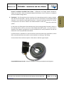
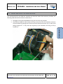
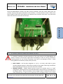
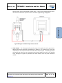
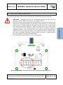
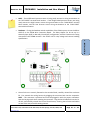
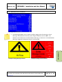
Revision: 2.0 FDPM-MKII Installation and User Manual NOTE – If one Differential pressure sensor is being used, connect its wiring terminations to the “DIFF PRESS” terminal block location. If two Single Ended pressure sensors are being used, connect the High Pressure sensor wiring terminations to the “HIGH PRESS” terminal block location, and the Low Pressure sensor wiring terminations to the “LOW PRESS” terminal block location. Deadman – If using the Deadman switch capabilities of the FDPM system, wire to the RELAY OUTPUT on the FDPM Wire Connection Board. The Relay Output can be set up in a Normally Open (N/O) or Normally Closed (N/C) configuration, with the Common wire being connected to the COMM terminal. See Section 1.9 for relay voltage and current handling specifications. 2 ‐ INSTALLATION Once all wires are securely fastened to the terminal block, carefully reinstall the enclosure lid. First reattach the wiring harness by plugging the connector back into the receptacle. NOTE – This connector is polarized and must be plugged in with the proper orientation. Note the keying notch when reseating the connector. Plug the Serial Cable back into the RJ‐ 45 Jack, and carefully reinstall the lid and Touch Screen, ensuring that all wires and cables are out of the way of the lids seating channel. Velcon Filters LLC, 1210 Garden of the Gods Road, Colorado Springs, Colorado, 80907, USA www.velcon.com Page 21 of 48