1
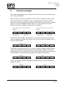
6 Control example This simple example shows how to control the inverter to start the connected motor with a set-point of 50 Hz. After startup and a correct configuration of the inverter and control system, cyclical data are exchanged on the fieldbus, 4 bytes in each direction. The control system sends zeros in both the control word and as set-point value and the inverter responds with the status word 0x0200 and actual value 0. “1” in bit 9 of the status word indicates that input is receptive to control from the fieldbus. Output (from the control system to the inverter) 1 2 3 4 00 00 00 00 MSB LSB MSB LSB Control word Set point Input (from the inverter to the control system) 1 2 3 4 02 00 00 00 MSB LSB MSB LSB Status word Actual value The control system accepts by setting bit 1, 2 and 10 of the control word and the inverter responses by setting bit 0, 4 and 5 of the status word, thus showing that it is ready to start the motor. Output 04 06 Input 00 00 02 31 00 00 The control system now sets bit 0, 3, 4, 5 and 6 and enter set-point as 0x1FFF (8191) which represents 50% of the programmed maximal frequency, 100Hz. The inverter responds to set bit 1 and 2 of the status word. This starts the motor and accelerates it towards 50Hz in accordance with the programmed acceleration parameter. Output 04 7F 1F FF 02 Input 37 00 00 When the motor has reached the programmed frequency, bit 10 in the status word will get the value ”1”. Output 04 NFO Drives AB 2008 7F Input 1F FF 06 37 1F FF Version 1.1 Page 13