1
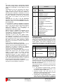
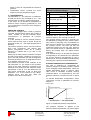
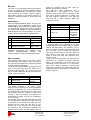
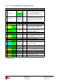
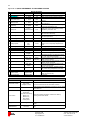
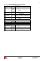
4 The upper circuit board is galvanically isolated from the incoming phases. All signal and control cables are connected to screw clamps on this board. Terminals 21 to 24 are connected to the alarm relay. They are fully isolated from all other voltages within the drive, and are capable of switching 8A at 250VAC. Terminals 21 and 24 are connected by the relay when the drive is free of faults. Terminals 21 and 22 are connected when there is an alarm or the drive is not powered. Terminals M+, M- and 0 are the MODBUS terminals. M+ corresponds to MODBUS D1 or B, while M- is D0 or A. 0 is the MODBUS common ground potential. A 10V reference voltage is available on terminal 1. Terminal 2 is the 0-10V frequency reference input. It can also be used to connect an external active temperature sensor. When used as a frequency reference, the frequency is proportional to the input voltage. Signal common is available on terminals 3,8,10 and 12. Signal common is for EMC reasons connected to protective earth through a 40nF capacitor and a 100kohm resistor. Terminals 4 and 6 are 24V digital inputs. Connecting 24V to terminal 4 makes the motor run forwards. Connecting 24V to terminal 6 either makes the motor run in reverse, or makes the motor run at a fixed frequency. Which depends on the setting of "System settings/Use fixed freq.". A 24V output is available on terminal 5. Terminal 7 is a 0-10V analog input which can be used to connect an external pressure sensor. Terminal 9 is used to connect an external passive NTC thermistor. It can also be used to connect an optional PT1000 adapter. Terminal 11 is a 4-20mA output, which may be loaded with 0-750 ohms. The function of the output is chosen with the setting "System settings/4-20mA output". The choices are measured pressure or motor frequency. The values are scaled such that the maximum value of the signal corresponds to 20mA and zero to 4mA. If the internal pressure sensor is used, the pressure range of the output is 0-1000Pa. If you wish to customize the function of these terminals, do not hesitate to contact us. FRABIL FRACON GRUPPEN Frabil El AB Bjurögatan 38 211 24 Malmö Terminal Nr 21 24 22 M+ M0 1 2 3 4 5 6 7 8 9 10 11 12 Function Alarm Common Alarm OK Alarm Fault MODBUS+ (B or D1) MODBUS- (A or D0) MODBUS Common 10V Reference 0-10V IN 1 (frequency/external active temperature sensor) Signal common 24V Digital In 1 (forward) 24V Output 24V Digital In 2 (reverse/fixed frequency) 0-10V IN 2 (external pressure sensor) Signal common External passive NTC/PT1000 temperature sensor Signal common 4-20mA OUT Signal common DRIVE SETTINGS The FKP has several presets built in which make setting up a drive both faster and safer. A preset is a group of values for all the parameters in the menu system. They allow configuring all the parameters of the drive in a few seconds. Not all presets may be available in all types of the drive. DRIVE SETTINGS: Nr: Parameter: 18 Preset setting 36 Control method Value: Custom, 50Hz Standard, 50Hz Fan 0 - 10V ref, Pressurecont., Tempcomp Pr.cont, Temp. contr Note: When chosen, these presets change all the settings of the drive, including those of the pressure controller. As soon as any parameter in the menu system is changed, the chosen preset will return to "Custom". The way the drive is controlled is selected with parameter 36. There are four ways the FKP can be controlled: 0 - 10V frequency reference input. The FKP is controlled by a voltage on terminal 2, like an ordinary variable speed drive. Pressure control. The FKP will use an external or internal pressure sensor to control pressure with its output frequency. Temperature compensated pressure control. This has the same function as pressure control, with the exception that a temperature Telefon: 040-28 70 90 Fax: 040-18 47 09 www.frabil.se