1
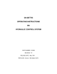
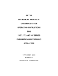
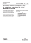
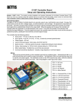
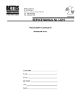
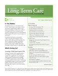
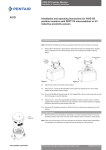
TorqPlus EM Motor Brake Kit
Installation and Operating Instructions
Bulletin: 21078- 09/01. This bulletin provides installation and operating information for the TorqPlus EM Motor Brake Kit. Should you have
any questions about the controller that are not covered under this bulletin, please contact an authorized Bettis Valve Automation Center or
Bettis Electric Division, Mansfield, Ohio U.S.A., 419-529-4296.
1.0
Caution
Electrical shock and/or explosion hazard may exist. To avoid serious personal injury, death, or property damage due to electrical shock and/or ignition of hazardous atmospheres, turn off all power to the actuator before
removing the actuator cover.
2.0
Kit number and model usage
#1420-02
115 Vac for 300/520 series
#15400-02
115 Vac for 500 series
#15800-02
115 Vac for 800 series
#1420-03
230 Vac for 300/520 series
#15400-03
230 Vac for 500 series
#15800-03
230 Vac for 800 series
#1420-10
12 Vdc for 300/520 series
#15400-10
12 Vdc for 500 series
#15800-10
12 Vdc for 800 series
#1420-11
24 Vdc for 300/520 series
#15400-11
24 Vdc for 500 series
#15800-11
24 Vdc for 800 series
3.0
Inspection
Because this optional product is being supplied as a kit, review of the actuator’s nameplate and the kit utilization information is recommended to insure compatibility before use.
4.0
Documentation
Bettis maintains accurate records on every actuator sold. Completion and transmittal of a Product Modification Report (form #ESO-01) is required.
5.0
Cover Removal
Follow section 7.0 in Bulletin #21077 (TorqPlus EM Series Installation and Operating Instructions) supplied
with the actuator.
TorqPlus EM Motor Brake Kit
Installation and Operating Instructions
300 Series, AC Brake Assembly
6.0
Installation Instructions
300 Series, AC Actuator (reference photo above)
Ø Place the brake bracket over the motor shaft and secure using four (4) #6-32 x 3/8 pan head machine
screws with lockwashers.
Ø Place brake onto the bracket and loosely secure using three (3) #4-40 x 7/8 pan head machine screws.
Ø Insert feeler gauges (0.010 to 0.012 in.) between the brake and the bracket.
Ø Place the brake hub onto the motor shaft with the square portion of the hub inserted tightly into the square
of the brake disk.
Ø Secure the brake hub by tightening the set screws.
Ø Remove the feeler gauges and tighten the #4-40 screws on the brake.
Ø Remove the two motor leads from the capacitor.
Ø Place a “Y” connector on the two empty capacitor terminals and reinstall the motor leads to the proper
terminals.
Ø Install the two leads from the brake to the remaining open terminals of the “Y” connector.
300 Series, DC Brake Assembly
2
TorqPlus EM Motor Brake Kit
Installation and Operating Instructions
300 Series, DC Actuator (reference photo bottom page 2)
Ø Place the brake bracket over the motor shaft and secure using two (2) #2-56 x 3/16 flat head machine
screws.
Ø Place brake onto the bracket and loosely secure using three (3) #4-40 x 7/8 pan head machine screws.
Ø Insert feeler gauges (0.010 to 0.012 in.) between the brake and the bracket.
Ø Place the brake hub onto the motor shaft with the square portion of the hub inserted tightly into the square
of the brake disk.
Ø Secure the brake hub by tightening the set screws.
Ø Remove the feeler gauges and tighten the #4-40 screws on the brake.
Ø Remove the existing three terminal push nut and replace it with a five terminal push nut.
Ø Install the two leads from the brake, one lead placed into the five terminal push nut and the other lead
inserted into terminal 1 on the actuator side.
500/800 Series, AC brake assembly
500/800 Series, AC brake assembly (reference photo above)
Ø Place the brake onto the motor and loosely secure using three (3) #4-40 x 1 pan head machine screws.
Ø Place the brake hub onto the motor shaft with the square portion of the hub inserted tightly into the
square of the brake disk.
Ø Raise the brake and hub approximately 1/64 inch. (Feeler gauges cannot be used if top of motor is
counterbored.)
Ø Secure the brake hub by tightening the set screws.
Ø Tighten the #4-40 screws on the brake.
Ø Remove the two motor leads from the capacitor.
Ø Place a “Y” connector on the two empty capacitor terminals and reinstall the motor leads to the proper
terminals.
Ø Install the two leads from the brake to the remaining open terminals of the “Y” connector.
3
TorqPlus EM Motor Brake Kit
Installation and Operating Instructions
500/800 Series, DC brake assembly
500 Series, DC Actuator (reference photo above)
Ø Place brake onto the motor and loosely secure using three (3) #4-40 x 1 pan head machine screws.
Ø Insert feeler gauges (0.010 to 0.012 in.) between the brake and the bracket.
Ø Place the brake hub onto the motor shaft with the square portion of the hub inserted tightly into the square
of the brake disk.
Ø Secure the brake hub by tightening the set screws.
Ø Remove the feeler gauges and tighten the #4-40 screws on the brake.
Ø Remove the existing three terminal push nut and replace it with a five terminal push nut.
Ø Install the two leads from the brake, one lead placed into the five terminal push nut and the other lead
inserted into terminal 1 on the actuator side.
7.0
Wiring Instructions
Installation of the kits shall be performed to the proper wiring diagrams. In most cases, the diagram will be WD0001 for the AC units and WD-0004 for the DC units. Route all wiring carefully so not to make contact with
moving parts and secure with wire ties. Wiring and conduit connections must be made in accordance with local
and national codes and consistent with good practices.
8.0
Cover Replacement
Follow section 9.0 in Bulletin #21077 (TorqPlus EM Series Installation and Operating Instructions) supplied with
the actuator.
4