1
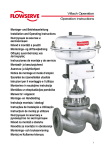
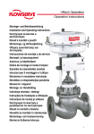
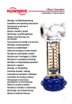
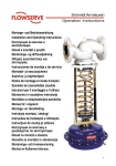
Montage- und Betriebsanleitung
Installation and Operating Instructions
Инструкция за монтаж и
експлоатация
Návod k montáži a použití
Monterings- og driftsvejledning
Οδηγίες εγκατάστασης και
λειτουργίας
Instrucciones de montaje y de servicio
Montaaži- ja kasutusjuhend
Asennus- ja käyttöohjeet
Notice de montage et mode d’emploi
Szerelési és üzemeltetési utasítás
Istruzioni per il montaggio e l’utilizzo
Montavimo ir naudojimo instrukcija
Montāžas un ekspluatācijas pamācība
Manwal ta’ l-Apparat
Montage- en Handleiding
Instrukcja montażu i obsługi
Instruções de Instalação e Utilização
Instrucţiuni de montaj şi utilizare
Инструкция по монтажу и
руководство по эксплуатации
Návod na montáž a obsluhu
Navodila za montažo in obratovanje
Monterings- och bruksanvisning
Montaj ve Kullanma kılavuzu
Montage- und Betriebsanleitung
Installation and Operating Instructions
Инструкция за монтаж и експлоатация
Návod k montáži a obsluze
Monterings- og driftsvejledning
Page 15 - 24
страница 25 - 34
Strana 35 - 44
Side 45 - 54
Οδηγίες εγκατάστασης και λειτουργίας
Σελίδα 55 - 64
Instrucciones de montaje y de servicio
Página 65 - 74
Montaaži- ja kasutusjuhend
Asennus- ja käyttöohjeet
Lehekülg 75 - 84
Sivu 85 - 94
Notice de montage et mode d’emploi
Pages 95 à 104
Szerelési és üzemeltetési utasítás
105 - 114. oldal
Istruzioni per il montaggio e l’utilizzo
Montavimo ir naudojimo instrukcija
Montāžas un ekspluatācijas pamācība
Manwal ta’ l-Apparat
Pagina 115 - 124
p. 125 – 134
135. – 144. lappuse
Paġni 145 - 154
Montage- en Handleiding
Pagina 155 - 164
Instrukcja montażu i obsługi
Strona 165 - 174
Instruções de Instalação e Utilização
Instrucţiuni de montaj şi utilizare
DE
EN
BG
CS
DA
EL
ES
ET
FI
FR
HU
IT
LT
LV
MT
NL
PL
PT
RO
RU
SK
SL
SV
TR
Seite 5 - 14
Páginas 175 - 184
Paginile 185-194
Инструкция по монтажу и руководство по эксплуатации стр. 195 - 204
Návod na montáž a obsluhu
Strana 205 - 214
Navodila za montažo in obratovanje
Stran 215 - 224
Monterings- och bruksanvisning
Sidan 225 - 234
Montaj ve Kullanma Kılavuzu
Sayfa 235 - 244
Contents
Preface
Scope
Product description
1.
1.1
1.1.1
1.1.2
1.2
1.3
2.
3.
4.
4.1
Installation
“As delivered” status
Transport
Storage
Preparation for installation into the piping
Rating plate
Installation of the control valve
Recommended installation
Commissioning
Flange connection
Welded connection
Maintenance
Repair
Troubleshooting, service and repair centres
Page
EN
15
16
16
16
17
17
17
17
18
18 + 19
19
20
20
21
22
22
23 + 24
This control valve was manufactured to the strict standards of our ISO 9001 certified quality
management system. It was tested for compliance with all applicable regulations and
guidelines and fully conforms with all contractually agreed specifications.
To ensure a faultless and reliable operation of this product, please read and observe these
installation and operating instructions before using this product.
Failure to comply with these installation and operating instructions will render the manufacturer’s
guarantee and liability null and void. Unless otherwise agreed, the manufacturer’s General
Terms and Conditions of Sale shall apply.
15
EN
Scope
These operating instructions shall apply to:
•
•
•
•
•
with fitted pneumatic or electrical linear actuator
with fitted linear unit and electrical rotary actuator
• with or without accessories
Product description
Control valves control gases, vapours or liquids and change the
flow conditions of a process.
The control valves consists of the body (valve bottom) and the
actuator which, depending on the control signal, changes the
position of the closure member (plug) relative to the seat. The
bodies have been arranged in logical kits, allowing the user
to assemble the highest possible number of variants from a
minimum of components to match each individual application.
Our range also includes a series of peripheral units such as
positioners, boosters, filter-reducing stations or solenoid valves.
Positioners and solenoid valves can be assembled directly or
according to NAMUR recommendations. Refer to the relevant
manufacturer’s instruction manual for information regarding
peripheral equipment.
Single-seated control valves (PN 10–160, Class 150–900)
Lined single-seated control valves (PN 10/40)
Three-way control valves (PN 10–160, Class 150–600)
Double-seated control valves (PN 10–160)
Special valves
1. Installation
16
The valve must be installed and commissioned by
qualified staff. Qualified staff is defined as personnel
who are familiar with the installation, commissioning
and operation of this product and possess the relevant
qualifications in their field of activity.
1.1 “As delivered” status
Control valves are generally delivered as tested and
assembled units with the actuators fitted. Parts of the
body and actuator subject to corrosion are protected by a coat of
paint. Unpainted components are greased and the openings of
the housings are closed with plugs. High-grade steel housings are
delivered without a protective coat of paint (pickled or blasted).
1.1.1 Transport
Careful loading and transport arrangements are required to
avoid the product suffering impact and jolting movements.
Under no circumstances should lifting gear be attached to
the valve spindle, travel indicator and any peripheral units, if
applicable. We recommend the use of a length of rope that
is looped around the valve head underneath the yoke (or the
transportation eyelet(s)). The maximum permitted carrying
capacity must be observed. Promptly touch up any damage to
the corrosion protection.
1.1.2 Storage
Upon arrival on site, store the control valve on a solid base in a
closed room. Until its installation, the valve must be protected
from the weather, dirt and other potentially harmful influences.
Under no circumstances should the valve remain in storage for
more than 6 months, as the impregnation in the stuffing box
packing evaporates and leaks may develop. Do not remove the
plugs protecting the flanges and the inside of the control valve
until it has arrived at its place of installation.
1.2 Preparation for installation into the piping
The pressure, leak and operation tests performed in the
factory and the quality management system introduced by the
manufacturer ensure that the execution of the control valve
complies with the specifications set forth in the contract The
series number and the vital valve actuator data are found on
the rating plate. The travel indicator shows the position of the
closure member relative to the seat.
Before installing the valve, carefully clean the piping.
17
EN
Rating plate
EN
As the information on rating plates reflects the special features of the type they describe, their appearance may differ. The rating
plate contains the following data:
Kennzeichnung / Tag No.
Typ / Type
DN / PN
Sitz ø / Seat ø
Kvs / Cv
Kegel / Plug
Kennlinie / Characteristic
Mat. Gehäuse / Mat. Body
Innenteile / Trim
Packung / Packing
Betriebsdruck / Working Pressure
Fabrikations Nr. / Serial No.
Antrieb Typ / Actuator Type
Hub / Stroke
Zuluft min. max. / Supply min. max.
Federlaufbereich / Spring Range
Sicherheitsstellung / Failure Position
Umgegungstemp. / Ambient Temp.
∆p Antrieb / ∆p Actuator
Einbaulage / Arrangement
Betriebstemperatur / Working Temperature
1.3 Before installation, check the following items:
• The operator is required to carefully check the suitability of the
control valve for its intended use in the system in advance.
Any use not in compliance with the regulations/specifications can lead to serious
damage to the control valve or may lead to failure of the facility!
• Does the nominal/operation data on the rating plate match
the operational data of the facility?
A mismatch may cause considerable damage to the valves.
• At the point of installation, is there enough space to fit and
remove the valve?
A lack of space can cause considerable problems and in the some cases
necessitate expensive rerouting of the piping!
• Was the piping flushed and cleaned prior to the installation?
Foreign particles can damage the control valve and accessories; this can be
avoided by fitting a suitable dirt trap.
• Was the protective coat removed from the control valve, and
was the valve cleaned?
The preservative (Mipa Abziehhaut blue) and the spray (Castrol Safecoat
DW 32) can contaminate the operating medium and must be removed before
installation.
Unsuitable cleaning agents that attack the PTFE and graphite sealing sets
can cause damage and leaks. Pay particular attention to the relevant chemical
resistance lists.
Remove covers.
• Does the direction of flow arrow on the housing coincide with
the direction of flow of the medium?
If not, critical operating conditions can result that may damage the control valve,
as they are not designed to cope with this situation.
18
• Are the piping flanges equiaxial and parallel and does the
distance between pipe ends correspond to the valve length?
If not, excessive tension, valve malfunctions and leaks at the flange connections
may result.
• Is the piping routed correctly and is the valve free from
additional piping forces?
If not, leaks may develop and, depending on the situation, the valve may fail.
• Is the installation position of the valve with vertical valve
spindle achieved?
If not, increased wear in the stuffing box packing, leaks and, depending on the
situation, rubbing may occur.
Contact the manufacturer if the prevailing installation conditions mean that the
valve will have to be fitted horizontally.
• Is there a suitable surge section upstream and downstream
of where the valve is installed?
The absence of a surge section can create critical operating conditions and
cause impermissible levels of noise and vibration!
• Is appropriate equipotential bonding provided?
Impermissible electrical compensating currents across the valve and the actuator
can generate static and cause electrical discharging.
In explosive atmospheres, the only valves that may be used
are those that comply with the permitted group, equipment
category and temperature class requirements laid down in
Directive 94/9/EC (ATEX)!
Recommended installation Successful use of the control valve is conditional on
the availability of a suitable installation environment.
We suggest that the recommended values be adhered to, as it is very important to take
account of physical aspects when using the control valve. Deviations can result in significant
control deviations, and in the worst case expensive rerouting of the piping will be necessary.
However, some physical processes will permit a deviation from these values, although in such
cases system knowledge is required, as is the express approval of the manufacturer.
Recommended installation for
control valves
Control valve
Dirt trap
(0.1 mm)
Medium
Installation distance from valve 10 x DN
(at least 1m)
19
EN
2. Commissioning
The medium and the valve can pose the following hazards:
• Critical operating conditions can cause impermissible levels
of noise and vibration.
EN
Hearing loss, vascular and nerve problems, damage to joints and bones!
• Incorrect maintenance can result in the emission of thermal,
cryogenic and toxic operating media.
Danger of burns, freezing, acid burns, poisoning!
• The temperature of the operating medium is transferred to the
surface of the valve.
Danger of burns, freezing, explosion!
As these hazards can all be controlled by the plant operator,
the operator is obliged to comply with national and international
environmental regulations, install suitable protective measures
to ensure workplace requirements are satisfied, and to instruct
his employees accordingly.
Due to the risk of injury, it is prohibited to work between
the yoke/columns while the valve is in operation.
Once these hazards have been averted by adopting appropriate
protective measures, the valve can be installed and connected
in the piping. The following points should be noted:
• Flange connection:
Connection material (gaskets, bolts, nuts) are not part of the
scope of supply.
Locate gaskets in the centre of flanges, failure to do so can result in leaks and
increased noise levels.
If a completely installed piping is to be flushed or blown through for cleaning,
replace the control valve with a matching piece.
• Welded connection:
Welded connections have to be made in compliance with
applicable welding regulations.
After welding, carefully clean the piping again. Open control valves properly and
remove any accumulated foreign particles. Advise the manufacturer in writing
that the fitting has been opened!
20
When the control valve is installed in the piping:
• connect instrument air to the actuator or installed accessories
(applies to pneumatic linear actuators).
• connect according to the wiring diagram in the removable
actuator cover or according to manufacturer’s actuator
documentation (applies to electrical rotary/linear actuators).
• Continuously increase load until operation parameters are
reached.
Sudden exposure of the control valve to the full working pressure and working
temperature may cause stress cracks.
• After the first loading (trial run) in depressurised and cool
conditions, evenly tighten screw connections of sealing
components crosswise (if required).
Be careful to prevent damage to the high quality spindle surface finish! A
damaged spindle surface finish may be detrimental to the smooth operation of
the stuffing box.
• Excessive levels of noise and vibration during operation
indicate critical operating conditions and must be avoided at
all costs.
Impermissible continuous operation of control valves under critical conditions
can damage the valves, as they are not designed to cope with this situation.
• Avoid frequent system start-ups and shutdowns.
Experience has shown that critical operating conditions, which can damage
the control valve, are often encountered when starting up or shutting down the
system.
• Keep the operating medium free of foreign particles.
Foreign particles can damage the control valve; this can be prevented by fitting a
suitable dirt trap.
• The instrument air must conform to at least the ISO 8573-1
class 2 or the requirements of the accessory manufacturer.
Contaminated instrument air can damage the accessories and valve or cause
them to fail.
Bodily injury or damage to the control valve and its accessories as the result of nonadherence to warning instructions, as well as transport damage and improper use
(e.g. as a climbing aid, etc.), will render the manufacturer’s guarantee null and void
and release him from any responsibility.
21
EN
3. Maintenance
EN
Measure
Interval
Clean valve and actuator spindle with
a soft cloth
Tighten if stuffing box leaks
Caution:
Do not „over seal“
the stuffing box!
depending on degree of contamination
Standard stuffing boxes subjected to
“normal“ operating conditions
every 10,000 strokes
Standard stuffing boxes subjected to “difficult“ operating conditions
• packing exposed to aggressive medium
• major temperature change during operation
• occurrence of vibrations
• unfavourable installation position
Check spring tension and tighten if
necessary
every 5,000 strokes
Spring loaded stuffing box systems and
“normal“ operating conditions
every 100,000 strokes
at least once per year
Spring loaded stuffing box systems and
“difficult“ operating conditions
every 10,000 strokes
Pneumatic linear actuators
maintenance free
Electric linear/rotary actuators
Check spindle/gear
if required, lubricate
Electric linear/rotary actuators
Grease (grease nipple)
4. Repair
largely maintenance free
every 200,000 up-and-down strokes
at least once per year
If a fault or defect occurs which, according to the list of measures
below, requires the customer services department or contract
partner to be contacted, the manufacturer’s guarantee shall be
rendered null and void - and the manufacturer released from
any responsibility - unless the customer services department
or contract partner is duly notified. If the customer performs the
repairs himself, these operating instructions and the respective
disassembly/assembly instructions must be followed to the letter
and carried out in a competent manner. Original replacement
parts must be used in every case.
Control valves are pressure vessels!
Improper opening of the actuator or fitting may result
in bodily injury!
22
4.1 Trouble shooting
Defect
Spindle does not move
No. Possible causes
1.1
• no aux. energy supply (pneumatic
air or electrical power) to actuator
and
accessories
(solenoid
valve, filter-reducing station,
positioner, limit switch and special
accessories)
• pneumatic actuators: check supply line for leaks
check pressure (usually 6 bar)
• electrical actuators: check power supply
(connections, circuit breakers, voltage)
1.2
• the fitted accessories do not work
• see maintenance and operating instructions of
accessories manufacturer
1.3
• the pneumatic
defective
is
• contact customer services department or
contract partner
1.4
• the electrical actuator is defective
• see maintenance and operating instructions of
actuator manufacturer
1.5
• excessive tightening of the stuffing
box packing
• loosen stuffing box packing nuts until valve
operates properly
actuator
Caution:
Jolting spindle movement
Spindle travel less than full stroke
(0 to 100% stroke)
or flow rate is too low
EN
Remedy
make sure there are no leaks!
1.6
• valve trim worn, stuck
• contact customer services department or
contract partner
2.1
• the electrical actuator is defective
• clean spindle with suitable cleaning agent
2.2
• damaged spindle
• contact customer services department or
contract partner
2.3
• actuator not powerful enough
• compare actuator specs on the rating plate
with operation specifications of the facility
- if incompatible, contact customer services
department or contract partner
3.1
• air supply pressure too low
• provide air at the pressure stated on the rating
plate
3.2
• pneumatic actuators: bad hand
wheel position (hand wheel
emergency operation)
• move hand wheel to limit position
3.3
• electrical actuators: limit switch
misadjusted
• readjust limit switch to actuator manufacturer‘s
specification
3.4
• badly adjusted
positioner
defective
• readjust positioner to positioner manufacturer‘s
specifications
3.5
• foreign particles in valve seat,
damaged trim
• contact customer services department or
contract partner
or
23
Trouble shooting - continued
EN
Defect
No. Possible causes
Remedy
Excessive valve-seat leakage
4.1
• damaged sealing edges at valve
seat or plug
• contact customer services department or
contract partner
4.2
• foreign particles in seat area
• contact customer services department or
contract partner
4.3
• plug does not close fully
• refer to 3.1 to 3.5
5.1
• compression force on packing too
low
• slightly re-tighten stuffing box packing
• worn packing
• slightly re-tighten stuffing box packing
Leaking stuffing box system
5.2
Caution:
Caution:
make sure the valve spindle
can still move!
make sure the valve spindle
can still move!
if the packing does not stop leaking, contact
customer services department or contract
partner
5.3
• dirty spindle
• clean spindle with suitable cleaning agent
5.4
• damaged spindle
• contact customer services department or
contract partner
6.1
• pressing force on seal(s) too low
• properly re-tighten top or lid nuts crosswise
6.2
• seals(s) defective
• contact customer services department or
contract partner
Leaking housing
7.1
• medium- or flow-related damage
• contact customer services department or
contract partner
No limit switch signal
8.1
• power supply to limit switch
interrupted
• check power supply (connections, circuit
breakers, voltage)
8.2
• limit switch misadjusted
• readjust limit switch; operating distance see
limit switch data sheet
9.1
• defective positioner
• see maintenance and operating instructions of
positioner manufacturer
Leaking top or lid seal
Vibrating positioner
If the problem is not solved by taking the above measures, contact the customer services
department or contract partner.
Service hotline Austria:
Service hotline Germany:
+43 (0)664 341 8 616
+49 (0)2157-8176-29 or +49 (0)163-8176-014
24
245
246
EG Konformitätserklärung / EC Declaration of Conformity
gemäß DGRL 97/23/EG / acc. to PED 97/23/EC
gemäß Richtlinie 90/396/EWG / acc. to Directive 90/396/EEC
gemäß ATEX 94/9/EG / acc. to ATEX 94/9/EC
gemäß Richtlinie 2006/42/EG / acc. to Directive 2006/42/EC
Hersteller/Manufacturer
Richtl./Dir.
2006/42/EG
EN 161,
DIN 3394
EN 264
DIN 32725
SIL
IEC 61508
ISO 15848
VDI 2440
Autom. Absperrarmaturen für gasförmige Brennstoffe u.
Sicherheitsabsperreinrichtungen für flüssige Brennstoffe
Automatic shut-off valves for inflammable gases and
Safety shutoff devices for inflammable liquids
Type D726, D738, D740
Stellgeräte FlowTop
Control valves FlowTop
Type V726, V738, V740
Stellgeräte / Control valves
Type V724, V760
Stellgeräte / Control valves
Type V725, V723
Stellgeräte / Control valves
Type MarkOne, Mark100, MarkSix
Stellgeräte / Control valves
Sonderregelventile / Special control valves 1)
Einspritzkühlventile
Injection nozzle valves Type V901
Selbsttätige Regler
Self acting regulators Type 5801, 5610
Pneumatische Antriebe / Pneumatic actuators
Type FlowAct, Valtek Piston Actuator
ATEX
94/9/EG
Produkte / Products
Richtl./Dir.
90/396/EWG
Richtlinien / Directives
DGRL/PED
97/23/EG
Mod.
FLOWSERVE (Austria) GmbH
Control Valves – Villach Operation
Kasernengasse 6, A-9500 Villach
B+D
●
●
●
●
●
●
●
B+D
H
●
●
●
●
●
●
H
●
●
●
●
H
●
●
H
●
●
●
H
●
●
●
H
●
H
-
●
●
●
1) Für den Europäischen Markt / for European Market
Benannte Stelle für die Kontrollen / Notified Body for the Inspections
DGRL 97/23/EG / PED 97/23/EC
TÜV CERT-Zertifizierungsstelle für Druckgeräte der TÜV Anlagentechnik GmbH
Am Grauen Stein, D-51101 Köln
Kennummer der Benannten Stelle /
Number of Notified Body
0035
Richtlinie 90/396/EWG / Directive 90/396/EEC
DVGW Zertifizierungsstelle Technisch-wissenschaftlicher Verein
Josef-Wirmer-Straße 1-3, D-53123 Bonn
Kennummer der Benannten Stelle /
Number of Notified Body
0085
Management - System / Management - System OHSAS 18001:2007, ISO 14001:2004, ISO9001:2008
DNV Zertifizierung und Umweltgutachter GmbH
Schnieringshof 14, D-45329 Essen
Bevollmächtigter des Herstellers in der EG
Authorized representatives of the manufacturer in the EC
Villach, 09.11.2009
Dipl.-Ing. Arnold Muschet
Technischer Leiter / Technical Director
Ing. Herbert Schifferl
QM Leiter / QM Manager
247
TM
Indicates a trade mark of Schmidt Armaturen.
Information given in this leaflet is made in god faith and based upon specific testing but does not, however, constitute a guarante.
Modifications without notice in line with technical progress
OI 133414 11/09 Control Valves eu
�����������������
Flowserve (Austria) GmbH
Control Valves - Villach Operation
Kasernengasse 6
A-9500 Villach
Telephone:+43 (0) 4242 41181-0
Facsimile: +43 (0) 4242 41181-50 or 51
e-mail:
[email protected]
www.flowserve.com
248
SAEUOIVALV-04 11.09