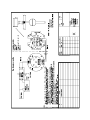
1
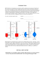
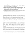
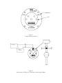
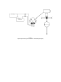
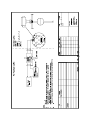
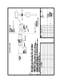
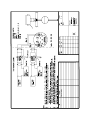
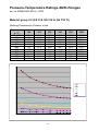
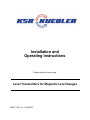
Installation and
Operating Instructions
Please retain for future usage
Level Transmitters for Magnetic Level Gauges
120872 / Rev. 01 - 22.04.2015
INTRODUCTION
KSR Kuebler level transmitters are primarily used for continuous measurement of liquid levels.
They operate by using the field of a magnet inside the float to actuate reed switches inside the
device rod. A measuring network (reed switches and precision resistors) built into the transmitter
rod provides an internal potentiometer-style signal proportional to the position of the float. The
resolution of the transmitter is dependent on the number of switches per unit length and is
customer specified along with device length at the time of order. The output of the device is twowire 4 to 20 ma and can be configured to increase or decrease with float level.
For your convenience please enter:
Model # ______________________
Serial # ______________________
KSR Kuebler level transmitters have approvals up to Explosion Proof Class 1, Division 1, Group
B depending on the ordered configuration. They can be used for Intrinsically Safe applications up
to Group A with the addition of an agency approved safety barrier. All materials which come into
contact with the liquid must be corrosion resistant and are customer specified. The liquid to be
monitored must not be heavily contaminated and must not have a tendency to crystallize or
solidify.
INSTALLATION NOTES!
• KSR
Kuebler level transmitters must be installed within 30 degrees of vertical to function
correctly. They must not be installed within 3 feet of strong electromagnetic fields.
•
When installing a level transmitter in a vessel connection smaller than the diameter of
the float requiring removal of the float(s), mark the top of the float(s) and the position
of the retaining collar(s). Be sure to replace the float(s) in the same orientation.
Reposition and securely tighten the retaining collar(s).
•
All wiring and hardware must be in accordance with applicable standards and
regulations. Avoid running 4 to 20 ma cabling next to AC power wiring, always use
shielded cable. When installing in a location requiring Intrinsic Safety, an agency
approved barrier must be used (see Installation Drawings).
•
Install a pour-seal fitting within 18 inches of the housing to prevent water from entering
the housing and for compliance with the National Electrical Code.
INSTALLATION
(Transmitters with Integral Electronics)
Install KSR level transmitters according to their type (flange, thread, or bracket) using the correct
gasket or compound for sealing. Make sure the gasket is installed correctly and tighten all fasteners
to the correct torque. Replace the float(s) and retaining collar(s) in the correct orientation if
previously removed. Note it may be easier to calibrate the unit before installation if possible.
Transmitters with integral electronics (puck and/or display) must be connected in a series loop
with the readout or data acquisition device and the power supply. Shielded cable must be used for
noise immunity and for Intrinsically Safe applications an agency approved safety barrier must be
installed. A ground wire must be provided and connected to the ground block inside the housing.
To connect a transmitter with a built-in digital display, unscrew and remove the housing cover and
carefully remove the plastic label from around the display by grasping each side and pulling
upwards. Remove the digital display by carefully pulling up on two diagonal sides of the display.
The indicator is held in place by two banana plugs which plug into the baseboard where the 4 to 20
ma puck is mounted. Field wiring connections are made to a two point, compression type,
terminal block located on the baseboard (see Fig. 2 for Explosion Proof or drawing 095-3201-001
Pg. 1 for Intrinsically Safe applications). Attach a ground wire directly to the ground screw inside
the housing.
To connect a transmitter without a built-in display, unscrew and remove the housing cover. Field
wiring connections are made directly to the puck (see Fig 3 for Explosion Proof, drawing 0953201-001 Pg. 2 for single puck Intrinsically Safe applications, or drawing 095-3201-001 Pg. 4 for
dual puck Intrinsically Safe applications). Attach a ground wire directly to the ground screw inside
the housing.
The transmitter comes pre-wired from the factory, however to reverse the reading of the gauge
relative to the float position it is necessary to reverse the “max” and “min” connections on the
puck (see Figure 1).
4 to 20
LOOP
+
Base Board
ZERO
SPAN
PS PS +
ARM
MAX
MIN
Puck
Figure 1
Component Identification
+
-
+
+
Display or
control device
4 to 20
LOOP
SPAN
ZERO
PS PS +
ARM
MAX
MIN
Power Supply
Figure 2
Explosionproof Wiring for Transmitters with Integral Display
+
-
+
Display or
control device
PS PS +
ARM
MAX
MIN
Power Supply
Figure 3
Explosionproof Wiring for Transmitters without Integral Display
≤
≤
≥
≥
K
s r
≤
≤
≥
≥
K
s r
INSTALLATION
(Transmitters with remote electronics)
Install KSR level transmitters according to their type (flange, thread, or bracket) using the correct
gasket or compound for sealing. Make sure the gasket is installed correctly and tighten all fasteners
to the correct torque. Replace the float(s) and retaining collar(s) in the correct orientation if
previously removed.
Transmitters with remote electronics must be connected using three-conductor shielded cable (see
Fig. 4 for Explosion Proof, drawing 095-3201-001 Pg. 3 for single puck Intrinsically Safe
applications, or drawing 095-3201-001 Pg. 5 for dual puck Intrinsically Safe applications).
The symbols screened on the board show the connections to the terminal blocks. By reversing the
“max” and “min” connections at the puck, the gauge readout can be reversed relative to the float
position (see Fig. 1).
Power Supply
+
+
Display or
control device
4 to 20
LOOP
PS PS +
ARM
MAX
MIN
010-0110-XXX Rev: A
ZERO
PRESSURE
SPAN
XMITTER 2
+
RTD
XMITTER 1
K
Figure 4
Explosion Proof Wiring for Transmitters With Remote Electronics
≤
≤
≤
≥
≤
≥
K
K
s r
≤
≤
≤
≥
≤
≥
K
K
s r
QUALIFICATION
WARNING! Make sure any tests performed in qualification do not unintentionally start
any processes resulting in loss of control.
WARNING! Never open cover in hazardous areas while circuits are energized. Follow all
safety work procedures and lock out circuits before servicing or inspection.
To calibrate units with built-in display, two clip leads are required to connect the indicator to the
puck baseboard. Connect the clip leads in the same polarity as the indicator plugs into the
baseboard making sure no shorts circuits are created; note the indicator will only plug into the
baseboard one way. Units with no built-in display do not require jumpers. Power up the device
using a suitable calibration source, insuring no processes will be affected during calibration. Move
the float to the desired 0% position and adjust the zero adjustment potentiometer on the puck
until the display reads 0% or the calibrator indicates 4 ma. Move the float to the desired 100%
position and adjust the span potentiometer on the puck until the display reads 100% or the
calibrator indicates 20 ma. Move the float back and forth several times to check both settings.
The indicator unit is factory calibrated to read 0% to 100% for 4 to 20 ma respectively and can be
calibrated with a suitable supply by adjusting the “zero” and “span” pots of the upper board of the
display unit. The pot on the lower display board should not be adjusted.
Install the indicator unit and replace the plastic label around the display. Screw the cover back on
the display and tighten.
Replace and tighten the housing cover and energize the power supply for the connected control
unit(s). Fill the tank in order to observe that the readout changes smoothly. The level transmitter
can also be tested manually by moving the float by hand and observing the result. The 0% and
100% points should be re-checked to ensure they are set correctly.
MAINTENANCE
KSR Kuebler level transmitters operate free from maintenance and wear when used properly. A
periodic visual inspection and re-qualification test should be performed at a regular interval.
QUESTIONS
For customer support please call 1-888-KSR-LEVL (577-5385) between the hours of 8:00 a.m. and
5:00 p.m. Eastern time. Please have your model number and serial number (found on the device
label) handy.
Pressure-Temperature Ratings ANSI-Flanges
acc. to ASME/ANSI B16.5 - 2003
Material group 2.2 (SS 316, SS 316 H, SS 316 Ti)
Working Pressures by Classes, in bar
Temperature
in °C
-29 to 38
50
100
150
200
250
300
325
350
375
400
150
300
600
900
1500
2500
19,0
18,4
16,2
14,8
13,7
12,1
10,2
9,3
8,4
7,4
6,5
49,6
48,1
42,2
38,5
35,7
33,4
31,6
30,9
30,3
29,9
29,4
99,3
96,2
84,4
77,0
71,3
66,8
63,2
61,8
60,7
59,8
58,9
148,9
144,3
126,6
115,5
107,0
100,1
94,9
92,7
91,0
89,6
88,3
248,2
240,6
211,0
192,5
178,3
166,9
158,1
154,4
151,6
149,4
147,2
413,7
400,9
351,6
320,8
297,2
278,1
263,5
257,4
252,7
249,0
245,3
13
Pressure-Temperature Ratings ANSI-Flanges
acc. to ASME/ANSI B16.5 - 2003
Material group 2.3 (SS 316 L)
Working Pressures by Classes, in bar
Temperature
in °C
-29 to 38
50
100
150
200
250
300
325
350
375
400
150
300
600
900
1500
2500
15,9
15,3
13,3
12,0
11,2
10,5
10,0
9,3
8,4
7,4
6,5
41,4
40,0
34,8
31,4
29,2
27,5
26,1
25,5
25,1
24,8
24,3
82,7
80,0
69,6
62,8
58,3
54,9
52,1
51,0
50,1
49,5
48,6
124,1
120,1
104,4
94,2
87,5
82,4
78,2
76,4
75,2
74,3
72,9
206,8
200,1
173,9
157,0
145,8
137,3
130,3
127,4
125,4
123,8
121,5
344,7
333,5
289,9
261,6
243,0
228,9
217,2
212,3
208,9
206,3
202,5
14
KSR Kuebler Limited Product Warranty
When used in accordance with the applicable documentation, all KSR Kuebler level controls are warranted
free of defects in workmanship or materials to the original end-user as follows from the date of original
factory shipment:
Five (5) full years for Level Switches & Magnetic Level Indicators
Two (2) full years for Level Transmitters
When returned prepaid within the warranty period and upon factory inspection of the unit and verification of
a defect, KSR Kuebler will repair or replace, at its discretion, the defective unit at no cost (other than
transportation). KSR Kuebler shall not be liable for direct or consequential equipment damage due to
corrosion nor any incompatibility of the materials of construction of the equipment with the process and/or
equipment of the user. KSR Kuebler shall not be liable for any type of damage, or loss, direct or
consequential, due to misapplication, mis-specification, misuse, damage due to mechanical or electrical
overloading, improper mounting, or failure of the device. KSR Kuebler shall not be liable for any direct or
consequential damage, expense, or labor claims stemming from the use or installation of KSR Kuebler
equipment. Any unauthorized modification, repair or rework of KSR Kuebler equipment renders this
warranty null and void.
THE WARRANTIES SET FORTH ABOVE ARE EXCLUSIVE AND IN LIEU OF ALL OTHER
WARRANTIES, WHETHER STATUTORY, EXPRESS OR IMPLIED (INCLUDING ALL
WARRANTIES OF MERCHANTABILITY AND FITNESS FOR A PARTICULAR PURPOSE AND
ALL WARRANTIES ARISING FROM COURSE OF DEALING OR USAGE OF TRADE).
KSR Kuebler of America Inc
950 Hall Court
Deer Park, Texas 77536
KSR Kuebler Niveau-Messtechnik AG
Heinrich-Kuebler-Platz 1
69439 Zwingenberg am Neckar
Phone: 713-475-0022
Fax: 713-475-0011
[email protected]
www.ksr-usa.com
Phone: +49 6263 87-0
Fax: +49 6263 87-99
[email protected]
www.ksr-kuebler.com