1
]1
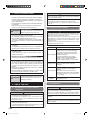
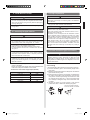
6.9. Drain pump unit (Optional parts)
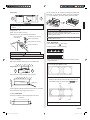
There are 3 methods for address setting by FIELD SETTING
as follows.
Set by either of the methods.
Each setting method is described (1) to (3) below.
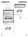
• For the installation method, please refer to the
INSTALLATION MANUAL of drain pump unit.
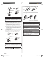
Connection methods
• Connection terminals
Float switch
terminal (CN15)
Controller PCB
7. FIELD SETTING
(1) IU AD, REF AD SW settings..... This section (7.1. Setting
the address)
(2) Remote controller settings ....... Refer to the wired or
wireless remote controller
manual for detailed setting
information. (Set IU AD,
REF AD SW to 0)
(3) Automatic address settings ...... Refer to the outdoor unit
manual for detailed setting
information. (Set IU AD,
REF AD SW to 0)
Drain pump
terminal (CN5)
CAUTION
• Be sure to turn OFF the power before performing the field
setting.
1
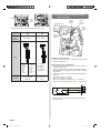
7.1. Setting the address
CAUTION
• Use an insulated screwdriver to set the dip switches.
SW SW SW SW
1 2 3 4
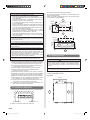
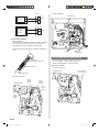
• Wiring arrangement
Dip switch “SET 3”
Controller PCB
Clamp
Rotary switch
Example: “0”
Rotary switch
Example: “0”
Power supply cable
Cable clamp
Binder*
(Bind with the power supply cable.)
Cable clamps
Setting
Setting
range
Indoor unit
address
0–63
Type of switch
Setting
example
2
IU ADX10
IU ADX1
REF ADX10
REF ADX1
Binder*
*Accessories of Drain pump unit
Refrigerant
circuit
address
0–99
Setting
example
63
En-18
9373385110-02_IM_EN.indd 18
2012-8-31 10:40:26