1
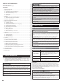
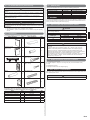
15.ERROR CODES
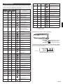
If you use a wireless remote controller, the lamp on the photo detector unit will output error codes by way of blinking patterns. If you use a wired remote controller, error codes will
appear on the remote controller display. See the lamp blinking patterns and error codes in
the table. An error display is displayed only during operation.
Error display
OPERATION TIMER ECONOMY
lamp
lamp
lamp
(green)
(green)
(orange)
Wired
remote
controller
Error code
Description
Current sensor error
Ɣ(8)
Ɣ(4)
¸
Ɣ
Ɣ
(6)
¸
Ɣ(9)
Ɣ(4)
¸
Trip detection
Ɣ(9)
Ɣ(5)
¸
Compressor rotor position
detection error (permanent stop)
(8)
• Discharge pressure sensor
error
• Suction pressure sensor error
• High pressure switch error
Ɣ(1)
Ɣ(1)
¸
Serial communication error
Ɣ(9)
Ɣ(7)
¸
Outdoor unit fan motor error
Ɣ(1)
Ɣ(2)
¸
Wired remote controller
communication error
Ɣ(9)
Ɣ(9)
¸
4-way valve error
Ɣ(1)
Ɣ(5)
¸
Check run un¿nished
Ɣ(10)
Ɣ(1)
¸
Discharge temp. error
Ɣ
Ɣ
Unit number or Refrigerant circuit
address setting error
[Simultaneous Multi]
Ɣ(10)
Ɣ(3)
¸
Compressor temp. error
¸
Ɣ(10)
Ɣ(4)
¸
High pressure error
Ɣ(10)
Ɣ(5)
¸
Low pressure error
Ɣ(13)
Ɣ(2)
¸
Branch boxes error
[Flexible Multi]
(2)
Ɣ(2)
Ɣ(2)
(1)
Ɣ(2)
Ɣ(3)
¸
Indoor unit capacity error
¸
Combination error
Ɣ(2)
Ɣ(4)
¸
• Connection unit number
error (indoor secondary unit)
[Simultaneous Multi]
• Connection unit number error
(indoor unit or branch unit)
[Flexible Multi]
Ɣ(2)
Ɣ(7)
¸
Primary unit, secondary unit
set-up error [Simultaneous Multi]
Ɣ(3)
Ɣ(2)
¸
Indoor unit PCB model
information error
Ɣ(3)
Ɣ(5)
¸
Manual auto switch error
Ɣ(4)
Ɣ(1)
¸
Inlet air temp. sensor error
Ɣ(4)
Ɣ(2)
¸
Indoor unit Heat Ex. Middle temp.
sensor error
Ɣ(5)
Ɣ(1)
¸
Indoor unit fan motor error
Ɣ(5)
Ɣ(3)
¸
Drain pump error
Ɣ(5)
Ɣ(7)
¸
Damper error
Ɣ(5)
Ɣ(15)
¸
Indoor unit error
Ɣ(6)
Ɣ(2)
¸
Ɣ(6)
Ɣ(3)
¸
Ɣ(6)
Ɣ(4)
¸
Ɣ(6)
Ɣ(5)
¸
Trip terminal L error
Ɣ(6)
Ɣ(10)
¸
Display PCB microcomputers
communication error
Ɣ(7)
Ɣ(1)
¸
Discharge temp. sensor error
Ɣ(7)
Ɣ(2)
¸
Compressor temp. sensor error
Ɣ(7)
Ɣ(3)
¸
Outdoor unit Heat Ex. liquid
temp. sensor error
Ɣ(7)
Ɣ(4)
¸
Outdoor temp. sensor error
Ɣ(7)
Ɣ(5)
¸
Suction Gas temp. sensor error
Ɣ(7)
Ɣ(6)
¸
• 2-way valve temp. sensor error
• 3-way valve temp. sensor error
Ɣ(7)
Ɣ(7)
¸
Heat sink temp. sensor error
Ɣ(8)
Ɣ(2)
¸
Ɣ(8)
Ɣ(3)
¸
Outdoor unit main PCB model
information error or
communication error
Display mode
Ɣ : 0.5s ON / 0.5s OFF
¸ : 0.1s ON / 0.1s OFF
( ) : Number of Àashing
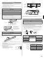
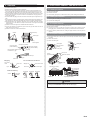
[Troubleshooting with the indoor unit display]
OPERATION
TIMER
ECONOMY
OPERATION lamp (green)
TIMER lamp (orange)
ECONOMY lamp (green)
[Troubleshooting with the Wired Remote Controller Display (Option)]
If an error occurs, the following display will be shown. (“Er” will appear in
the set room temperature display.)
Error code
Inverter error
Active ¿lter error, PFC circuit
error
• Sub-cool Heat Ex. gas inlet
temp. sensor error
• Sub-cool Heat Ex. gas outlet
temp. sensor error
Liquid pipe temp. sensor error
En-10