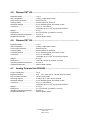
1
User Manual
Power Express
User Manual Power Express
UM012_04, 22.03.2007
Copyright © CUE, a.s. Praha, Czech Republic 1996 - 2006.
All rights reserved. Specifications are subject to change without prior notice.
Table of Contents
1. Introduction....................................................................................................................................... 4
1.1.
1.2.
1.3.
Overview.............................................................................................................................................. 4
Models ................................................................................................................................................. 4
Features .............................................................................................................................................. 5
2. System Block Diagram .................................................................................................................... 6
3. Control Units..................................................................................................................................... 7
3.1.
3.2.
3.3.
3.4.
3.5.
3.6.
3.7.
3.8.
3.9.
3.10.
Converter PEC25................................................................................................................................. 7
Dimmer PED108.................................................................................................................................. 8
Dimmer PED202.................................................................................................................................. 9
Dimmer PET102 .................................................................................................................................10
Dimmer PET105 .................................................................................................................................11
Analog Outputs Interface PEA208 ......................................................................................................12
Dimming Ballasts Interface PEF150 ...................................................................................................13
Dimming Ballasts Interface PEF200 ...................................................................................................14
Switching Unit PER610.......................................................................................................................15
Suppressor PES03 .............................................................................................................................16
4. Specifications ................................................................................................................................. 17
4.1.
4.2.
4.3.
4.4.
4.5.
4.6.
4.7.
4.8.
4.9.
4.10.
4.11.
General...............................................................................................................................................17
Converter PEC25................................................................................................................................17
Dimmer PED108.................................................................................................................................17
Dimmer PED202.................................................................................................................................17
Dimmer PET102 .................................................................................................................................18
Dimmer PET105 .................................................................................................................................18
Analog Outputs Unit PEA208 .............................................................................................................18
Dimming Ballasts Interface PEF150 ...................................................................................................19
Dimming Ballasts Interface PEF200 ...................................................................................................19
Switching Unit PER610.......................................................................................................................19
Suppressor PES03 .............................................................................................................................19
5. Software and Firmware License ................................................................................................... 20
6. Warranty Conditions ...................................................................................................................... 21
7. CE Declaration of Conformity ....................................................................................................... 22
8. FCC .................................................................................................................................................. 23
User Manual Power Express
www.cue.cz
Page 3 of 24
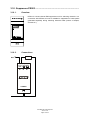
1. Introduction
1.1. Overview ..........................................................................................
Power Express is a modular system, which controls lights, drapes, screens etc. All modules are fully
compatible with ipCUE, Assistant and Assistant-S. It is suitable wherever sensitive work with light
system is needed, or central control by integrated control system is necessary. Simple installation into
a switchboard on DIN rail, small dimensions. The 2.5 kV isolation between power and control circuits.
Easy programming of parameters on PC under Windows. Immediate information about status of the
modules. Manual control by contact closure and switches (any standard types). Communication
between modules via PEbus - two twisted-pair cables. Interference suppression according to EN55014
and EN55011 norm.
Usage for
•
•
•
•
•
•
•
Smart houses
Conference and versatile halls, boardrooms
Classrooms, auditorium (with video projection)
Entertaining halls
Theatres, galleries, museums
Information centers
Exhibition stands
1.2. Models ..............................................................................................
Model
Product code
Description
PEC25
CS0163
Converter between RS-232 and PEbus.
PED108 (version 110VAC)
CS0164-1
One-channel dimmer. Output 1x 110 VAC, 8 A.
PED108 (version 230 VAC)
CS0164-2
One-channel dimmer. Output 1x 230 VAC, 8 A.
PED202 (version 110 VAC)
CS0165-1
Two-channel dimmer. Output 2x 110 VAC, 2.7 A (total max. 4 A).
PED202 (version 230 VAC)
CS0165-2
Two-channel dimmer. Output 2x 230 VAC, 2.7 A (total max. 4 A).
PET102 (version 110 VAC)
CS0244-1
One-channel dimmer. Output 1x 110 VAC, 2A
PET102 (version 230 VAC)
CS0244-2
One-channel dimmer. Output 1x 230 VAC, 2A
PET105 (version 110 VAC)
CS0245-1
One-channel dimmer. Output 1x 110 VAC, 5A
PET105 (version 230 VAC)
CS0245-2
One-channel dimmer. Output 1x 230 VAC, 5A
PEA208 (version 110 VAC)
CS0225-1
Two-channel analog output 0 - 10 V
PEA208 (version 230 VAC)
CS0225-2
Two-channel analog output 0 - 10 V
PEF150 (version 110 VAC)
CS0249-1
15-channel controller for DALI fluo lamp dimming ballasts.
PEF150 (version 230 VAC)
CS0249-2
15-channel controller for DALI fluo lamp dimming ballasts.
PEF200 (version 110 VAC)
CS0166-1
Two-channel controller for DSI fluo lamp dimming ballasts.
PEF200 (version 230 VAC)
CS0166-2
Two-channel controller for DSI fluo lamp dimming ballasts.
PER610 (version 110 VAC)
CS0167-1
Six-channel relay unit. Output 6x max. 230 VAC, 10 A.
PER610 (version 230 VAC)
CS0167-2
Six-channel relay unit. Output 6x max. 230 VAC, 10 A.
PES03
CS0168
Three-channel suppressor unit.
User Manual Power Express
www.cue.cz
Page 4 of 24
1.3. Features ...........................................................................................
•
•
•
•
•
•
•
Easy installation (into switchboard on DIN rail)
Small dimensions
Consistent galvanic isolation between control and power circuits
Easy setting of parameters (under Windows PC application)
Immediate information about current status of the units
Manual control from current push buttons and switches (great variety of designs and colors)
Communication between units and switchboards via twisted pair cable.
Serial control from CUE controllers (port S1 on ipCUE, S9/CUEring on Assistant) via PEbus.
User Manual Power Express
www.cue.cz
Page 5 of 24
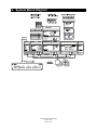
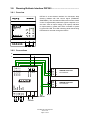
2. System Block Diagram
User Manual Power Express
www.cue.cz
Page 6 of 24
3.
Control Units
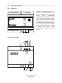
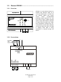
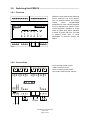
3.1. Converter PEC25 .............................................................................
3.1.1. Overview
PEC25 is a converter between RS-232 and PEbus. Transmission way
indication by LED indicators. Host computer connector on the front panel
for system setup.
3.1.2. Connections
TxD
RxD
GND
GND
The connector Sub-D, 9-pin, female and terminals are connected in parallel. TxD means transmit data,
RxD means receive data and GND is a digital ground.
Cable from ipCUE to PEC25
5
9
1
SUBD 9F
6
2 - TxD
3 - RxD
5 - GND
DB9 – Male rear view
to PEC25
Phoenix 5-pin 3.5 mm
to S1 port on ipCUE
PEbus
User Manual Power Express
www.cue.cz
Page 7 of 24
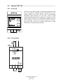
3.2. Dimmer PED108 ..............................................................................
3.2.1. Overview
PED108 is a one-channel dimmer for
resistive and inductive loads up to 8 A.
The unit features PEbus and contact
closure
control.
Programmable
parameters (input response, min. and
max. value of output voltage, dimming
speed, output characteristic). Indication
of output level by yellow OUT LED,
max. temperature overload and overcurrent fuse by red F/O LED. Indication
of power by green P/D LED. This LED
is flashing while data is being
transmitted or received through the
PEbus.
3.2.2. Connections
N
L
DOWN
UP
GND
OUT
OUT
NEUTRAL
NEUTRAL
LIVE
LIVE
LOAD
max. 8 A
PEbus
User Manual Power Express
www.cue.cz
Page 8 of 24
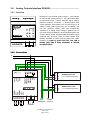
3.3. Dimmer PED202 ..............................................................................
3.3.1. Overview
PED202 is a two-channel dimmer for
resistive and inductive loads up to
2.7 A per channel (max. 4 A total). The
unit features PEbus and contact
closure
control.
Programmable
parameters (input response, min. and
max. value of output voltage, dimming
speed, output characteristic). Indication
of output levels by yellow OUT LEDs,
max. temperature overload and overcurrent fuse by red F/O LED. Indication
of power by green P/D LED. This LED
is flashing while data is being
transmitted or received through the
PEbus.
3.3.2. Connections
N
L
DOWN1
UP1
GND
DOWN2
UP2
GND
OUT1
OUT2
NEUTRAL
NEUTRAL
LIVE
LIVE
2 x LOAD
total
max. 4 A
PEbus
User Manual Power Express
www.cue.cz
Page 9 of 24
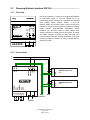
3.4. Dimmer PET102 ...............................................................................
3.4.1. Overview
PET102 is a one-channel dimmer for resistive and capacitive loads
up to 2 A suitable for dimmable electronic transformers. The unit
features PEbus and contact closure control. Programmable
parameters (input response, min. and max. value of output
voltage, dimming speed, output characteristic). Indication of output
level by yellow OUT LED, max. temperature overload and overcurrent electronic fuse by red F/O LED. Indication of power by
green P/D LED. This LED is flashing while data is being
transmitted or received through the PEbus.
3.4.2. Connections
N
L
DOWN
UP
GND
OUT
NEUTRAL
NEUTRAL
LIVE
LIVE
LOAD
max. 2 A
PEbus
User Manual Power Express
www.cue.cz
Page 10 of 24
3.5. Dimmer PET105 ...............................................................................
3.5.1. Overview
PET105 is a one-channel dimmer for
resistive and capacitive loads up to 5 A
suitable for dimmable electronic
transformers. The unit features PEbus
and
contact
closure
control.
Programmable
parameters
(input
response, min. and max. value of
output voltage, dimming speed, output
characteristic). Indication of output level
by yellow OUT LED, max. temperature
overload and over-current electronic
fuse by red F/O LED. Indication of
power by green P/D LED. This LED is
flashing while data is being transmitted
or received through the PEbus.
3.5.2. Connections
N
L
DOWN
UP
GND
OUT
NEUTRAL
NEUTRAL
LIVE
LIVE
LOAD
max. 5 A
PEbus
User Manual Power Express
www.cue.cz
Page 11 of 24
3.6. Analog Outputs Interface PEA208 .................................................
3.6.1. Overview
PEA208 is a two-channel analog output 0 - 10V interface
for devices with analog control 0 - 10V (dimmable ballast
for fluorescent lamps – Osram, Siemens, Helvar, Philips,
dimmers, frequency converters ...). Analog outputs have
10–bit resolution (1024 levels). Sink current can be up to
100mA to each output (more then 100 of ballasts). Unit
has two switching outputs (max. 8A) automatically
switched on, if analog output voltage is greater then 1V
(for power supply of ballasts). The unit features PEbus and
contact closure control. Programmable parameters (inputs
response, min. and max. value of output voltage, scan
speed). Indication of output levels by yellow OUT LEDs.
Indication of power by green P/D LED. This LED is
flashing while data is being transmitted or received
through the PEbus.
3.6.2. Connections
N
PWR OUT1
PWR OUT2
NEUTRAL
NEUTRAL
LIVE
LIVE
DOWN1
UP1
GND
DOWN2
UP2
GND
OUT1+
OUT1OUT2+
OUT2-
L
max.
100 ballasts
LOAD
max. 8 A
PEbus
User Manual Power Express
www.cue.cz
Page 12 of 24
N
L
A+
A-
DIMMABLE BALLAST
1-10 V ANALOG CONTROL
N
L
A+
A-
DIMMABLE BALLAST
1-10 V ANALOG CONTROL
3.7. Dimming Ballasts Interface PEF150 ..............................................
3.7.1. Overview
PEF150 is interface for control up to 64 dimmable ballasts
for fluorescent lamps on one bus divided up to 15
independent groups. Interface is compatible with ballasts
DALI (Philips, Osram, Tridonic, Helvar ...). The unit
features PEbus and contact closure control. All groups is
possible to control by PEXbus and two of them by external
press buttons. Programmable parameters (inputs
response, min. and max. value of output voltage, scan
speed). Indication of output levels of two groups by yellow
G/S LEDs. Indication of power by green P/D LED. This
LED is flashing while data is being transmitted or received
through the PEbus. Indication of DALI communication by
yellow OUT LED.
3.7.2. Connections
N
NEUTRAL
NEUTRAL
LIVE
LIVE
DOWN1
UP1
GND
DOWN2
UP2
GND
DA
DA
L
max.
64 ballasts
PEbus
User Manual Power Express
www.cue.cz
Page 13 of 24
N
L
DA
DA
DIMMABLE BALLAST
DALI
N
L
DA
DA
DIMMABLE BALLAST
DALI
3.8. Dimming Ballasts Interface PEF200 ..............................................
3.8.1. Overview
PEF200 is a two-channel interface for fluorescent lamp
dimming ballasts with DSI control signal (TRIDONIC,
ZUMTOBEL). The unit features PEbus and contact closure
control. Programmable parameters (inputs response, min.
and max. value of output voltage, scan speed). Indication
of output levels by yellow OUT LEDs. Indication of power
by green P/D LED. This LED is flashing while data is being
transmitted or received through the PEbus.
3.8.2. Connections
N
NEUTRAL
NEUTRAL
LIVE
LIVE
DOWN1
UP1
GND
DOWN2
UP2
GND
OUT1D1
OUT1D2
OUT2D1
OUT2D2
L
max.
50 ballasts
PEbus
User Manual Power Express
www.cue.cz
Page 14 of 24
N
L
D1
D2
DIMMABLE BALLAST
DSI CONTROL
N
L
D1
D2
DIMMABLE BALLAST
DSI CONTROL
3.9. Switching Unit PER610 ...................................................................
3.9.1. Overview
PER610 is a six-channel relay switching
unit for loads up to 10 A per channel.
The unit features PEbus and contact
closure
control.
Programmable
parameters for each channel (response
on input, delayed on/off, memory, motor
control sequence). Indication of output
status by yellow OUT LEDs. Indication
of power by green P/D LED. This LED
is flashing while data is being
transmitted or received through the
PEbus.
3.9.2. Connections
GND
IN4
IN5
IN6
NC4
COM4
NO4
NC5
COM5
NO5
NC6
COM6
NO6
GND
IN1
IN2
IN3
LIVE
LIVE
NEUTRAL
NEUTRAL
NC1
COM1
NO1
NC2
COM2
NO2
NC3
COM3
NO3
NC is normally closed contact.
COM is common contact.
NO is normally opened contact.
Max. load is 230V/10A per channel.
PEbus
L
N
User Manual Power Express
www.cue.cz
Page 15 of 24
3.10. Suppressor PES03 ..........................................................................
3.10.1.
Overview
PES03 is a three-channel EMI suppressor unit for switching channels. In a
connection with PER610, this unit is suitable for suppression of noise peaks
generated especially during switching inductive loads (motors of drapes,
screens etc.)
3.10.2.
Connections
LOAD
CH3
CH2
CH1
L
COMMON
N
User Manual Power Express
www.cue.cz
Page 16 of 24
4.
Specifications
4.1. General
EMI radiation .......................................According to EN55014 and EN55011 standard
Power supply .......................................230 VAC (version 230V) or 110 VAC (version 110V), 50/60 Hz
Communication....................................PEbus (RS-485)
Enclosure.............................................Plastic
Storage temperature............................-20 to 90 °C
4.2. Converter PEC25 .............................................................................
Power supply .......................................From PEbus or external 7.5 - 30 VDC, 100 mA
Baud rate .............................................19 200 bits/sec
Connectors ..........................................2x RJ-11-4 for PEbus
Sub-D, 9-pin, female for RS-232
Terminals for RS-232
Weight..................................................0.1 kg
Dimensions..........................................36 x 90 x 58 mm (2 modules 17.5 mm)
Operating ambient temperature ..........0 to 60 °C
Supplied accessories...........................PEbus Cable CA0130
4.3. Dimmer PED108 ..............................................................................
Regulated output .................................1x 8 A
Way of regulation.................................Leading - edge phase control
Over-current protection........................Quick-brake fuse 5 x 20 mm, F8A
Cooling system ....................................Passive aluminum heat sink
Insulation strength ...............................2.5 kV between power and control circuits
Connectors ..........................................2x RJ-11-4 for PEbus
Terminals up to 1.5 mm2 for inputs and outputs
Weight..................................................0.75 kg
Dimensions..........................................106 x 90 x 58 mm (6 modules 17.5 mm)
Operating ambient temperature ..........0 to 40 °C
Supplied accessories...........................PEbus Cable CA0130
4.4. Dimmer PED202 ..............................................................................
Regulated outputs ...............................2x 2.7 A per channel (4 A total)
Way of regulation.................................Leading - edge phase control
Over-current protection........................Quick-brake fuse 5 x 20 mm, F4A
Cooling system ....................................Passive aluminum heat sink
Insulation strength ...............................2.5 kV between power and control circuits
Connectors ..........................................2x RJ-11-4 for PEbus
Terminals up to 1.5 mm2 for inputs and outputs
Weight..................................................0.5 kg
Dimensions..........................................106 x 90 x 58 mm (6 modules 17.5 mm)
Operating ambient temperature ..........0 to 40 °C
Supplied accessories...........................PEbus Cable CA0130
User Manual Power Express
www.cue.cz
Page 17 of 24
4.5. Dimmer PET102 ...............................................................................
Regulated output .................................1x 2 A
Way of regulation.................................Trailing - edge phase control
Over-current protection........................Electronic fuse
Cooling system ....................................Passive aluminum heat sink
Insulation strength ...............................2.5 kV between power and control circuits
Connectors ..........................................2x RJ-11-4 for PEbus
Terminals up to 1.5 mm2 for inputs and outputs
Weight..................................................0.5 kg
Dimensions..........................................53 x 90 x 58 mm (3 modules 17.5 mm)
Operating ambient temperature ..........0 to 40 °C
Supplied accessories...........................PEbus Cable CA0130
4.6. Dimmer PET105 ...............................................................................
Regulated output .................................1x 5 A
Way of regulation.................................Trailing - edge phase control
Over-current protection........................Electronic fuse
Cooling system ....................................Passive aluminum heat sink
Insulation strength ...............................2.5 kV between power and control circuits
Connectors ..........................................2x RJ-11-4 for PEbus
Terminals up to 1.5 mm2 for inputs and outputs
Weight..................................................0.75 kg
Dimensions..........................................106 x 90 x 58 mm (6 modules 17.5 mm)
Operating ambient temperature ..........0 to 40 °C
Supplied accessories...........................PEbus Cable CA0130
4.7. Analog Outputs Unit PEA208 .........................................................
Power consumption .............................12 W
Regulated outputs ...............................2x 0 – 10V, 15mA source, 100 mA sink per channel
D/A converter resolution ......................10 bits (1024 levels)
Switching outputs ................................2 relays, up to 230V, 8A per channel
Insulation strength ...............................2.5 kV between power and control circuits
Connectors ..........................................2x RJ-11-4 for PEbus
Terminals up to 1.5 mm2 for inputs and outputs
Weight..................................................0.25 kg
Dimensions..........................................71 x 90 x 58 mm (4 modules 17.5 mm)
Operating ambient temperature ..........0 to 60 °C
Supplied accessories...........................PEbus Cable CA0130
User Manual Power Express
www.cue.cz
Page 18 of 24
4.8. Dimming Ballasts Interface PEF150 ..............................................
Power consumption .............................12 W
Output ..................................................15 groups, up to 64 electronic DALI compatible ballasts
Connectors ..........................................2x RJ-11-4 for PEbus
Terminals up to 1.5 mm2 for inputs and outputs
Weight..................................................0.25 kg
Dimensions..........................................71 x 90 x 58 mm (4 modules 17.5 mm)
Operating ambient temperature ..........0 to 60 °C
Supplied accessories...........................PEbus Cable CA0130
4.9. Dimming Ballasts Interface PEF200 ..............................................
Power consumption .............................12 W
Outputs ................................................2x up to 50 electronic DSI compatible ballasts per channel
Connectors ..........................................2x RJ-11-4 for PEbus
Terminals up to 1.5 mm2 for inputs and outputs
Weight..................................................0.25 kg
Dimensions..........................................71 x 90 x 58 mm (4 modules 17.5 mm)
Operating ambient temperature ..........0 to 60 °C
Supplied accessories...........................PEbus Cable CA0130
4.10. Switching Unit PER610 ...................................................................
Power consumption .............................12 W
Outputs ................................................6 relays, up to 230 VAC, 10 A per channel
Insulation strength ...............................2.5 kV between power and control circuits
Connectors ..........................................2x RJ-11-4 for PEbus
Terminals up to 1.5 mm2 for inputs and outputs
Weight..................................................0.5 kg
Dimensions..........................................106 x 90 x 58 mm (6 modules 17.5 mm)
Operating ambient temperature ..........0 to 60 °C
Supplied accessories...........................PEbus Cable CA0130
4.11. Suppressor PES03 ..........................................................................
Number of suppressed channels.........3
Max. load voltage ................................275 VAC
Max. load current.................................10 A
Connectors ..........................................Terminals up to 1.5 mm2 for inputs and outputs
Weight..................................................0.1 kg
Dimensions..........................................36 x 90 x 58 mm (2 modules 17.5 mm)
Operating ambient temperature ..........0 to 60 °C
User Manual Power Express
www.cue.cz
Page 19 of 24
5.
Software and Firmware License
END-USER NOTICE AND LICENSE AGREEMENT FROM CUE, a.s.
NOTICE TO END-USER: CAREFULLY READ THE FOLLOWING LEGAL AGREEMENT (THIS "LICENSE").
INSTALLATION OR USE OF THE ENCLOSED CUE, a.s. SOFTWARE PROGRAMS (COLLECTIVELY,
"SOFTWARE") ON YOUR COMPUTER SYSTEMS OR HARDWARE DEVICES CONSTITUTES YOUR
ACCEPTANCE OF THESE TERMS. IF YOU DO NOT AGREE TO THE TERMS OF THIS LICENSE, PROMPTLY
DELETE THE SOFTWARE FROM YOUR COMPUTER SYSTEMS AND HARDWARE DEVICES, DESTROY
ANY COPIES YOU MADE OF THE SOFTWARE OR ANY INSTALLATION MEDIA OF THE SOFTWARE
INCLUDED WITH YOUR SYSTEM, AND DISPOSE OF ALL WRITTEN MATERIALS IN YOUR POSSESSION
REGARDING THE SOFTWARE.
License Grant: CUE grants to You, as an individual, a license to install and use one (1) copy of the Software on
a single computer at a time; provided, however, that You may make copies of the Software solely for Your
development of applications for CUE hardware and demonstration versions of such applications. Any applications
created with the Software may only be used with Cue hardware. Your license to use the Software is conditioned
upon Your compliance with the terms of this License. A License is required for each end-user of the Software. A
license is required for each installation of the Software. You may make one (1) copy of the Software for archival
purposes only. You may use this Software only in connection with CUE hardware. You must have acquired the
Software directly in connection with the purchase of CUE hardware from CUE or from a CUE approved reseller
for this license to be effective. If You have purchased a Site License, You may complete only the number of
installations specified in the License Agreement accompanying the Software.
Copyright: The Software and software built into CUE hardware ("Firmware") are protected by copyright law and
international treaty provisions. You acknowledge that no title to the intellectual property in the Software and
Firmware is transferred to You. You further acknowledge that title and full ownership rights to the Software and
Firmware will remain the exclusive property of CUE, and You will not acquire any rights to the Software and
Firmware except as expressly set forth in this License. You agree that any copies of the Software will contain the
same proprietary notices which appear on and in the Software.
Prohibited Uses: Without obtaining prior written permission from CUE, You may not (a.) use, copy, modify, alter,
or transfer the Software or documentation except as expressly provided in this License; (b.) translate,
disassemble, decompile, reverse program or otherwise reverse engineer the Software and Firmware; (c.)
sublicense or lease the Software or its documentation (d.) use this Software with any hardware other than
products produced by CUE or in connection with applications being developed for CUE hardware; or (e.) use the
Software in a multi-user, network, or multiple computer environment or in a rental, time sharing or computer
service business. Without prejudice to any other rights, CUE may terminate this License if You fail to comply with
its terms and conditions. In such event, You must immediately destroy all copies of the Software.
No Other Warranties: CUE DOES NOT WARRANT THAT THE SOFTWARE AND FIRMWARE IS ERROR
FREE. CUE DISCLAIMS ALL WARRANTIES WITH RESPECT TO THE SOFTWARE AND FIRMWARE, EITHER
EXPRESS OR IMPLIED, INCLUDING BUT NOT LIMITED TO IMPLIED WARRANTIES OF MERCHANTABILITY,
FITNESS FOR A PARTICULAR PURPOSE AND NONINFRINGEMENT OF THIRD PARTY RIGHTS. SOME
JURISDICTIONS DO NOT ALLOW THE EXCLUSION OF IMPLIED WARRANTIES OR LIMITATIONS OF HOW
LONG AN IMPLIED WARRANTY MAY LAST, OR THE EXCLUSION OF LIMITATION OF INCIDENTAL
DAMAGES, SO THE ABOVE LIMITATIONS OR EXCLUSIONS MAY NOT APPLY TO YOU. THIS WARRANTY
GIVES YOU SPECIFIC LEGAL RIGHTS AND YOU MAY ALSO HAVE OTHER RIGHTS WHICH VARY FROM
JURISDICTION TO JURISDICTION.
No Liability for Consequential Damages: IN NO EVENT SHALL CUE BE LIABLE TO YOU FOR ANY
CONSEQUENTIAL, SPECIAL, INCIDENTAL, OR INDIRECT DAMAGES OF ANY KIND ARISING OUT OF THE
PERFORMANCE OR USE OF THE SOFTWARE, EVEN IF CUE HAS BEEN ADVISED OF THE POSSIBILITY
OF SUCH DAMAGES.
Label on Hardware: Use of this hardware and the software programs controlling this hardware is subject to the
terms of the Software and Hardware License Agreements (the “License Agreements”). You should not use the
software and hardware until you have read the License Agreements. By using the software and hardware, you
signify that you have read the Licenses Agreements and accept their terms. The “License Agreement” is available
at www.cuesystem.com.
Trademark Notice: CUE and the CUE logo are trademarks of CUE, a.s. in the United States and in other
countries.
User Manual Power Express
www.cue.cz
Page 20 of 24
6.
Warranty Conditions
Warranty Duration
CUE, a.s. provides warranty for all CUE products for a period of 3 years from the day of purchase. The provided warranty for
touch screens is 2 years from the day of purchase. CUE accepts reclamation of 5 not properly working dots and more (2 dots
join – 1 counts). The warranty provided for rechargeable accumulators is 6 months from the day of purchase
Liability
CUE is not liable for any consequential damage caused by CUE products including any loss of profits, incidental or
consequential damages or any claims made by a third parties.
General Warranty Terms
a)
b)
c)
d)
CUE warrants that its products are without defects in material and are fully functional for the duration of the warranty.
Warranty repairs are free of charge. The customer will send the damaged device to CUE at his cost.
All warranty repairs and after warranty services are made at CUE premises. It is strictly prohibited to repair CUE
products or to change any accessory parts, except those parts with limited service life. CUE is not liable for
consumables or parts with limited service life (lamps, batteries etc.)
The warranty further does not apply to the following cases
•
Damages caused by operating the system not according to the conditions defined in user manual or
instruction (wrong power supply voltage, operation outside deferred temperature range, operation in humid
environment and mechanical damages).
•
Damages caused by faulty service, maintenance, connection, and use of other than original connection
cable.
•
Damage caused by agencies i.e. incidental or unpredictable impacts (fire, earthquake, flood, thunder,
strong electric induction, water, strong wind, theft, vandalism etc.)
After Warranty Services
a)
b)
c)
All warranty repairs are normally on a ‘back to base’ basis, as defined in 3 c)
All out warranty repair costs will be fully charged to the customer.
In cases where our staff are called out to assist, cost of transport and time will be at customer cost
User Manual Power Express
www.cue.cz
Page 21 of 24
7.
CE Declaration of Conformity
CE Declaration of Conformity
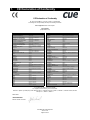
We, the producer CUE, a.s., K Nouzovu 6, Praha 4, Czech Republic
acknowledge our sole responsibility, that the product including accessories
Kind of equipment: Remote Control System
Type designation
(in alphabetical order)
Product Name
Product Code
Product Name
Product Code
airCUE-6X10
CS0300-001 to CS0300-005
PET105
CS0245-1, CS0245-2
airCUE-6X10 Tabletop Docking Station
CS0301-001 to CS0301-005
powerAUX
CS0016
airCUE-6X10 Tabletop Stand
CS0303-001
rfbaseCUE
CS0171-4, CS0171-8, CS0171-9
airCUE-6X10 Wall Docking Station
CS0302-001 to CS0302-005
rfCUE 99
CS0170-*4A, CS0170-*8A, CS0170-*9A
airCUE-6X10 Wall Mounting Adapter
CS0304-001
Rx Ext
CS0319.401
airCUE-8X10
CS0305-001 to CS0305-005
Rx1 DIN / Data Receiver
CS0318.401
airCUE-8X10 Tabletop Docking Station
CS0306-001 to CS0306-005
sbiCUE-DMX
CS0201
airCUE-8X10 Tabletop Stand
CS0308-001
sensorCUE
CS0265
airCUE-8X10 Wall Docking Station
CS0307-001 to CS0307-005
smartCUE
CS0008-R, CS0008-M
airCUE-8X10 Wall Mounting Adapter
CS0309-001
soundCUE
CS0009
airCUE-XM8
CS0254-W, CS0254-O, CS0254-M
touchCUE-L
CS0236
airCUE-XM8 Docking Station
CS0260-W, CS0260-O, CS0260-M
touchCUE-L / b
CS0238
analogCUE
CS0004
touchCUE-L / b Back Box
CS0238-MB
auxCUE
CS0005
touchCUE-L / b Rack Mount Panel
CS0238-MR
CUEadapter / 30W
CS0292-001 to CS0292-003
touchCUE-LV
CS0236-V
CUEadapter / 65W
CS0293-001 to CS0293-003
touchCUE-LV / b
CS0238-V
CUEwire Converter 232/ 422/ 485
CS0233
touchCUE-LV 99
CS0234-W-V, , S0234-O -V, CS0234-M-V
eCUE
CS0173
touchCUE-M
CS0237
inputCUE
CS0191
touchCUE-M / b
CS0239
ipCUE-alpha
CS0251
touchCUE-M / b Back Box
CS0239-MB
ipCUE-beta
CS0252
touchCUE-M / b Rack Mount Panel
CS0239-MR
ipCUE-delta
CS0267
touchCUE-MV
CS0237-V
ipCUE-epsilon
CS0268
touchCUE-MV / b
CS0239-V
ipCUE-gamma
CS0253
touchCUE-MV 99
CS0235-W-V, CS0235-O -V, CS0235-M-V
ipCUE Rack Mounting Kit
CS0251-MR
touchCUE-S
CS0247
IR Adapter / i
CS0256
touchCUE-S / b
CS0241
irCUE 99
CS0149-WA, CS0149-OA, CS0149-MA
touchCUE-S / b Back Box
CS0241-MB
irCUE Receiver 485
CS0169-C
touchCUE-S / b Rack Mount Panel
CS0241-MR
keyboardCUE-S
CS0174-W, CS0174-O, CS0174-M
touchCUE-S 99
CS0248-W, CS0248-O , CS0248-M
keyboardCUE 99
CS0145-W, CS0145-O, CS0145-M
touchCUE-SRF
CS0188-4, CS0188-8, CS0188-9
keypadCUE-1G
CS0221
touchCUE-SX / b
CS0266
keypadCUE-2G
CS0222
touchCUE-SX / b Back Box
CS0266-MB
keypadCUE-3G
CS0223
touchCUE-SX / b Rack Mount Panel
CS0266-MR
monitorCUE
CS0203-W, CS0203-O, CS0203-M
touchCUE-V / i
CS0190
O pto-Input Adapter / i
CS0257
touchCUE-XLV 99
CS0261-W-V, CS0261-O -V, CS0261-M-V
PEA208
CS0225-1, CS0225-2
Tx Cross 4
CS0317.401
PEC25
CS0163
Tx Element 2
CS0312.401 to CS0312.424
PED108
CS0164-1, CS0164-2
Tx Element 4
CS0313.401 to CS0313.424
PED202
CS0165-1, CS0165-2
Tx Key
CS0316.401
PEF150
CS0249-1, CS0249-2
Tx Pocket 1
CS0314.401
PEF200
CS0166-1, CS0166-2
Tx Pocket 4
CS0315.401
PER610
CS0167-1, CS0167-2
Tx Time 2
CS0310.401 to CS0310.434
PES03
CS0168
Tx Time 4
CS0311.401 to CS0311.434
PET102
CS0244-1, CS0244-2
Universal Serial Cable Adapter
CS0271
in accordance with EMC Directive 89/ 336/ EEC,
is in compliance with the following norms or documents:
EN50082-1 (IEC801-2), IEC65(CO )39, DIN VDE 0839 part 82-1, DIN VDE 0843 part 4, IEC801-4, EN50081-1, EN55022 class B, DIN VDE
0839 part 81-1, EN55014, EN55011.
28.5.2007
Jaroslav Dibitanzl
Member of Board of Directors
User Manual Power Express
www.cue.cz
Page 22 of 24
8.
FCC
Caution
Changes or modifications to this unit not expressly approved by the party responsible for compliance could void the user's
authority to operate the equipment.
Note
This equipment has been tested and found to comply with the limits for a Class B digital device, pursuant to Part 15 of the FCC
Rules. These limits are designed to provide reasonable protection against harmful interference in a residential installation. This
equipment generates, uses and can radiate radio frequency energy and, if not installed and used in accordance with the
instructions, may cause harmful interference to radio communications. However, there is no guarantee that interference will not
occur in a particular installation. If this equipment does cause harmful interference to radio or television reception, which can be
determined by turning the equipment off and on, the user is encouraged to try to correct the interference by one or more of the
following measures:
•
Reorient or relocate the receiving antenna.
•
Increase the separation between the equipment and receiver.
•
Connect the equipment into an outlet on a circuit different from that to which the receiver is connected.
•
Consult the dealer or an experienced radio / TV technician for help.
User Manual Power Express
www.cue.cz
Page 23 of 24
Notes
User Manual Power Express
www.cue.cz
Page 24 of 24