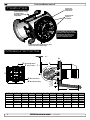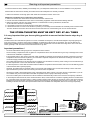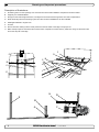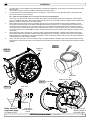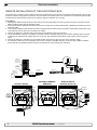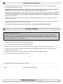
1
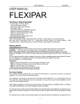
SIDE-POWER Thruster Systems 90150i Stern thruster installation manual ! This manual is to be used in addition to the regular installation manual for the Sidepower thruster. is rd th a p bo ee n K al o u an m IMPORTANT NOTICE: SLEIPNER MOTOR AS P.O. Box 519 N-1612 Fredrikstad Norway Tel: +47 69 30 00 60 Fax: +47 69 30 00 70 w w w. s i d e - p o w e r. c o m s i d e p o w e r @ s l e i p n e r. n o Made in Norway This manual is intended for professionals only, and does not contain all detailed work instructions for what must be done to ensure correct and safe installation of the sternthruster. © Sleipner Motor AS 2015 Features/Measurements EN Features Groves for application of sealant Tunnel halves snaps together after mounting gearleg/ propellers Extra metal support brackets The combination of metal brackets and support struts eliminates the need for a seperate support for the motor inside the boat Integrated support struts for each of the 4 motor bracket legs Measurements W.L. B2 E D (Outer flange diam.) F 60° I (Cut-out diam.) B C Bolt holes diaG : Bolt pos tion radiusH: Cut out in s tern: F E D (Bolt holes diam.) (Bolt position diam.) PS ! Necessary support of motor. Minimum is hulls bottom thickness G Outs ide of flange: H A Thruster A B B2(max) C D E F G H I SE(P) 130 363mm/14.2” 345mm/13.6” 105mm/4.1” 250mm/9.84” 350mm/13.8” 350mm/13.8” 270mm/10.6” 8x10.5mm/0.41” 308mm/12.1” 330mm/13” SE(P) 130 IP 390mm/15.4” 345mm/13.6” 105mm/4.1” 250mm/9.84” 350mm/13.8” 350mm/13.8” 270mm/10.6” 8x10.5mm/0.41” 308mm/12.1” 330mm/13” SE(P) 170 386mm/15.2” 345mm/13.6” 105mm/4.1” 250mm/9.84” 350mm/13.8” 350mm/13.8” 270mm/10.6” 8x10.5mm/0.41” 308mm/12.1” 330mm/13” SE(P) 170 IP 390mm/15.4” 345mm/13.6” 105mm/4.1” 250mm/9.84” 350mm/13.8” 350mm/13.8” 270mm/10.6” 8x10.5mm/0.41” 308mm/12.1” 330mm/13” SE(P) 210 424mm/16.7” 345mm/13.6” 63mm/2.5” 250mm/9.84” 350mm/13.8” 350mm/13.8” 270mm/10.6” 8x10.5mm/0.41” 308mm/12.1” 330mm/13” SH 240 195mm/7.7” 345mm/13.6” - 250mm/9.84” 350mm/13.8” 350mm/13.8” 270mm/10.6” 8x10.5mm/0.41” 308mm/12.1” 330mm/13” 2 90150i Stern thruster tunnel 1.0.3- 2015 THE STERN-THRUSTER MUST BE KEPT DRY AT ALL TIMES Planning and important precautions ItEN is very important that you do everything possible to ensure that the thruster stays dry at allTotimes. achieve maximum effect, reliability and durability from your Sidepower Sternthruster, a correct installation is very important. Please follow the instructions carefully, and make sure that all checkpoints are carefully controlled. The electromotor and and solenoid system is not to be considered as waterproof, and will be dammaged if they keep getting corriosion). Therefore, the thrusters installation compartment must be kept dry at all 1.Make surewet that(rust there and are enough space both inside and outside the transom of the boat. times. Additional considerations for positioning of stern thruster: This is more for a sternthruster installation than forunder a bowthruster installation as the sternthruster has to be o Make suredifficult that the stern-tunnel does not disturb the waterflow the hull o Ensure when installed doesThis not foul exisiting equipment likebe steerage links etc.into a dry area. fitted in thethat bilge at the sterntheofthruster the boat. is generally a “wet”inside area the thatboat must transformed sure that the water flow from the thruster are not intereferred to much by sterndrives, trimtabs etc. KEPTo Make DRY ATthe thrust ALL TIMES as this will reduce considerably. o It is possible to mount the off the boat’s centre line if necessary. Important precautions ! tunnel ensure the thruster stays atin question you can easily remove material in the necessary area to fit the thruster. o Ifthat the stern thickness is to much for thedry thruster - mustthickness seal all even drainhere holes into to thebecompartment of the thruster. given as max. stern thickness. You The stern willgoing never have less than the max. measurement - The surrounding compartments and any plates or compartments above must be drained in a good way to the THE STERN-THRUSTER MUST BE KEPT DRY AT ALL TIMES bilge and areawill in front of the thrusters installation compartment. s waterproof, be dammaged if they isIf very important you do everything to ensure that comes the thruster dry of at the llation- Itcompartment must dry at all the propeller shaftbethat orkept other moving parts with apossible high possibility for leakage through stays the bottom all boat times. same compartment where the thruster is placed, you must make a seperate compartment for the in the Thethruster electromotor and and solenoid system not considered waterproof, and leakages. will be dammaged if they keep getting wet isolating it from these veryistonormal highlyasprobable water uster installation as the sternthruster has beto beand (rust and corriosion). Therefore, the thrusters installation compartment must be kept dry at all times. This is more difficult for a rea that must be installation transformed into a dry area. than for a bowthruster installation as the sternthruster be fittedso in the the stern of the boat. - sternthruster The rudder shaft entrances to the boat and its surroundings musthas betodrained thatbilge anyatwater coming in here This is generally a “wet” area that must be transformed into a dry area. are drained to go into the compartment in front of the sternthruster compartment. precautions ! that the sternthrusters installation compartment will not be were water runs if a self- Important It is also important to ensure - You must seal all drain holes going into the compartment of the thruster. hruster. draining system of the boat deck fails to operate properly. - - The surrounding compartments and any plates or compartments above must be drained in a good way to the bilge area in front Generally, allinstallation possible compartment. actions should be taken to ensure that water leakages from sources that are likely to have of the thrusters s above must be drained in a good way to the leakages are to prevent water entering the stern-thruster - Ifwater the propeller shaft or drained other moving parts with a highfrom possibility for leakage comes throughcompartment. the bottom of the boat in the same compartment where the thruster is placed, you must make a seperate compartment for the thruster isolating it from these very and highly probableawater leakages. - normal We advice to install self-activating bilge-pump, preferably y for leakage comes through the bottom of the - The shaft entrances toin thethe boatstern-thruster and its surroundings must be drainedIfso that any water coming in here are drained to go withrudder an alarm system, compartment. into the compartment in front of the sternthruster compartment. must make a seperate compartment for the you are not confident that you have been able to seal this - It is also important to ensure that the sternthrusters installation compartment will not be were water runs if a self-draining system water leakages. comparment well, this pump is absolutely necessary. of the boat deck fails to operate properly. The thruster all possible actions should taken ensurebe that water leakages to have water leakt be drained that any water coming inthruster hereto must - - Generally, Theso control-cable system for thebe installed so thatfrom sources that are likely compartment ages are drained to prevent water from entering the stern-thruster compartment. must be kept atleast all junctions and connectors are kept dry at all times. ter compartment. dry at all times - We advice to install a self-activating bilge-pump, preferably with an alarm system, in the stern-thruster compartment. If you are confident have been ablekit, this comparment well, athis pump is absolutely necessary. - not In the sternthruster there will be included cable, ompartment willSidepower notthat beyou were water runsto ifseal a self- - The control-cable system for the thruster must placed be installed so that atleast all junctions and connectors are kept dry at all times. so that electronic controlbox originally on the electromotor, - In thebe Sidepower sternthruster there willinbeaincluded a cable, so that electronic controlbox originally placed on the electromocan fitted away from thekit,thruster higher position securing tor, can be fitted away from the thruster in a higher position securing that it will stay dry at all times, even if there are accidental ter leakages sources likely toifhave that from it will stay dry that at allare times, even there are accidental leakages into the stern-thruster compartment. Please see instructionsleakages on the following pages of how to connect this. If you are installing a sternthruster without the special sternthruster tunnel available tern-thruster into compartment. the stern-thruster compartment. Please see instructions onfrom theSidepower, this kit can be bought seperately. ly If at following pages of how to connect this. If you are installing a sternthruster without the special sternthruster tunnel available from Sidepower, this kit can be bought seperately. The thruster compartment must be kept dry at all times e, or, ges the om Wet bilge area 90150i Stern thruster tunnel Stern thruster installation manual Thruster compartment must be kept dry at all times 1.0.3- 2015 Version - 2010 Version 1.7.1 1.6 - 2005 3 5 Planning and important precautions EN Description of illustrations: THE STERN-THRUSTER MUST BE KEPT DRY AT ALL TIMES A : All draining holes or other openings from wet areas into the thruster installation compartment must be sealed. B: Originally non-sealed bulkhead C: Description Stringers in the boats lenght directions, normally there are drain holes through these from side-compartments of illustrations: D: Plate above bilge where the steering system and other technical installations are often installed MUST BE KEPT DRY ALL TIMES A : All draining holesAT or other openE: Watertight bulkhead to engine room. F ings from wet areas into the D F:Thruster B thruster installation compartment G: Ensure are draining holes in these positions to lead the water to the bilge to be pumpe out. mustthere be sealed. B F H:D Make anti drip edges on all surfaces aboveC the thruster compartent to ensure that any water here will go via the drain holes B: Originally non-sealed bulkhead H and to the wet part of the bilge. C: Stringers in the boats lenght directions, normally there are drain holes through these from side-compartments H A THE STERN-THRUSTER MUST BE KEPT DRY AT ALL TIMES A D: Plate above bilge where the G steering system and other technical installations are often Description of illustrations: installed A : All draining holes or other openE: Watertight bulkhead toareas engine room. ings from wet into the F thruster installation compartment F: Thruster must be sealed. A B G: Ensure there are draining holes in these C B: Originally non-sealed bulkhead B positions to lead the water to the bilge to C: Stringers be pumpe out. in the boats lenght C directions, normally thereGare H Make anti dripholes edgesthrough on all surfaces drain these above the thruster compartent to from side-compartments E ensure that any water here will go via D: Plate theof the drain holesabove and tobilge the where wet part steering system and other the bilge. technical installations are often installed H DE: Watertight bulkhead to engine room. G F D A A C G G E F G: Ensure there are draining holes in these F positions to lead the water to the bilge to be pumpe out. H Make E anti drip edges on all surfaces above the thruster compartent to ensure that any water hereBwill go via the- 2010 drain holes and to the wet part of Version 1.7.1 1.6 - 2005 Version the bilge. H B D C A Stern thruster installation manual 6 F E Version 1.7.1 1.6D - 2005 Version - 2010 H 90150i Stern thruster tunnel B A G E 4 H B F: Thruster nstallation manual F 1.0.3- 2015 Installation EN 1. Once the place for the installation has been decided, hold the tunnel half/flange in place in the horizontal position and mark the bolt holes. Remove the tunnel and it is then possible to calculate and mark the centre. BOLT ON INSTALLATION It is important that the tunnel flange sits flush on the transom. If this is not case, then the fitting area on the transom will 2. have to be worked to ensure a snug fit. PS ! Take careinstallation with grindershas as itbeen is verydecided, easy to remove fibreglass Once the place for the hold to themuch tunnel in place in the horizontal At this time, cut out the centre hole in the transom to the same internal diameter tunnel flange (ref.mark measurements, position and mark the bolt holes. Remove the tunnel and it is then possibleastothecalculate and the page 2) and drill the bolt holes. Before actual fitting the stern tunnel, we recommend that the prepared area is sealed with a gelcoat centre (see Fig. 1). or similar to ensure there is no water ingress. 3. Before fitting the tunnel to the transom, install the gear leg to the tunnel as described in the thruster installation manual. Secure the motor bracket with the included metal support brackets according to Fig 1. This eliminates the need for any exIt is important that the of tunnel flange sits flush onmotor the can transom. If this not case, then the fitting areafor tunnel in place in the horizontal ternal support the thruster motor. The electric now be fitted to theismotorbracket (refer to thruster manual correct procedure), and the stern thruster can be attached to the transom as one unit as the cut-out is dimensioned to allow on transom will have tomotor. be mark worked a snug fit. henthepossible tothe calculate theto ensure for size of the and If accessibility is limited, consider connecting the thruster cables before fitting the complete unit to the transom. PS ! Take care with grinders as it is very easy to remove to much fibreglass GL UE GL UE 4. When fitting tunnel to the transom, that there is ample sealant (Sikaflex or similar) the sealing of the At this time, cut out thethecentre hole and theensure transom to the same internal diameter asinthe tunneltracks flange tunnel flange and around the bolts to make a water tight fitting (see Fig. 2&3). Bolts, washers and nuts are not included as andIfdrill bolt holes. Before actual fitting thethickness. stern tunnel, we recommend thelock prepared area is of theircase, lenght will vary depending on the transom We recommend A4 stainlessthat with A4 nuts and A4 washers m. thisthe is not then the fitting area a large diameter on both outside and inside. sealed with a gelcoat or similar to ensure there is no water ingress. 5. Fit the outer half of the stern tunnel according to Fig. 4. Use glue (Sikaflex or similar) to get a secure bond. Make sure that h fibreglass the lock tabs in the outer half snaps in to the holes in the inner half for the tunnel to be certain that the two halves are locked together fitting the tunnel to the transom, install the gear leg to the meBefore internal diameter as the tunnel flange unnel as describedthat in the installation we recommend thethruster prepared area is manual. We recommend Fig. 2 hat you fit the oil feed pipe also before the tunnel is bolted to the ress. BOLT ON INSTALLATION FIG. 2 ransom. Tighten to Fig. 1 Special installation points for Sidepower SP 5520Nm S & SP 75 T & 2a. Once the place for the installation has been decided, hold the tunnel in place in the horizontal SP described on page 5 of this manual. end95 T position and mark the bolt holes. Remove the tunnel and it is then possible to calculate and mark the centre (see Fig. 1). When fitting FIG.the2 tunnel, ensure that there is ample sealant Sikaflex or similar) in the sealing tracks of the tunnel flange and &3a. It is important that the tunnel flange sits flush on the transom. If this is not case, then the fitting area around the bolts to make a water tight fitting (see FIG. 2&3). on the transom will have to be worked to ensure a snug fit. BOLT ON INSTALLATION Bolts, washers and nuts are not included as they will vary depending PS ! Take care with grinders as it is very easy to remove to much fibreglass on the transom thickness. We recommend A4 stainless with A4 lock At this time, cut out the centre hole and the transom to the same internal diameter as the tunnel flange nuts and A4 washers of aplace large diameter on both outside and inside. 2a. Once for the installation has been decided, holdwe therecommend tunnel in place in the horizontal and drill thethe bolt holes. Before actual fitting the stern tunnel, that the prepared area is and position and mark the bolt holes. Remove the tunnel and it is then possible to calculate and mark the sealed with a gelcoat or similar to ensure there is no water ingress. Bolts diameter (stainless steel): centre (see Fig. 1). ing ø 10mm or 3/8” for SP 55 S & SP 75 T & SP 95 T & SP 155 TC SEALANT 4a. Before fitting the tunnel to the transom, install the gear leg to the øck12mm or 1/2” forimportant SP 220 TC &the SP tunnel 285 TCflange sits flush on the transom. If this is not case, then the fitting area 3a. It is that tunnel as described in the thruster installation manual. We recommendFIG. Holes 3 for lock tabs e. on the transom will have be worked to ensure a snug fit. that you fit the oil feed pipe alsotobefore the tunnel to the Fig. is 4 bolted tabs to much fibreglass PS ! Take care with grinders as it is very easy toLock remove FIG. 2 transom. The electromotor must have a solid support so and that the the transom weight to the same internal diameter as the tunnel flange At this time, cut out the centre hole Special installation points for Sidepower SP 55 S & SP 75 T & Ccan notFig. 3and cause a twisting action on the tunnelactual (see FIG. 4). SEALANT the bolt SP 95 T drill described onholes. page 5 Before of this manual.fitting the stern tunnel, we recommend that the prepared area is sealed with a gelcoat or similar to ensure there is no water ingress. FIG. 3 WASHERS Refer to the installation manual for the recommended thruster fitting. 5a. When fitting the tunnel, ensure that there is ample sealant 4a.(Sikaflex Before fitting theintunnel to the transom, the gear leg toand the or similar) the sealing tracks ofinstall the tunnel flange t tunnel described in the thruster installation manual. recommend LOCKNUT around theas bolts to make a water tight fitting (see FIG. We 2&3). OR DOUBLE thatwashers you fit the feed pipe beforeasthe tunnel is bolted to the Bolts, andoilnuts are notalso included they will vary depending NUTS FIG. 2 transom. on the transom thickness. We recommend A4 stainless with A4 lock WASHERS er fitting. Special installation points for Sidepower SP 55 and S &inside. SP 75 T & nuts and A4 washers of a large diameter on both outside SP 95 T described on page 5 of this manual. FIG. 4 Bolts diameter Bolts diameter (stainlessLOCKNUT steel): Apply glue on the 5a. When fitting tunnel, there ample sealant DOUBLE (stainless adjoining edges of ø 10mm orsteel): 3/8” forthe SPOR 55NUTS S & ensure SP 75 Tthat & SP 95 is T& SP 155 TC SEALANT (Sikaflex or similar) in the sealing tracks of the tunnel flange and the tunnel halves øø10mm or 3/8” 12mm or 1/2” for SP 220 TC & SP 285 TC around the bolts to make a 90150i water Stern tight fitting (see FIG. 2&3). FIG. 3 thruster tunnel 1.0.3- 2015 5 Bolts, washers and nuts are not included as they will vary depending Motor support on the transom thickness. We recommend A4 stainless with A4 lock EN Electrical installation REMOTE INSTALLATION OF THE ELECTRONIC BOX. As the electronic controlbox and its contact are the most sensitive parts on the thruster, we advice that these are REMOTE INSTALLATION ELECTRONIC BOX. removed from the thruster and fittedOF in a THE high place in the boat so to secure these from water ingress, even if the thrusters compartment getsitsflooded. As the electronic controlbox and contact are the most sensitive parts on the thruster, we advice that these are removed from the thruster and fitted high place in the boat so to from water even if the you thrusters gets flooded. Included within athe stern-thruster tunnel kitsecure is anthese extension cableingress, that will allow to docompartment this. Included with the stern-thruster tunnel kit is an extension cable that will allow you to do this. Procedure: 1 Exchange and on BLUE wires on main the sides of the solenoids that is coming from the 1 Exchange the GREY the and GREY BLUE wires the sides of the solenoids thatmain is coming from the electronic controlbox with the GREY and BLUE wires from the extension cable. electronic controlbox with the GREY and BLUE wires from the extension cable. 2. Exchange the BLACK, BROWN and WHITE wires from the electronic controlbox with BLACK , BROWN and WHITE wires in the 2. Exchange the BLACK, BROWN and WHITE wires from the electronic controlbox with BLACK , extension cable. andtheWHITE wiresconnections in the extension 3. Cut the BROWN strips holding RED internal together cable. with the other internal connections, and leave the RED wires on the main solenoids. Cut the red wire in accordance to drawing. 3. Cut the strips holding the RED internal connections together with the other internal connections, 4 Remove the electronic controlbox and its harness from the solenoid system on the thruster. and leave the RED wires on the main solenoids. Cut the red wire in accordance to drawing. 5 Locate and fasten the electronic controlbox in a position where it will surely keep dry. This should be relatively high in the boat, so an extreme level of bilge water can not it. Also ensure positionsystem is safe on against running from 4 that even Remove the electronic controlbox andgetitstoharness from that the the solenoid the water thruster. above. 5 Locate and fasten the electronic controlbox in a position where it will surely keep dry. This should 6 Remove the electronic controlbox from its original harness and plug it into the connector on the extension cable. be relatively in thepanel(s) boat, somust thatnow even extreme level ofmale bilgeplug water canremotely not getinstalled to it. Also 7. The extension cable tohigh the control be an connecte to the AMP on this controlbox. that the position is safe against from Ensure ensure that all controlcable junctions/connectors are water placedrunning so that they willabove. stay dry at all times. 6 Remove the electronic controlbox from its original harness and plug it into the connector on the extension cable. Procedure: 7. The extension cable to the control panel(s) must now be connecte to the AMP male plug on this remotely installed controlbox. Ensure that all controlcable junctions/connectors are placed so that Electronic controlbox they will stay dry at all times. placed high, away from splashing water. SIDE-POWER Electronicinterface for thr uster motor controls Ref #6 1230 i Sleipner Motor AS N-1612Fredrikstad New connector for electronic controlbox SIDE-POWER Electronic controlbox to be removed from thruster AMP male connector to control panel (s) Connectors to thruster 2m extension Wet bilge area EXISTING HARNESS REMOVED EXISTING HARNESS STERN EXTENSION HARNESS INSTALLED New Brown Brown New Black Black N- 1 612 Fr ed ri kst a d Sl ei pn er M ot or AS Red Red New Red Blue New Blue Grey New Grey SI DE- P OW ER E le c tr o n i c in te r fa c e fo r th r u s t e r m o t or c o n tr o ls White R ef # 6 123 0i S le p i n er M ot or A S N - 1612 F re dri kst ad Stern thruster installation manual 6 90150i Stern thruster tunnel Version - 2010 Version 1.7.1 1.6 - 2005 1.0.3- 2015 8 R e f # 6 1 230 i New White S ID E- P O W E R Red A2 Bolt Existing Red (after cutting) E le c tr o n ic i n te r fa c e f o r th r u s t e r mo t o r c o n t ro l s Cut the Red wire as close as possible to contact Important user precautions EN • Never use the thruster if there are people or animals swimming in the area around the thruster. The thruster propeller can cause serious injuries when it is running. • WARNING ! Never store any items that can leak explosive gas in the same room where the sternthruster is fitted. The thruster will create sparks that can cause an explosion if there are explosive gases present. • When the boat is going backwards in a “dirty” harbour with lots of floating objects / debris, this can be “collected” by the transom of the boat. These objects / debris can cause damage to the thruster if sucked into the tunnel while the thruster are being operated. All the thrusters are built with flexible couplings changeable from inside the boat, but damages can occur to other parts of the thruster in certain cases. • Always turn of the main power / disconnect the thruster from the batteries before touching any moving parts of the thruster inside or outside the boat. • If the thruster does not move the boat/does not give any thrust you must immediately stop trying to run it and turn off the main power switch until the reason for this is found and corrected. • This manual is in addition to the general thruster manual, so this must be read and understood also ! Installation checklist EN IMPORTANT NOTICE Sleipner Motor AS assumes no responsibility or liability for the installation of any components. Skilled installers should be used, and there might be unforeseen factors that can make one or more installation instructions wrong or not entirely correct for the boat in question. The installtion responsibility is thereby solely on the party that are actually performing the installation. All bolts are securely tightened and sealant is applied as instructed. The outer and inner half of the tunnel is securely locked together. All necessary actions have been taken to ensure that the thrusters installation compartment will stay dry at all times. The electronic controlbox of the thruster have been remotely fitted in a high place where there are no chance it will be submerged or splashed with water. All electrical wiring, cable sizes and battery capacity is according to the thruster installation manual. The unit has been moved by hand and found to run freely. STERNTHRUSTER TUNNEL INSTALLED BY: ........................................................................................ DATE:............................. INSTALLED THRUSTER: .................................................................... 90150i Stern thruster tunnel 1.0.3- 2015 7 Worldwide sales and service www.side-power.com SLEIPNER MOTOR AS P.O. Box 519 N-1612 Fredrikstad Norway Tel: +47 69 30 00 60 Fax:+47 69 30 00 70 www.side-power.com [email protected]