1
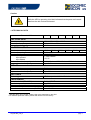
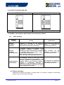
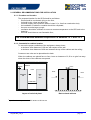
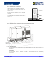
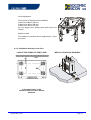
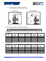
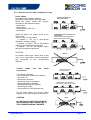
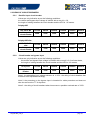
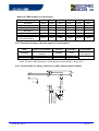
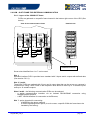
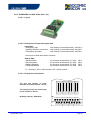
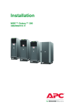
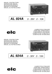
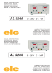
INSTALLATION MANUAL FOR DELPHYS MP and DELPHYS MP elite UNINTERRUPTIBLE POWER SYSTEMS UPS/NTA GB/DELMP_INS.B 06/02/2006 Certificate of Warranty The warranty conditions are stipulated in the sales contract, if not the following points shall apply. The manufacturer exclusively guarantees his own products against any defect in construction or operation arising from faulty design, materials or workmanship according to the conditions set down below. The manufacturer, at his discretion, is entitled to adapt his product in order to comply with the warranty or replace the faulty parts. The manufacturer’s warranty does not apply in the following cases: - Defects arising either from designs or parts imposed or supplied by the Purchaser. - Failure due to fortuitous circumstances or force majeure. - Replacements or repairs resulting from normal wear of units and machinery, - Damage or injuries caused by negligence, lack of inspection or maintenance, or improper use of the products. The period of validity of the warranty may never exceed 12 months after delivery. Replacements, repairs or modifications of parts during the warranty period cannot extend the duration of the warranty. For these stipulations to be valid, the Purchaser must, within a maximum of 8 days beyond which the warranty lapses, expressly inform the Manufacturer of the faulty design, or the material or manufacturing defect, stating in detail the grounds for his complaint. Defective parts replaced free of charge by the Manufacturer are to be put at his disposal, so that he may become the sole owner. The warranty legally ceases if the Purchaser has, of his own initiative, undertaken modifications or repairs on the Manufacturer’s products without the written consent of the latter. The Manufacturer’s liability is limited to the obligations as defined herein (repair or replacement), all other items of damage being formally excluded. The Purchaser is liable for taxes or duties of any kind in compliance with either the European regulations, or those of the country of import or transit. GB_DELMP_INS_B page 1/42 FOREWORD We thank you for the trust you have in Socomec Sicon’s Uninterruptible Power Systems. This equipment is fitted with up to date technology with power semiconductors (IGBT) including a digital micro-controller. Our equipment complies with standard IEC 62040-2 and IEC 62040-1-2. CAUTION : “This is a product for restricted sales distribution to informed partners. Installation restrictions or additional measures may be needed to prevent disturbances”. SAFETY REQUIREMENTS Using conditions: Do read carefully this manual and comply with the safety notes mentioned before using the UPS. Whatever the repairs, they must be made only by authorised staff, who have been suitably trained. It is recommended that the ambient temperature and the humidity of the UPS environment are maintained below the values specified by the manufacturer. This equipment meets the requirements of the European directives applied to this product. As a consequence it is labelled as follows: REGULATIONS CONCERNED WITH ENVIRONMENTAL ISSUES Recycling of electrical products and equipment. Provision is made in European countries to break up and recycle materials making up the system. The various components must be disposed of in accordance with the legal provisions in force in the country where the system is installed. Battery wastes Used batteries are considered as toxic wastes. It is therefore essential to entrust them solely and exclusively to firms specialised in their recycling. They can not be treated with other industrial or household wastes, as set out in local regulations in force. GB_DELMP_INS_B page 2 CONTENTS CHAPTER 1: GENERAL ...................................................................................................................................2 1.1 PURPOSE................................................................................................................................................2 1.2 POWER SUPPLY INPUTS ......................................................................................................................2 1.3 SAFETY NOTES ......................................................................................................................................2 1.4 TECHNICAL DATA ..................................................................................................................................2 1.5 LAYOUT OF DELPHYS MP UPS ............................................................................................................2 1.6 GENERAL PACKAGING CONDITIONS FOR UPS AND BATTERIES ...................................................2 1.6.1 UPS packaging .........................................................................................................................2 1.6.2 Battery packaging .....................................................................................................................2 CHAPTER 2: 2.1 2.2 GENERAL RECOMMENDATIONS FOR INSTALLATION ......................................................................2 2.1.1 Premises and location ..............................................................................................................2 2.1.2 Constraint for cabinet location ..................................................................................................2 2.1.3 Installation on a raised floor......................................................................................................2 2.1.4 DELPHYS MP on a raised floor with adjustable support frame ...............................................2 2.1.5 Adjustable frame .......................................................................................................................2 2.1.6 Installation directly on the floor .................................................................................................2 2.1.7 Ventilation and air conditioning constraints ..............................................................................2 HEAT LOSS AND VENTILATION CHARACTERISTICS.........................................................................2 2.2.1 General rules for cable installation on tray ...............................................................................2 CHAPTER 3: 3.1 GENERAL RECOMMANDATIONS FOR INSTALLATION ........................................................2 HANDLING ..................................................................................................................................2 3.2 DIMENSIONS AND WEIGHTS ................................................................................................................2 3.1.1 UPS cabinets and modular units for Delphys MP (parallel system). ........................................2 3.1.2 UPS cabinets and modular units for Delphys MP elite (parallel system). ................................2 3.1.3 Central bypass cabinet .............................................................................................................2 3.1.4 Bypass isolating transformer (for linear loads) .........................................................................2 3.1.5 Battery cabinets ........................................................................................................................2 HANDLING FROM ABOVE......................................................................................................................2 3.3 HANDLING FROM UNDERNEATH .........................................................................................................2 3.4 WEIGHT AND HANDLING OF BATTERY CABINETS............................................................................2 CHAPTER 4: 4.1 4.2 4.3 INSTALLATION AND CABINET POSITIONING........................................................................2 INSTALLATION........................................................................................................................................2 4.1.1 Cabinet positioning ...................................................................................................................2 4.1.2 Layout of power connections ....................................................................................................2 GENERAL RULES FOR CABINET ASSEMBLING .................................................................................2 4.2.1 Assembling of cabinets .............................................................................................................2 4.2.2 Fixing to a raised floor (or directly to the floor) .........................................................................2 BATTERY CABINETS..............................................................................................................................2 4.3.1 Safety........................................................................................................................................2 4.3.2 Protection of battery cabinets ...................................................................................................2 4.3.3 Cabinet fixing to the floor ..........................................................................................................2 4.3.4 Adjusting the fastening rod of auxiliary cabinets ......................................................................2 4.3.5 Replacement of batteries..........................................................................................................2 GB_DELMP_INS_B page 3 CHAPTER 5: 5.1 5.2 5.3 ELECTRICAL CONNECTIONS ..................................................................................................2 LOCATION AND DIMENSIONS OF TERMINALS...................................................................................2 5.1.1 Separated rectifier and bypass inputs on Delphys MP UPS ....................................................2 5.1.2 Separated rectifier and bypass inputs on Delphys MP elite UPS.............................................2 5.1.3 Common rectifier and bypass input ..........................................................................................2 5.1.4 characteristics of connection terminals.....................................................................................2 5.1.5 Connection to a neutral system of TNC type............................................................................2 5.1.6 Characteristics of connection terminals ....................................................................................2 5.1.7 Terminals for unit inputs on the bypass cabinet .......................................................................2 5.1.8 Terminals for utility input/load output on the bypass cabinet....................................................2 DESCRIPTION OF POSSIBLE UPS CONFIGURATIONS......................................................................2 5.7 EXTERNAL CONNECTIONS...................................................................................................................2 5.3.1 Grounding precautions .............................................................................................................2 5.3.2 Connecting earth cables ...........................................................................................................2 5.3.3 Earth cable cross-section .........................................................................................................2 5.3.4 Leakage current (rating of the differential protection)...............................................................2 5.3.5 Neutral cable cross-section ......................................................................................................2 VALUES OF CURRENTS FOR CABLE SIZING .....................................................................................2 5.4.1 Input rectifier currents for Delphys MP and Delphys MP elite ..................................................2 5.4.2 Battery currents at the end of the back up time........................................................................2 5.4.3 Mean current supplied by the battery when discharging ..........................................................2 5.4.4 Bypass current (or output current to the load) ..........................................................................2 SIZING OF CIRCUIT BREAKERS ...........................................................................................................2 5.5.1 Rectifier input circuit breaker ....................................................................................................2 5.5.2 Circuit breaker on bypass input ................................................................................................2 5.5.3 Circuit breaker on a common rectifier and bypass input ..........................................................2 5.5.4 Protection and cross-section of battery cables.........................................................................2 5.5.5 Protection of battery cables by means of circuit breakers ........................................................2 5.5.6 Circuit breaker for battery protection on UPS's between 60 and 200kVA................................2 COM - SLOT FRAME FOR EXTERNAL COMMUNICATION..................................................................2 5.6.1 Layout of the COM-SLOT frame...............................................................................................2 5.6.2 STANDARD and ADC PCBs (UIO – 0x)...................................................................................2 5.6.3 Layout .......................................................................................................................................2 5.6.4 Description of input and output data .........................................................................................2 5.6.5 Description of terminals ............................................................................................................2 5.6.6 Serial connection PCB (USL – 0x)............................................................................................2 5.6.7 Layout .......................................................................................................................................2 5.6.8 Description of connections........................................................................................................2 EMERGENCY STOP (ESD) ....................................................................................................................2 5.8 AUTOMATIC OPENING OF BATTERY PROTECTION Q20 ..................................................................2 5.9 GENERATOR SET OPERATION ............................................................................................................2 5.10 BACKFEED PROTECTION.....................................................................................................................2 5.4 5.5 5.6 Lexicon : UPS Module UPS unit CIM DC ADC ACS ESD : Uninterruptible Power Systems : set comprising a rectifier, a battery and an inverter in a central bypass system : set comprising a rectifier, a battery, an inverter and a bypass in a parallel modular system : Consulting, Inspection and Maintenance Department : Direct Current : Advanced Dry Contacts : Automatic Cross Synchronisation (optional for keeping the UPS synchronisation in specific conditions) : Emergency Switching Device (as per standards) GB_DELMP_INS_B page 4 CHAPTER 1: GENERAL GB_DELMP_INS_B page 5 1.1 PURPOSE This manual gives important information as regards safety, handling and connection of DELPHYS MP and DELPHYS MP elite UPS’s. 1.2 POWER SUPPLY INPUTS Three power supply inputs are needed to operate the system: - voltage on input 1 for the supply to the rectifier, - voltage on input 2 for the supply to the automatic bypass (depending on the system, inputs 1 and 2 can be common), - the DC voltage (about 500Vdc) for the battery. 1.3 SAFETY NOTES For the safety of personnel and equipment, do read very carefully this instruction manual. WARNING Take all precautions when handling the cabinets or the various components of the system, such as batteries. CAUTION Whatever the connections or the using and maintenance operations, they must be exclusively performed by authorised staff, who have been trained accordingly. CAUTION EMI filters inside the UPS induce high leakage currents. As a consequence, it is imperative to connect earth cables before any mains connection. CAUTION The equipment can only be switched on or used if the following conditions are fulfilled : - electrical connections comply with the regulation in force (earth bonding, appropriate protections and cross-section of cables) - all means to comply with the protection index of the system are in place, such as side panels, doors, glands, shields or whatever...). GB_DELMP_INS_B page 6 Caution While the UPS is operating, this label indicates that the parts are live and therefore the risk of electrical hazard. 1.4 TECHNICAL DATA Power in kVA 60 80 100 120 160 200 RECTIFIER INPUT Rated input voltage and max. tolerances 380V / 400V / 415V ± 10% 1 Rated input frequency and max. tolerances 50 Hz / 60 Hz ± 10% Input power factor > 0.93 INVERTER OUTPUT Rated output active power Rated output voltage Rated output frequency Max. frequency tolerances: input present input absent Maximum overload capacity admitted Inverter short-circuit capacity 48kW 64kW 80kW 96kW 380 V / 400 V / 415 V + N * 50 Hz / 60 Hz 128kW 160kW ± 2 Hz settable ± 0,2 % 110 % 60 min – 125 % 10 min – 150 % 1 min Up to 3.5 In BYPASS Maintenance bypass Maximum overload capacity admitted Bypass short-circuit capacity Built-in 110 % 60 min – 125 % 10 min – 150 % 1 min Up to 25 In BATTERIES Technology VRLA – open lead –Nickel Cadmium ENVIRONMENT Protection index (IEC 60529) Service temperature Recommended ambient temperature Relative humidity Acoustic noise measured at 1m (ISO3746) 1 2 IP 20 Æ IP 32 2 0 to 35°C 25°C 95 % max without condensation about 72 dBA 208-220-480V upon request. Please refer to the data label on the UPS For different protection index, please seek advice from the factory. GB_DELMP_INS_B page 7 1.5 LAYOUT OF DELPHYS MP UPS DELPHYS MP DELPHYS MP elite Width of the UPS cabinet alone: 800 mm Width of the UPS cabinet alone: 1000 mm 1.6 GENERAL PACKAGING CONDITIONS FOR UPS AND BATTERIES 1.6.1 UPS packaging Packaging category Packing Applications Standard BULLPACK packaging Equipment is protected by two layers of Road transport for domestic cellular plastic (or three for non-domestic market or forwarding to destinations) fastened with scotch tape. neighbouring countries. CPA-type packaging (cardboard pallet) At customer’s request and in addition to the BULLPACK two-layer protection, extra transport for UE packaging consists of fastening the equipment Road to a wooden pallet and to protect it with a countries or air freight for cardboard fixed to the pallet. worldwide destinations. Under specific request, a corrosion proofing barrier can replace the Bullpack protection. Packaging SEI 4C (called NEFAB) The packaging consists of crates with closed joints and physical-chemical protection. The corrosion protection is guaranteed by a VCI Sea transport for equipment wrapping (Vapour and Corrosion Inhibitor), that might be stored for an resistant to considerable difference in extended period of time. temperature and by the addition of desiccant bags. Unless otherwise requested, the storage period is limited to 12 months. 1.6.2 Battery packaging Batteries are delivered on pallets, in pallets-cases or mounted in cabinets. Avoid striking battery cells and connection terminals. GB_DELMP_INS_B page 8 CHAPTER 2: GENERAL RECOMMANDATIONS FOR INSTALLATION GB_DELMP_INS_B page 9 2.1 GENERAL RECOMMENDATIONS FOR INSTALLATION 2.1.1 Premises and location The proposed location for the UPS should be as follows: - there should be no obstacle lying on the floor, - it should be dry, clean and dust-free, - it should comply with a pollution index of class 2 (i.e. free from conductive dust) - the installation of cables or conduits should be completed, - the room must be large enough, - ventilation should be sufficient to ensure a constant temperature to the UPS and to the batteries. - the local should have a non-flammable floor, The recommended ambient temperature is between 15°C and 25°C 2.1.2 Constraint for cabinet location To ensure the proper ventilation of the equipment, always leave: - a minimum clear distance of 100 mm with respect to the wall - a minimum clear distance of 400 mm between the top of the cabinet and the ceiling. Comment: two units can be placed back to back When the cabinets are placed face to face, leave a clearance of 2,30 m to give free way3 when the doors of the cabinets are opened. 100mm > 400mm 100mm Front Front DELPHYS MP Front UPS or other UPS UPS > 2300 mm Layout of technical plant 3 Back to back cabinets Specifications as per standard IEC 60364 or NFC15100 GB_DELMP_INS_B page 10 2.1.3 Installation on a raised floor When for weight and space requirements, the UPS is installed on a specific base (Please see section 2.1.5). Provide cut-outs in the raised floor for adequate ventilation. Front face UPS For air flow and heat loss details, please refer to section 2.2 Fresh air flow Fresh air flow 2.1.4 DELPHYS MP on a raised floor with adjustable support frame Adjustable support frame 2.1.5 Adjustable frame The adjustable frame is designed to support DELPHYS MP & MP elite UPS's installed on a raised floor. Installation The adjustable frame is delivered as a kit to be assembled with the assembling instructions. GB_DELMP_INS_B page 11 Level adjustment M10 Three levels of adjustment are available: Frame from 280 to 445 mm, Frame from 420 to 560 mm, Frame from 530 to 670 mm. For any higher level, please seek advice from the factory. M10 M8 M8 Maximum load M10 The maximum load that can be supported is 1,5 ton per frame. M10 2.1.6 Installation directly on the floor LAYOUT FOR FIXING TO THE FLOOR INSTALLATION ON A RACEWAY WALL 4 elongated holes 13x15 clearance from the wall: 100mm minimum GB_DELMP_INS_B page 12 2.1.7 Ventilation and air conditioning constraints Please respect the layout instructions for air flow. VENTILATION AIR CONDITIONING WARM AIR AIR AirCONDITIONER conditioner WARM WARM AIR AIR COLD AIR COLD AIR COLD AIR 2.2 HEAT LOSS AND VENTILATION CHARACTERISTICS The recommended ambient temperature is between 15 and 25°C. DELPHYS MP POWER (kVA) 60 80 100 120 160 200 Bottom air flow (m3/h) 400 400 400 400 800 800 Door air flow (m3/h) Total air flow (m3/h) 900 900 1100 1100 1100 1100 1300 1300 1500 1500 1900 1900 Door air flow (m3/h) Total air flow (m3/h) 1600 1600 1600 1600 1600 1600 2000 2000 2000 2000 2400 2400 Heat loss at Pn - cos phi 0,8 (kW) 3 5,5 5,8 7,5 9,4 13,1 Heat loss at Pn (kcal/h) 2600 4800 5000 6500 8100 11300 Heat loss at Pn - cos phi 0,8 (kW) 5,4 6,5 7,7 8,6 10,2 15,4 Heat loss at Pn (kcal/h) 4700 5600 6700 7400 10300 13300 DELPHYS MP elite POWER (kVA) 60 80 100 120 160 200 GB_DELMP_INS_B Bottom air flow (m3/h) 400 400 400 400 800 800 page 13 2.2.1 General rules for cable installation on tray Power cables Connection to the system cabinets: All metallic cable trays must be grounded. Divide the power cables into groups, according to the different circuits : - mains input, - battery input, - connections to each unit, - load output. Gather all poles of a power circuit in the same group : - poles + and - for the battery, - 3 phases + PE for a three-phase distribution (rectifier supply), - 3 phases + neutral + PE for the bypass supply or the downstream distribution, - 3 phases + PE for the bypass supply through an isolation transformer. CORRECT INSTALLATION WITH PARTITIONING ADMISSIBLE INSTALLATION WITHOUT PARTITIONING Risk of electromagnetic disturbances between battery and load cables 10 cm mini. 10 cm mini. CAUTION : WRONG All metallic cable trays -either fixed to the wall or in a raised floor- must be grounded and connected to the corresponding cabinets. Control cables connections: and low power This category includes : - the connections between the cabinets and each unit, - the transfer of alarms, - the remote control connection, - the connections to the BMS (Building Management System), - the emergency stop, - the connection to the generator set. Do not place power and control cables together in the same tray and same group. CAUTION : CORRECT INSTALLATION WITH PARTITIONING ADMISSIBLE INSTALLATION WITHOUT PARTITIONING OF THE CONTROL CABLES 10 cm mini. 10 cm mini. 10 cm mini. WRONG ALL METALLIC CABLE TRAYS, MUST BE GROUNDED AND CONNECTED TO THE CORRESPONDING CABINETS. GB_DELMP_INS_B page 14 CHAPTER 3: HANDLING GB_DELMP_INS_B page 15 3.1 DIMENSIONS AND WEIGHTS The packed weight of each item is shown: - with paint on wooden crates, - with indelible felt pen on cellular plastics if standard packing is used. Weight can be over values specified if packing is specific or if options are provided. 3.1.1 UPS cabinets and modular units for Delphys MP (parallel system). POWER (kVA) WEIGHT MP (kg) WIDTH (mm) DEPTH (mm) - floor requirement 60-80 3-ph 650 100-120 3-ph 850 800 160 3-ph 200 3-ph 940 800 - overall dimensions with door handle 850 - door, handle and rear panel excluded HEIGHT (mm) 795 1930 3.1.2 UPS cabinets and modular units for Delphys MP elite (parallel system). POWER (kVA) WEIGHT MP elite (kg) WIDTH (mm) DEPTH (mm) - floor requirement 60-80 3-ph 700 100-120 3-ph 840 1000 160-200 3-ph 1000 800 - overall dimensions with door handle 850 - door, handle and rear panel excluded HEIGHT (mm) 795 1930 3.1.3 Central bypass cabinet POWER (kVA) WEIGHT (kg) WIDTH (mm) DEPTH (mm) - floor requirement - overall dimensions with door handle 500 3-ph 315 810 800 3-ph 420 1010 1200 3-ph 600 1310 815 815 815 845 845 845 - door, handle and rear panel excluded 800 800 800 HEIGHT (mm) 1930 1930 1950 Note 1: The central bypass cabinet of 800kVA allows cable input from the front. No rear or side access is required. Note 2: The central bypass cabinets of 500kVA and 1200kVA require either rear or side access for cable connection. GB_DELMP_INS_B page 16 3.1.4 Bypass isolating transformer (for linear loads) Note: for supplying non-linear loads, please seek advice from the factory. POWER (kVA) WEIGHT (kg) WIDTH (mm) DEPTH (mm) 80 3-ph 450 600 120 3-ph 550 600 - floor requirement 815 - overall dimensions with door handle 845 - door, handle and rear panel excluded 800 1930 HEIGHT (mm) 200 3-ph 850 800 3.1.5 Battery cabinets Note: the number of battery cabinets depends on the power of the UPS and the duration of the back up time. MAXIMUM WEIGHT FOR TRANSPORT (kg) Maximum weight per shelf (kg) Maximum weight with the 5 shelves (kg) WIDTH (mm) DEPTH (mm) - floor requirement 1250 300 1550 800 815 - Overall dimensions with door handle 845 - door, handle and rear panel excluded HEIGHT (mm) 800 1930 GB_DELMP_INS_B page 17 3.2 HANDLING FROM ABOVE For weight and dimensions of the UPS, please see section 3.1. Please, take into account the instructions provided for handling, so as to avoid damage to the equipment. THE USE OF STRAPS IS PROHIBITED IMPORTANT: THE CABINETS MUST BE KEPT IN AN UPRIGHT POSITION WHEN SHIPPED OR HANDLED. HANDLING BY USING SLINGS Slings can be used, provided that they are ≥ 1,5 meter-long. CAUTION : lift the cabinet up and down carefully and smoothly. NOTE : eye screws of M16 type with 30-mm inner diameter are supplied on request. Remove the screw or plastic part protecting the thread and insert the eye screws. In order to meet the protection index specified, do no forget to replace the screws or plastic parts after removing the eye screws. HANDLING BY USING A LIFTING BEAM If the height under ceiling does not allow the use of slings, it is preferable to use a lifting beam. GB_DELMP_INS_B page 18 3.3 HANDLING FROM UNDERNEATH Remove the grilles on the front and rear of the cabinet and introduce the fork under the unit. HANDLING FROM THE FRONT OR THE REAR Lateral handling is also possible, provided that the bottom side panels are removed. LATERAL HANDLING IMPORTANT GB_DELMP_INS_B Given the cabinets are heavy, handling using a pallet truck on slopes or ramps – even only slightly inclined, is hazardous and can cause severe accidents. Take all required precautions and use adapted means and tools. page 19 3.4 WEIGHT AND HANDLING OF BATTERY CABINETS WEIGHT Weight of empty cabinet: 65kg. The weight of the cabinet for transport, handling and positioning shall not exceed 1250 kg. If each shelf can support 300kg, the maximum weight of the cabinet installed on site shall not exceed 1550 kg, which means that one out of the 5 shelves shall support less than 300kg). HANDLING FROM UNDERNEATH Handling can be from the bottom using a lifting truck. Front, rear as well as side bottom panels are available on the top of the cabinet. HANDLING FROM ABOVE Handling can be by using 4 slings that are at least 1 meter long. The total weight shall not exceed 800 kg, i.e. 200 kg per eye screw, so please adapt to the weight to be lifted accordingly. NOTE Each battery cabinet has two side reinforcement bars. After unloading, they must be removed to ensure proper ventilation of battery blocks. If the cabinet is provided with side panels, they shall be removed first. For advice regarding safety, fixing to the floor of the cabinets and adjusting of fastening rods, please see section 4.3. Side bar Side bar GB_DELMP_INS_B page 20 CHAPTER 4: INSTALLATION AND CABINET POSITIONING GB_DELMP_INS_B page 21 4.1 INSTALLATION 4.1.1 Cabinet positioning To make transport and handling easier, the system is separated into cabinets (or cabinet sets). The 'X' symbol on the front face indicates the separation points between the cabinets. The individual cabinet position should correspond with sequence / numbers indicated on the front view of the system. (The number of each cabinet is indicated on the right top corner on the inside of the door). Note : reference should be made to the technical details in the drawing file. 4.1.2 Layout of power connections When assembling the cabinets, the "" symbols mentioned on the basic scheme indicate the power connections to be achieved. PE X10 X20 X40 X50 : earth bonding, : rectifier power input, : battery input, : bypass power input, : output to the load. Battery cabinet Delphys MP For connection arrangements, please see section 5.2. Note : reference should be made to the technical details of the drawing file. Note : For dimensions and designation of terminals and terminations, please see section 5.1. GB_DELMP_INS_B page 22 4.2 GENERAL RULES FOR CABINET ASSEMBLING 4.2.1 Assembling of cabinets Use tensilock screws - supplied by the manufacturer - to assemble the different cabinets. These are 'welded structure-type cabinets', meeting all requirements as regards electromagnetic compatibility. The tensilock screws bite into the paint and guarantee electric contact between the frame and the different cabinets. They also guarantee equipotential grounding. Notes: - 4.2.2 A rubber seal is placed between some of the cabinets to be assembled. If cabinets are placed against a wall, screw fixings located at the rear are not accessible; as a result only the screw on the top of the rear panel will be fixed. Fixing to a raised floor (or directly to the floor) Each foot of the cabinet needs to be linked up to the metallic mesh network (if the cabinet is on a raised floor) or to have direct earth bonding (if the cabinet is directly positioned on the floor) by using short links with a cross-section ≥ 35 mm². Use braidings to connect all the metallic feet of the raised floor and guarantee equipotential cabling. A = fixing to the floor (hole ∅ 13), B = screw THM 14 for level adjustment, C = fixing of braidings, D = fixing of the grille SEPARATED CABINETS Avoid spaces between cabinets. Connect the cabinets to each other by using a conductor with a crosssection ≥ 35 mm² and not exceeding a 20-meter length. An accessible and grounded metallic mesh network can also be a solution if every cabinet is connected to this network. GB_DELMP_INS_B page 23 4.3 BATTERY CABINETS NOTE: This page is relating to battery cabinets including sealed lead acid batteries (VRLA). In case of a cabinet with open lead acid batteries, specific precautions and conditions shall be undertaken as per standard IEC 62040-1-2, part N (ventilation of battery blocks). 4.3.1 4.3.2 Safety ELECTRICAL SAFETY For safety reasons during transports and handling, batteries are disconnected at the level of each rack (or by sections not exceeding 150 V). Take all necessary precautions when reconnecting the cables. MECHANICAL SAFETY For batteries on racks or in cabinets, the cabinet must be fixed to the floor to prevent it from falling over. Each cabinet is fitted with pre-drilled feet See dimensions below. CAUTION Connection must be performed by authorised staff, which have been previously trained. Connections to be performed are : - grounding of battery cabinet, - polarities + and – to the inverter, - between battery sections and/or between shelves. Protection of battery cabinets The protection of the battery cabinet is located in either a specific enclosure or cabinet. 4.3.3 Cabinet fixing to the floor FEET OF BATTERY CABINET Each foot has a floor fixing hole (labelled A : ∅ 13) and a welded nut for level adjusting (labelled B : screw THM12 not supplied). A B CAUTION : When the battery cabinet is installed, cut and remove the plastic fastening of battery cells in order to release the safety valve. GB_DELMP_INS_B page 24 4.3.4 Adjusting the fastening rod of auxiliary cabinets Adjust part marked "A" to your needs in order to adapt the insert of the fastening rod. 4.3.5 Replacement of batteries ADVICE When replacing the batteries, use the same type and number of battery blocks. Do not dispose of into a fire due to risk of explosion. CAUTION GB_DELMP_INS_B Do not try to open or break up batteries. The electrolyte is toxic and may cause acid projections or injuries. page 25 CHAPTER 5: ELECTRICAL CONNECTIONS GB_DELMP_INS_B page 26 5.1 LOCATION AND DIMENSIONS OF TERMINALS ELECTRICAL SAFETY 5.1.1 To ensure proper tightening of lugs to terminations, use screws supplied by SOCOMEC-SICON (or screws and washers of section adapted to the holes of terminations). Separated rectifier and bypass inputs on Delphys MP UPS DELPHYS MP without switch Q1 ELECTRICAL SAFETY As switch Q1 is not provided in the UPS, a switching device with quick access must be installed in the cabling system of the building. DELPHYS MP with switch Q1 (optional) For more details about the connection terminals, please refer to section 5.1.4). GB_DELMP_INS_B page 27 5.1.2 Separated rectifier and bypass inputs on Delphys MP elite UPS DELPHYS MP elite without switch Q1 ELECTRICAL SAFETY As switch Q1 is not provided in the UPS, a switching device with quick access must be installed in the cabling system of the building. DELPHYS MP elite with switch Q1 (optional) For more details about the connection terminals, please refer to section 5.1.4). GB_DELMP_INS_B page 28 5.1.3 Common rectifier and bypass input With a common rectifier and bypass input, straps marked A are to be used for L1, L2 and L3 in order to ensure rectifier input connection. Common input system DELPHYS MP DELPHYS MP elite 5.1.4 Characteristics of connection terminals PE : X10 : X20 : X40 : X50 : GB_DELMP_INS_B Copper termination 40x5mm, 1 hole φ11, screw M10. Rectifier supply input Copper termination 63x4mm, 2 holes φ11, screw M10, max cross section 2x120 mm². Battery input L+ and L-, Copper termination 40x5mm, 1 hole φ11, screw M10, max cross section 2x240 mm². bypass supply input Copper termination 63x4mm, 2 holes φ11, screw M10, max cross section 2x120 mm². load output Copper termination 63x4mm, 2 holes φ 11, screw M10, max cross section 2x120 mm². page 29 5.1.5 Connection to a neutral system of TNC type DELPHYS MP DELPHYS MP elite 5.1.6 Characteristics of connection terminals PE : X10 : X20 : X40 : X50 : GB_DELMP_INS_B Copper termination 40x5mm, 1 hole φ11, screw M10. Rectifier supply input Copper termination 63x4mm, 2 holes φ11, screw M10, max cross section 2x120 mm². Battery input L+ and L-, Copper termination 40x5mm, 1 hole φ11, screw M10, max cross section 2x240 mm². bypass supply input Copper termination 63x4mm, 2 holes φ11, screw M10, max cross section 2x120 mm². load output Copper termination 63x4mm, 2 holes φ 11, screw M10, max cross section 2x120 mm². page 30 5.1.7 POWER (kVA) UNIT INPUTS 500 600 to 800 3-ph 900 to 1200 3-ph X45 X45 X45 5.1.8 4 Terminals for unit inputs on the bypass cabinet Dimensions of terminals Terminations in Cu 40x6, 8 holes ∅11, screw M10 Terminations in Cu 100x5, 3 holes ∅13, screw M12 Terminations in Cu 100x10, 6 holes ∅13, screw M12 Terminals for utility input/load output on the bypass cabinet POWER (kVA) UNIT INPUTS 500 3-ph X40 and X50 800 3-ph 1200 3-ph X40 and X50 X40 and X50 Dimensions of terminals Neutral: 50x10 Cu, 1 hole ∅13 screw M12 Phase: 40x6 Cu, 1 hole ∅13 screw M12 Terminations in Cu 100x5, 3 holes ∅13, screw M12 Terminations in Cu 4 100x10, 6 holes ∅13, screw M12 Extension terminals (100x10 Cu, 7 holes ∅13) are to be moved from X40 to X50 if cable input is from the top. GB_DELMP_INS_B page 31 5.2 DESCRIPTION OF POSSIBLE UPS CONFIGURATIONS STANDARD UPS WITH NON ISOLATED RECTIFIER X10 = RECTIFIER INPUT X20 = BATTERY CONNECTION X40 = BYPASS INPUT X50 = OUTPUT TO THE LOAD STANDARD UPS WITH NON ISOLATED RECTIFIER AND BYPASS TRANSFORMER X10 X20 X500 X50 = RECTIFIER INPUT = BATTERY CONNECTION = BYPASS INPUT = OUTPUT TO THE LOAD STANDARD UPS WITH ISOLATED RECTIFIER X10 = RECTIFIER INPUT T10 ABC = primary transfo T13 L10 ABC = secondary transfo T13 X20 = BATTERY CONNECTION X40 = BYPASS INPUT X50 = OUTPUT TO THE LOAD STANDARD UPS WITH ISOLATED RECTIFIER AND BYPASS TRANSFORMER X10 = RECTIFIER INPUT T10 ABC = primary transfo T13 L10 ABC = secondary transfo T13 X20 = BATTERY CONNECTION X500 = BYPASS INPUT X50 = OUTPUT TO THE LOAD GB_DELMP_INS_B page 32 5.3 EXTERNAL CONNECTIONS External connections are: - grounding connection, - rectifier and bypass connections, - load output, - emergency stop and transfer of alarms. STANDARD COMPLIANCE 5.3.1 To avoid injuries to people or damage to the equipment during functioning, cabling specifications, installation and sizing must comply with the domestic regulations in force. Grounding precautions UPS’s manufactured by SOCOMEC SICON UPS are designed for any grounding systems and are compatible with IT, TNS, TT neutral arrangements. When the neutral arrangement is of TNC type, the equipment must have a PEN conductor. In cases of different neutral systems between the utility and the load, a transformer must be installed at the bypass input to carry out isolation. 5.3.2 Connecting earth cables IMPORTANT : due to EMI filters*, there are "HIGH LEAKAGE CURRENTS". As a consequence, it is imperative to connect earth cables before mains cables. * EMI filters = protection against electromagnetic disturbances. 5.3.3 Earth cable cross-section The earth cable cross section must comply with the domestic regulations in force. 5.3.4 Leakage current (rating of the differential protection) The minimum differential current recommended is 300 mA. 5.3.5 Neutral cable cross-section It is necessary to check: a) the minimum cross-section of the neutral cable must equal one of the phase conductors. It is recommended to double the neutral conductor cross-section for supplying nonlinear loads as soon as: Icrest per phase / I r.m.s. per phase > 2,2. b) the balancing of the loads across the three phases, c) the values that will trip the protective devices. GB_DELMP_INS_B page 33 5.4 VALUES OF CURRENTS FOR CABLE SIZING NOTE : these values are only indicative for standard systems. 5.4.1 Input rectifier currents for Delphys MP and Delphys MP elite Operating conditions are as follows: - Input/output power supply voltage 3x400V, - The UPS is operating at rated power and batteries are recharging. 5.4.2 POWER on UPS output (kVA) DELPHYS MP Max. rectifier input current (A) DELPHYS MP elite Max. rectifier input current (A) 60 kVA 3-phase 80 kVA 3-phase 100 kVA 3-phase 120 kVA 3-phase 160 kVA 3-phase 200 kVA 3-phase 134 169 213 252 339 419 86 114 142 177 228 282 Battery currents at the end of the back up time The UPS is operating at rated power. 5.4.3 UPS Power 60kVA 80kVA 100kVA 120kVA 160kVA 200kVA Currents (A) 167 225 277 334 445 556 Mean current supplied by the battery when discharging The mean current value is to be taken into account for sizing connecting cables between the battery and the UPS. 5.4.4 UPS Power 60kVA 80kVA 100kVA 120kVA 160kVA 200kVA Currents (A) 154 205 255 307 408 505 Bypass current (or output current to the load) Operating conditions are as follows: - input/output power supply voltage 3x400V, - The UPS is operating at rated power. UPS Power 60 kVA 80kVA 100kVA 120kVA 160kVA 200kVA Currents (A) 87 116 144 174 232 290 Note: sizing of cables and protections upstream of the bypass shall take into account: overloads caused by non-linear loads, possible overloads admitted by the UPS i.e. 1,1In for 1h, 1,25In for 10min or 1,5In for 1min. GB_DELMP_INS_B page 34 5.5 SIZING OF CIRCUIT BREAKERS 5.5.1 Rectifier input circuit breaker Values are only indicative as per the following conditions: the rectifier and bypass input voltage is 3x400V with a cos phi = 0,8, the length of cabling between the circuit breaker and the UPS is <10 metres. Delphys MP DELPHYS MP 60 kVA 80kVA 100kVA 120kVA 160kVA 200kVA Sizing of circuit breaker 200A 200A 250A 400A 400A 630A 60 kVA 80kVA 100kVA 120kVA 160kVA 200kVA 100A 125A 160A 200A 250A 400A Delphys MP elite DELPHYS MP elite Sizing of circuit breaker 5.5.2 Circuit breaker on bypass input Values are only indicative as per the following conditions: - the rectifier and bypass input voltage is 3x400V with a cos phi = 0,8 on linear loads, - the length of cabling between the circuit breaker and the UPS is <10 metres. UPS power 60 kVA 80kVA 100kVA 120kVA 160kVA 200kVA Sizing of circuit breaker 125A 160A 200A 250A 400A 400A Note 1: the admissible input voltage tolerance is +/-10% - the sizing of circuit breakers has therefore to be adjusted accordingly. Note 2: the protection on the bypass input is intended for cable protection and does not take into account the I2T of thyristors. Note 3 : the sizing of circuit breakers takes into account a possible overload rate of 125%. GB_DELMP_INS_B page 35 5.5.3 Circuit breaker on a common rectifier and bypass input Values are only indicative as per the following conditions: - the rectifier and bypass input voltage is 3x400V with a cos phi = 0,8, - the length of cabling between the circuit breaker and the UPS is <10 metres. Delphys MP DELPHYS MP 60 kVA 80kVA 100kVA 120kVA 160kVA 200kVA Sizing of circuit breaker 200A 200A 250A 400A 400A 630A 60 kVA 80kVA 100kVA 120kVA 160kVA 200kVA 125A 160A 200A 250A 400A 400A Delphys MP elite DELPHYS MP elite Sizing of circuit breaker Note: the admissible input voltage tolerance is +/-10% - the sizing of circuit breakers has therefore to be adjusted accordingly. 5.5.4 Protection and cross-section of battery cables Values are provided for a distance of 20 meters between the UPS and the battery. (Battery mean current while discharging – Please see section 5.4.3). Use double insulated cables BN4-F. BACK UP TIME lower than 30 minutes UPS power (kVA) Protection FUSERBLOC DIN 43620 Sizing of fuses gG Protection FUSOMAT DIN 43620 Sizing of fuses gG Min. cross-section of cabling for a 20 meter distance GB_DELMP_INS_B 60 kVA 80 kVA 100 kVA 120 kVA 160 kVA 200 kVA Size 2 Size 2 Size 2 Size 2 Size 2 Size 2 160A T2 160A T2 200A T2 250A T2 400A T2 400A T2 Size 1 Size 1 Size 1 Size 1 Size 2 Size 2 160A T1 160A T1 200A T1 250A T1 400A T2 400A T2 35mm² 70mm² 95mm² 95mm² 150mm² 185mm² page 36 BACK UP TIME between 30 to 60 minutes UPS power (kVA) Protection FUSERBLOC DIN 43620 Sizing of fuses gG Protection FUSOMAT DIN 43620 Sizing of fuses gG Min. cross-section of cabling for a 20 meter distance 60 kVA 80 kVA 100 kVA 120 kVA 160 kVA 200 kVA Size 2 Size 2 Size 2 Size 2 Size 3 Size 3 160A T2 200A T2 250A T2 400A T2 500A T3 500A T3 Size 1 Size 1 Size 1 Size 2 Size 3 Size 3 160A T1 200A T1 250A T1 400A T2 500A T3 500A T3 35mm² 70mm² 95mm² 95mm² 150mm² 185mm² 5.5.5 Protection of battery cables by means of circuit breakers UPS power (kVA) Type of circuit breaker NS250 N FPAV 3P TM200D NS400 H FPAV 3P MP1 NS630 H FPAV 3P MP1 60 and 80 100 and 120 160 and 200 Ref. Socomec Ref Jeumont Schneider A035808 31631 A035788 A035798 32742 32942 Setting of circuit breaker At least thermal and magnetic 800A Note : be careful about the way of connecting the circuit breakers – See § 5.5.6. 5.5.6 Circuit breaker for battery protection on UPS's between 60 and 200kVA X20+ BAT X20- Q20 F18 14/51 10A Q20 Q20 X19/1 X19/2 X19/3 F19 14/51 10A F18 MX X19/4 GB_DELMP_INS_B DU 612.10 XB1/6 UIO-01 XB1/16 DU 612.10 XB1/5 UIO-01 XB1/17 K20 page 37 5.6 COM - SLOT FRAME FOR EXTERNAL COMMUNICATION 5.6.1 Layout of the COM-SLOT frame PCB’s are gathered on a specific frame located in the bottom right corner of the UPS (See below). View of the communication frame Q3 Q5 Detailed view 7 6 5 4 L1 L1 L2 N X40 L3 L2 3 2 L3 1 N X50 F82 F83 FRAME including COMMUNICATION PCBs Seven slots identified from 1 to 7 can be used. Slot 1: Standard interface PCB is provided as a standard with 3 inputs and 4 outputs with defined data (See section 5.6.2.1). Slot 2, 3 and 4: These ADC PCBs are optional with 3 input and 4 output data that can be set as per customer’s requirements. Using 3 ADC PCBs in the respective slots allows to have up to 9 settable inputs and up to 12 settable outputs. Slots 5 and 6 : the following communication PCBs can be selected: - a series communication interface via an isolated RS232/RS485 connection using MODBUS/JBUS protocol - a NET VISION interface for connection to the Ethernet, Slot 7 : option intended for connecting: - a MODEM to the phone network - a remote signalling/control panel (In such a case, a specific COM slot frame has to be installed by the factory). GB_DELMP_INS_B page 38 5.6.2 STANDARD and ADC PCBs (UIO – 0x) 5.6.2.1 Layout 5.6.2.2 Description of input and output data Input data : - Emergency stop - Opening of battery connection - Emergency generator loop closing on terminations IN1- and IN1+*, loop closing on terminations IN2- and IN2+, loop closing on terminations IN3- and IN3+. * dual input to allow the transfer of alarms. Output data : - General Alarm - Servicing alarm - Battery operation - LOAD ON MAINS dry contacts, terminations C1 dry contacts, terminations C2 dry contacts, terminations C3 dry contacts, terminations C4 NO1 NO2 NO3 NO4 NC1* NC2* NC3* NC4* * C = Common ; NO = make contact ; NC = break contact. 5.6.2.3 Description of terminals The wire size capacity of screw terminals is between 0,5 and 1,5 mm2 The emergency stop has a dual input for the transfer of alarms. Breaking capacity : 8A/230Vac. XB1 C2 NO2 NC2 IN1- IN1+ IN3- IN3+ C3 NO3 NC3 2 OUT 1 GB_DELMP_INS_B 3 OUT 4 C1 NO1 NC1 IN1- IN1+ IN2- IN2+ C4 NO4 NC4 page 39 5.6.3 Serial connection PCB (USL – 0x) 5.6.3.1 Layout 5.6.3.2 Description of connections RS232 XC2 : female DB9 standard connector of PC type. RS485 isolated XB1 : RTX+ and RTX- RS422 isolated XB1 : RTX+ for 'Transmit +' RTX- for 'Transmit –' RX+ RX- LEDs VL1 and VL3 provide information about the reception and transmission steps. LED VL2 indicates whether there is voltage or not. 5.7 EMERGENCY STOP (ESD) The UPS emergency stop causes: - the load to be shutdown - the rectifier and inverter to be shutdown while the battery remains connected. However, the battery connection can be made open on request, through the addition of a Mx coil, directly controlled by the emergency stop (Please, see following sections). Single UPS (Standard PCB) The emergency stop is carried out through the closing of the loop on terminations IN- and IN+. Dual input is provided to ensure the transfer of alarms. Opening of the loop can be set at commissioning. Modular systems Each unit is fitted with a COM SLOT frame including a standard PCB. The emergency stop can either control each unit separately or the whole system, provided that each loop is galvanically separated. GB_DELMP_INS_B page 40 Central bypass systems The central bypass cabinet incorporates a COM-SLOT frame including a standard PCB. The emergency stop can control : - only the central bypass cabinet (standard PCB – terminations IN1- and IN1+), - the whole system, provided that galvanic isolation is carried out between each loop. 5.8 AUTOMATIC OPENING OF BATTERY PROTECTION Q20 Opening of Q20 is controlled through loop closing on terminations IN2- and IN2+ of the standard PCB. This option enables Q20 to be opened following an emergency shutdown or a slow discharge. Battery cabinet/enclosure Connection inside the UPS STANDARD PCB 5.9 GENERATOR SET OPERATION A so-called GENERATOR SET information allows the UPS to operate according to gen set conditions. The manufacturer can set three conditions for generator set operation, that is: a) output voltage of charger(s) adjusted to the off-load voltage of the batteries. In such a case, the corresponding input is on terminations IN3- and IN3+ of the standard PCB, b) desynchronisation of the inverter from the bypass input and bypass locked, thus no transfer to the bypass mains is possible, Case of a modular system : each unit has to be connected to terminations IN3- and IN3+ of the standard PCB, Case of a central bypass system : the input is in the central bypass cabinet and has to be connected to terminations IN3- and IN3+ of the standard PCB. This data is transmitted via the internal bus to each module, that can individually be adjusted to a different off-load voltage. c) function a) and function b) through contact combination. NOTE GB_DELMP_INS_B Without a specific request, the factory standard setting implies there is no action on the UPS when the generator set is operating. Configurations mentioned above can be set at commissioning page 41 5.10 BACKFEED PROTECTION Standard: The Backfeed protection is compliant with standard IEC 62040-1-2. Purpose: The Backfeed protection is for ensuring personnel safety against any risks of accidental energy return to the input circuit. The Backfeed protection imposes the automatic opening of an switching device in case of a malfunctioning of the static switch. Principe : The Backfeed protection consists of an electronic detection PCB internal to the UPS and an external electromechanical device for isolation from the power circuit. Optionally, the back-feed protection device may be built into the system. For further details about the size of the protective device, please see sections 5.5.1 or 5.5.2. Label: A safety label bearing the following advice is available in this manual: «ISOLATE THE UPS BEFORE WORKING ON THIS CIRCUIT» The operator shall stick the label on the electromechanical device for isolation from the power circuit. Basic scheme PCB DU612 XB5 Backfeed Q82 XB6 XC17 XC16 Auxiliairy contact of the switching protection To the trip coil On PCB DU612: XB6 terminals 1-2 : connection of the trip coil 220V240V of the power isolating device. XB5 terminals 1-2: connection of the auxiliary contact indicating the status of the power isolating device. GB_DELMP_INS_B page 42