1
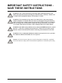
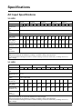
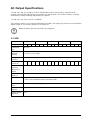
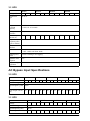
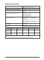
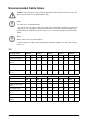
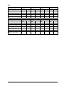
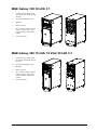
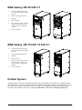
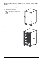
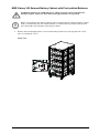
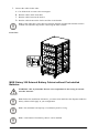
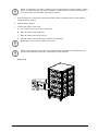
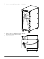
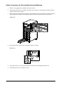
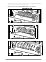
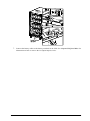
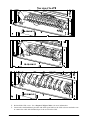
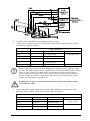
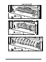
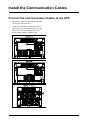
Installation
MGE™ Galaxy™ 300
380/400/415 V
American Power Conversion Legal Disclaimer
The information presented in this manual is not warranted by the American Power Conversion
Corporation to be authoritative, error free, or complete. This publication is not meant to be a
substitute for a detailed operational and site specific development plan. Therefore, American
Power Conversion Corporation assumes no liability for damages, violations of codes, improper
installation, system failures, or any other problems that could arise based on the use of this
Publication.
The information contained in this Publication is provided as is and has been prepared solely
for the purpose of evaluating data center design and construction. This Publication has been
compiled in good faith by American Power Conversion Corporation. However, no presentation
or warranty, either express or implied, is made as to the completeness or accuracy of the
information this Publication contains.
IN NO EVENT SHALL AMERICAN POWER CONVERSION CORPORATION BE
LIABLE FOR ANY DIRECT, INDIRECT, CONSEQUENTIAL, PUNITIVE, SPECIAL, OR
INCIDENTAL DAMAGES (INCLUDING, WITHOUT LIMITATION, DAMAGES FOR
LOSS OF BUSINESS, CONTRACT, REVENUE, DATA, INFORMATION, OR BUSINESS
INTERRUPTION) RESULTING FROM, ARISING OUT OF, OR IN CONNECTION WITH
THE USE OF, OR INABILITY TO USE THIS PUBLICATION OR THE CONTENT, EVEN IF
AMERICAN POWER CONVERSION CORPORATION HAS BEEN EXPRESSLY ADVISED
OF THE POSSIBILITY OF SUCH DAMAGES. AMERICAN POWER CONVERSION
CORPORATION RESERVES THE RIGHT TO MAKE CHANGES OR UPDATES WITH
RESPECT TO OR IN THE CONTENT OF THE PUBLICATION OR THE FORMAT
THEREOF AT ANY TIME WITHOUT NOTICE.
Copyright, intellectual, and all other proprietary rights of the content (including but not limited
to software, audio, video, text, and photographs) rests with American Power Conversion
Corporation or its licensors. All rights in the content not expressly granted herein are reserved.
No rights of any kind are licensed or assigned or shall otherwise pass to persons accessing
this information.
This Publication shall not be for resale in whole or in part.
Table of Contents
IMPORTANT SAFETY INSTRUCTIONS - SAVE THESE
INSTRUCTIONS ............................................................................................................... 1
Specifications ................................................................................................................... 2
AC Input Specifications.............................................................................................. 2
AC Output Specifications .......................................................................................... 3
AC Bypass Input Specifications .............................................................................. 4
Battery Specifications ................................................................................................ 5
Recommended Cable Sizes ...................................................................................... 6
Current Protection and Discrimination .................................................................. 8
Recommended Upstream Discrimination .................................................................. 8
Recommended Downstream Discrimination.............................................................. 9
Torque Specifications ................................................................................................. 9
Overview: MGE™ Galaxy™ 300 UPS Systems .............................................10
MGE Galaxy 300 30 kVA/ 40 kVA 3:3 ......................................................................10
MGE Galaxy 300 30 kVA 3:1 ......................................................................................11
MGE Galaxy 300 10 kVA/ 15 kVA/ 20 kVA 3:3........................................................11
MGE Galaxy 300 20 kVA 3:1 ......................................................................................12
MGE Galaxy 300 10 kVA/ 15 kVA 3:1 .......................................................................12
Parallel System .............................................................................................................12
Overview: MGE™ Galaxy™ 300 External Battery Cabinet .....................13
Before Installation ..........................................................................................................14
Space Considerations ................................................................................................14
Floor Anchoring (Optional) .......................................................................................15
Method 1: Unlimited Space Available ........................................................................15
Method 2: Limited Space Available ...........................................................................16
Prepare UPS for Cables..............................................................................................17
Prepare MGE Galaxy 300 External Battery Cabinet for Cables .......................18
MGE Galaxy 300 External Battery Cabinet with Pre-Installed Batteries .....................19
MGE Galaxy 300 External Battery Cabinet without Pre-Installed Batteries ................20
990–3618E-001
MGE™ Galaxy™ 300 380/400/415 V Installation
i
Connect the Power Cables........................................................................................22
Connect the UPS AC Cables .....................................................................................22
Install Battery Solution ................................................................................................25
Install the Internal Batteries in the MGE Galaxy 300 UPS.................................25
Cable Connection of Pre-Installed Internal Batteries .................................................28
Cable Connection of Not Pre-Installed Internal Batteries...........................................29
Install the MGE Galaxy 300 External Battery Cabinet ........................................30
Install and Connect the MGE Galaxy 300 External Battery Cabinet to a
Running UPS .................................................................................................................32
Install and Connect Cables to Third-Party External Battery Solution ...........36
Install the Communication Cables........................................................................40
Connect the Communication Cables to the UPS ................................................40
Connect the EPO Cable to the UPS ........................................................................42
Connect the Optional Signal Cables.......................................................................43
Connect External Battery Temperature (ATIZ) and External Battery
Breaker Signal between the UPS and the MGE Galaxy 300 External
Battery Cabinet .............................................................................................................44
Checklist after Installation ........................................................................................46
UPS ..................................................................................................................................46
External Battery Solution...........................................................................................46
ii
MGE™ Galaxy™ 300 380/400/415 V Installation
990–3618E-001
IMPORTANT SAFETY INSTRUCTIONS SAVE THESE INSTRUCTIONS
WARNING: ALL safety instructions in the Safety Sheet (990-3620) must be read,
understood and followed when installing the UPS and battery cabinet(s). Failure to do
so could result in equipment damage, serious injury, or death.
WARNING: The maximum storage time of the MGE Galaxy 300 external battery
cabinet is limited to six months due to the need of recharging the integrated batteries.
If the external battery cabinet remains de-energized for a long period, we recommend
that you energize the external battery cabinet for a period of 24 hours, at least once
every month. This charges the battery, thus avoiding possible irreversible damage.
WARNING: The MGE Galaxy 300 UPS can be used with EITHER internal or external
batteries. A UPS unit containing internal batteries CANNOT be used with external
batteries. Remove internal batteries before connecting external batteries to the UPS.
WARNING: The recommended minimum residual current protection is 3A, provided
the conditions defined in IEC60364.4-41 are respected.
Caution: All electrical power and power control wiring must be installed by a qualified
electrician and must comply with local and national regulations for maximum power rating.
990–3618E-001
MGE™ Galaxy™ 300 380/400/415 V Installation
1
Specifications
AC Input Specifications
3:3 UPS
10 kVA
15 kVA
20 kVA
30 kVA
40 kVA
Voltage
380 400 415 380 400 415 380 400 415 380 400 415 380 400 415
Connection
type
3P+N+G
Input frequency 45–65
(Hz)
THDI
< 9% at full load
Nom input
current (A)1
13
Max input
current (A)2
12.5 12
20
26
25
24
39.5 38
15.5 15
14.5 22.5 21.5 20.5 29
28
27
Input current
limitation (A)3
17.5 17
16
31
30
Input power
factor
correction
> 0.97 at load > 50%
25
19
24
18
22.5 32
36
53
50
48
42
40.5 38.5 56
53
51
47
45
59
56
42.5 61
1
Input current based on rated load and batteries fully charged.
Input current based on full battery recharge, nominal voltage, and rated load.
3 Current limitation through electronic current limiting is based on full battery recharge and -15%
input voltage.
2
3:1 UPS
10 kVA
Voltage
380
Connection
type
3P+N+G
15 kVA
400
415
20 kVA
30 kVA
380
400
415
380
400
415
380
400
415
Input frequency 45–65
(Hz)
THDI
< 9% at full load
Nom input
current (A)1
13
12.5
12
20
19
18
26
25
24
40
38
36
Max input
current (A)2
15.5
15
14.5
23
22
21
29
28
27
42
40
39
Input current
limitation (A)3
17.5
17
16
25
24
23
32
31
30
47
45
43
Input power
factor
correction
> 0.97 at load > 50%
1
Input current based on rated load and batteries fully charged.
Input current based on full battery recharge, nominal voltage, and rated load.
3 Current limitation through electronic current limiting is based on full battery recharge and -15%
input voltage.
2
2
MGE™ Galaxy™ 300 380/400/415 V Installation
990–3618E-001
AC Output Specifications
3:3 UPS: 380, 400, 415 V (400 V 50 Hz is standard but 60 Hz is also possible). Operation at 415
V/60 Hz is not possible and does not correspond to any known needs. For all other voltages or voltage
combinations, voltage-matching transformers are required.
3:1 UPS: 220, 230, 240 V (230 V is standard).
The operating voltage is set via the personalization procedures. The setting may result in an overload if the
output voltage is +3% and the current is at its rated level.
Note: In battery operation overload is not supported.
3:3 UPS
10 kVA
15 kVA
20 kVA
30 kVA
40 kVA
Voltage (V)
380 400 415 380 400 415 380 400 415 380 400 415 380 400 415
Connection
type
3P+N+G
Output
overload
capacity
<=125% for 2 minutes
<=150% for 10 seconds
Voltage
tolerance
±2%
Nom. output
current (A)
15
Output
frequency
(Hz)(sync to
mains)
50/60
Slew rate
(Hz/Sec)
2
THDU
< 3.0% linear loads
< 5.0%. 100% unbalanced 100% non-linear loads
Output power
factor
From 0.5 leading to 0.5 lagging.
Dynamic load
response
±5%
Output voltage
regulation
±2%
990–3618E-001
14.5 14
23
22
21
30
29
27
45
MGE™ Galaxy™ 300 380/400/415 V Installation
43
41.5 60
58
55
3
3:1 UPS
10 kVA
15 kVA
Voltage (V)
220
Connection
type
1P+N+G
Output
overload
capacity
<=125% for 2 minutes
<=150% for 10 seconds
Voltage
tolerance
±2%
Nom. output
current (A)
45
Output
frequency (Hz)
(sync to mains)
50/60
Slew rate
(Hz/Sec)
2
THDU
< 3.0% linear loads
< 5.0%. 100% non-linear loads
Output power
factor
From 0.5 leading to 0.5 lagging.
Dynamic load
response
±5%
Output voltage
regulation
±2%
230
43
240
42
220
68
20 kVA
30 kVA
230
240
220
230
240
220
230
240
65
62
90
87
83
136
130
125
AC Bypass Input Specifications
3:3 UPS
10 kVA
15 kVA
20 kVA
30 kVA
40 kVA
Voltage
380 400 415 380 400 415 380 400 415 380 400 415 380 400 415
Connection type
3P+N+G
Input frequency (Hz) 50/60
Nom output current
(A)
15
14.5 14
23
22
21
30
29
27
45
43
41.5 60
58
55
3:1 UPS
10 kVA
Voltage
220
Connection type
1P+N+G
Input frequency (Hz)
50/60
Nom output current (A)
45
4
230
15 kVA
240
220
43.5 41.5 68
20 kVA
30 kVA
230
240
220
230
240
220
230
240
65
62
90
87
83
136
130
125
MGE™ Galaxy™ 300 380/400/415 V Installation
990–3618E-001
Battery Specifications
Type
Maintenance-free sealed Lead-Acid battery with
suspended electrolyte: leakproof
Nominal voltage (16 blocks/15 blocks) (VDC)
± 192/±180
Float voltage (16 blocks/15 blocks) (VDC)
± 218/±204
End of discharge voltage (VDC)
± 158/±148 (May be higher than this at less than
full load)
Max. charging power for CLA version (may drop
to lower values at low AC mains)
10 kVA/ 8 kW: 3052 W
15 kVA/ 12 kW: 3052 W
20 kVA/ 16 kW: 3052 W
30 kVA / 24 kW: 6104 W
40 kVA/ 32 kW: 6104 W
Typical re-charge time
Internal charger: (for integrated battery
configuration)
10 hours - to 90% ±5% capacity after full discharge
at min. Config.
CLA: (for external battery configuration)
24 hours - to 90% ±5% capacity after full discharge
at min. Config.
Nom voltage (V)
12 V/block
End voltage (V)
9.9 V/block (varies from 11.4 V to 9.9 V
corresponding to load percentage from low to high)
kVA rating
10
15
20
30
40
INom
discharge1(A)
(15 blocks)
25
37
50
74
99
IMax
discharge2(A)
(15 blocks)
30
45
60
90
120
1
Nominal battery discharge current based on rated load and nominal battery voltage.
2
Maximum battery discharge current based on rated load at the end of the discharge
990–3618E-001
MGE™ Galaxy™ 300 380/400/415 V Installation
5
Recommended Cable Sizes
Caution: All wiring must comply with all applicable national and/or electrical codes. The
below specifications are recommendations only.
Note:
AC cable sizes are determined for:
- the TNS system for copper, single-core cables, type U1000 R02V, 100 m long with a line
voltage drop <3%, installed on perforated cable trays, XLPE-type insulation, single-layer
trefoil formation, THDI between 15% and 33%, 35° C at 400 V, grouped in four touching
cables.
Note:
Battery cable sizes are determined for:
- copper, single-core cables, type U1000 R02V, maximum length 25 m with a line voltage
drop <1%.
3:3
3:3 Single mains
10 kVA
15 kVA
20 kVA
30 kVA
40 kVA
min
max
min
max
min
max
min
max
min
max
Mains input (mm2)
10
35
10
35
10
35
16
35
25
35
Mains neutral input
(mm2)
10
35
10
35
10
35
16
35
25
35
AC output (mm2)
10
35
10
35
10
35
16
35
25
35
Battery input (mm2)
70° C
10
35
10
35
16
35
25
35
35
35
3:3 Dual mains
10 kVA
15 kVA
20 kVA
30 kVA
40 kVA
min
max
min
max
min
max
min
max
min
max
Mains input (mm2)
10
35
10
35
10
35
16
35
25
35
Mains neutral input
(mm2)
10
35
10
35
10
35
16
35
25
35
AC output (mm2)
10
35
10
35
10
35
16
35
25
35
Battery input (mm2)
70° C
10
35
10
35
16
35
25
35
35
35
Bypass (mm2)
10
35
10
35
10
35
16
35
25
35
Battery neutral input
(mm2)
10
35
10
35
16
35
25
35
35
35
6
MGE™ Galaxy™ 300 380/400/415 V Installation
990–3618E-001
3:1
3:1 Single mains
10 kVA
15 kVA
20 kVA
30 kVA
min
max
min
max
min
max
min
max
Mains input (mm2)
16
35
25
35
35
90
70
90
Mains neutral input (mm2)
16
35
25
35
35
90
70
90
AC output (mm2)
16
35
25
35
35
90
70
90
Battery input (mm2) 70° C
10
35
10
35
16
35
25
35
3:1 Dual mains
10 kVA
15 kVA
20 kVA
30 kVA
min
max
min
max
min
max
min
max
Mains input (mm2)
10
35
10
35
35
90
35
90
Mains neutral input (mm2)
10
35
10
35
35
90
35
90
16
35
25
35
35
90
70
90
Battery input (mm2) 70° C
10
35
10
35
16
35
25
35
Bypass (mm2)
16
35
25
35
35
90
70
90
Battery neutral input
(mm2)
16
35
25
35
35
90
70
90
AC output
(mm2)
990–3618E-001
MGE™ Galaxy™ 300 380/400/415 V Installation
7
Current Protection and Discrimination
WARNING: These protection systems ensure discrimination on all of the output
circuits connected to the unit. If the recommended downstream protection is not
installed, the result may be breaks in the supply of power longer than 20 milliseconds
on all the other output circuits.
Note: When the bypass AC source is within tolerance, the load is instantaneously transferred
to the bypass AC input and the discrimination of upstream and downstream protection
devices ensures system discrimination.
Note: The short circuit current of the installation must be less than the maximum current of
the downstream circuit breaker.
Recommended Upstream Discrimination
3:3 UPS
Single Mains – Rated power
CB on Mains1
10–20 kVA
C65H-D-4P-63A/ C60H-D-4P-63A
30 kVA
C120H-D-4P-80A
40 kVA
C120H-D-4P-125A
Duals Mains – Rated power
CB on Mains1
CB on Mains2
10–20 kVA
C65H-D-4P-50A/ C60H-D-4P-50A
C65H-D-4P-63A/
C60H-D-4P-63A
30 kVA
C120H-D-4P-80A
C120H-D-4P-80A
40 kVA
C120H-D-4P-100A
C120H-D-4P-125A
3:1 UPS
Single Mains – Rated power
CB on Mains1
10 kVA
C120H-D-4P-80A
15 kVA
C120H-D-4P-125A
20 kVA
NSX250F TM200D 4P
30 kVA
NSX250F TM250D 4P
Dual Mains – Rated power
CB on Mains1
CB on Mains2
10 kVA
C65H-D-4P-50A/ C60H-D-4P-50A
C120H-D-2P-80A
15 kVA
C65H-D-4P-50A/ C60H-D-4P-50A
C120H-D-2P-125A
20 kVA
C65H-D-4P-50A/ C60H-D-4P-50A
NSX250F TM200D 3P
30 kVA
C120H-D-4P-80A
NSX250F TM250D 3P
8
MGE™ Galaxy™ 300 380/400/415 V Installation
990–3618E-001
Recommended Downstream Discrimination
Note: The circuit breakers C65 and C60 are the same but applicable in different regions.
The C65 series must be used in China and the C60 series must be used in all other countries.
3:3 UPS
Rated power
Downstream CB
10–20 kVA
C65N-B–4P-10A/C60N-B-4P-10A
C65N-B-4P-10A/C60N-C-4P-6A
30 kVA
C65N-B-4P-16A/C60N-B-4P-16A
C65N-C-4P-10A/C60N-C-4P-10A
40 kVA
C65N-B-4P-20A/C60N-B-4P-20A
C65N-C-4P-10A/C60N-C-4P-10A
3:1 UPS
Rated power
Downstream CB
10–15 kVA
C65N-B-2P-25A/C60N-B-2P-25A
C65N-C-2P-10A/C60N-C-2P-10A
20 kVA
C65N-B-2P-32A/C60N-B-2P-32A
C65N-C-2P-16A/C60N-C-2P-16A
30 kVA
C65N-B-2P-50A/C60N-B-2P-50A
C65N-C-2P-25A/C60N-C-2P-25A
Torque Specifications
Bolt size
Torque
M3
1 Nm
M4
1.2 Nm – 2 Nm
M5
3.5 Nm – 4.5 Nm
M6
4.5 Nm – 6 Nm
Note: For batteries: Use the torque recommended by the battery vendor.
990–3618E-001
MGE™ Galaxy™ 300 380/400/415 V Installation
9
Overview: MGE™ Galaxy™ 300 UPS
Systems
The communication board, network management card, breakers, and battery shelves are located behind the
front door and accessed by pushing the white dot on the right side of the door. The connectors and power
terminals are accessed from the rear.
MGE Galaxy 300 30 kVA/ 40 kVA 3:3
1
Communication board (only
for APC by Schneider Electric
Service)
2
Network management card
3
Breakers
4
Battery shelves
5
Dry connector, EPO, external
battery breaker signal, and
external battery temperature
(ATIZ)
6
Power terminals
10
MGE™ Galaxy™ 300 380/400/415 V Installation
990–3618E-001
MGE Galaxy 300 30 kVA 3:1
1
Communication board (only
for APC by Schneider Electric
Service)
2
Network management card
3
Breakers
4
Battery shelves
5
Dry connector, EPO, external
battery breaker signal, and
external battery temperature
(ATIZ)
6
Power terminals
MGE Galaxy 300 10 kVA/ 15 kVA/ 20 kVA 3:3
1
Communication board (only
for APC by Schneider Electric
Service)
2
Network management card
3
Breakers
4
Battery shelves
5
Dry connector, EPO, external
battery breaker signal, and
external battery temperature
(ATIZ)
6
Power terminals
990–3618E-001
MGE™ Galaxy™ 300 380/400/415 V Installation
11
MGE Galaxy 300 20 kVA 3:1
1
Communication board (only
for APC by Schneider Electric
Service)
2
Network management card
3
Breakers
4
Battery shelves
5
Dry connector, EPO, external
battery breaker signal, and
external battery temperature
(ATIZ)
6
Power terminals
MGE Galaxy 300 10 kVA/ 15 kVA 3:1
1
Communication board (only
for APC by Schneider Electric
Service)
2
Network management card
3
Breakers
4
Battery shelves
5
Dry connector, EPO, external
battery breaker signal, and
external battery temperature
(ATIZ)
6
Power terminals
Parallel System
The MGE Galaxy 300 can be installed in parallel with a maximum of two UPS units. Install both UPS
units separately as instructed in this manual. The parallel connection between the two UPS units can only
be carried out by an APC by Schneider Electric Field Service Engineer using the parallel kit bought
separately. For parallel systems note: “Space Considerations“ and “Floor Anchoring (Optional)“.
12
MGE™ Galaxy™ 300 380/400/415 V Installation
990–3618E-001
Overview: MGE™ Galaxy™ 300 External
Battery Cabinet
A. Battery shelves
Front View
B. Battery circuit breaker
C. Ground cable connection (from the
UPS)
D. Battery temperature sensor (ATIZ)
E. Connection terminal
990–3618E-001
MGE™ Galaxy™ 300 380/400/415 V Installation
13
Before Installation
Space Considerations
Note: Rear service clearance must comply with applicable national and local codes. 500
mm is recommended.
14
MGE™ Galaxy™ 300 380/400/415 V Installation
990–3618E-001
Floor Anchoring (Optional)
WARNING: A UPS configuration without internal batteries must be anchored to the
floor because it is top-heavy.
Note: For parallel systems the distance between the UPS cabinets is limited. The parallel kit
includes two cables (5 and 15 meters). The maximum distance between two UPS cabinets is
2 m for the 5 m cable and 12 m for the 15 m cable.
Note: The UPS system and battery cabinet must be installed on a non-inflammable, level,
and solid floor.
Note: The UPS can be anchored to the floor in two ways depending on the available floor
space.
Method 1: Unlimited Space Available
1. Mount the four brackets on the UPS as shown. Front View
990–3618E-001
MGE™ Galaxy™ 300 380/400/415 V Installation
15
Method 2: Limited Space Available
1. Drill four holes according to the UPS footprint (see illustration) and install four M8 bolts into the
floor for anchoring.
2. Tighten the bolts.
3. Push the UPS in between the four floor bolts.
4. Mount the four brackets on the UPS.
Front View
5. Make sure that the slots on each bracket grasp the floor bolts.
6. Lock the two front wheels by tightening the screws.
Front View
16
MGE™ Galaxy™ 300 380/400/415 V Installation
990–3618E-001
Prepare UPS for Cables
1. Loosen the five screws and remove the I/O
2. Loosen the two screws and remove the plastic
sheet metal cover.
cover.
Rear View
Rear View
990–3618E-001
MGE™ Galaxy™ 300 380/400/415 V Installation
17
Prepare MGE Galaxy 300 External Battery Cabinet for
Cables
1. Lock the two front wheels by tightening the
Front View
screws.
2. Open the unlocked front door.
Note: The key to the door can be
found in the accessories package
located in the cabinet.
3. Remove both side panels.
18
Front View
MGE™ Galaxy™ 300 380/400/415 V Installation
990–3618E-001
MGE Galaxy 300 External Battery Cabinet with Pre-Installed Batteries
WARNING: Remove all cardboard pieces, which are used to protect the batteries
during transport. Make sure that cables and copper busbars are separated.
Note: A maximum of two battery cabinets can be connected to the UPS (one battery cabinet
with a circuit breaker plus one cabinet without a circuit breaker) by a batch cable between
the UPS and the circuit breaker in the battery cabinet.
1. Remove the left and right plastic cover from the battery breaker by removing the four screws
(two on each plastic cover).
Front View
990–3618E-001
MGE™ Galaxy™ 300 380/400/415 V Installation
19
2. Connect the cables in this order:
A. Cut off the belts to remove the carton paper
B. Run the cables inside each shelf
C. Run the cables between the shelves
D. Run the cables between the shelves and the circuit breaker
Note: If the cables have more than one terminal, then the unconnected terminals must be
isolated with insulation tape before connecting the other terminal.
Front View
MGE Galaxy 300 External Battery Cabinet without Pre-Installed
Batteries
WARNING: APC by Schneider Electric is not responsible for the wiring of external
non-APC batteries.
Note: Before the installation of batteries, you must select and follow the diagrams inside the
battery cabinet which apply to your configuration.
Note: The maximum load capacity of each battery shelf is 155 kg.
Note: A maximum of four battery shelves can be installed.
20
MGE™ Galaxy™ 300 380/400/415 V Installation
990–3618E-001
Note: A maximum of two battery cabinets can be connected to the UPS (one battery cabinet
with a circuit breaker plus one cabinet without a circuit breaker) by a batch cable between
the UPS and the circuit breaker in the battery cabinet.
1. Insert the batteries on the shelves starting from the bottom according to the relevant diagram
inside the battery cabinet.
2. Install a battery breaker.
3. Connect the cables in this order:
A. Cut off the belts to remove the carton paper
B. Run the cables inside each shelf
C. Run the cables between the shelves
D. Run the cables between the shelves and the circuit breaker
Note: Make sure to run the cables in this order.
Note: If the cables have more than one terminal, then the unconnected terminals must be
isolated with insulation tape before connecting the other terminal.
Front View
990–3618E-001
MGE™ Galaxy™ 300 380/400/415 V Installation
21
Connect the Power Cables
Connect the UPS AC Cables
WARNING: In frequency converter operation mode the maintenance bypass breaker
(Q3BP) and the static bypass breaker (QM2) must be in the OFF (opened) position to
prevent electrical hazard, personal injury, and damage to the load.
Note: A padlock is available from Schneider Electric and is advisable for the frequency
converter mode.
WARNING: If the neutral line connection is not reliable, the system will work
abnormally.
Note: See “Torque Specifications“.
22
MGE™ Galaxy™ 300 380/400/415 V Installation
990–3618E-001
1. Connect the PE cables for AC input, for AC bypass, and for the load.
2. Connect the AC input cables (N, L1, L2, L3) to the AC input terminals starting with N.
Note: For single mains systems, move to step 5.
3. Dual mains systems only: Remove the cable(s) between the AC bypass and the AC input
terminals.
990–3618E-001
MGE™ Galaxy™ 300 380/400/415 V Installation
23
4. Dual mains systems only: If you want the option of turning the UPS into frequency converter
operation (as described in the operation manual), you must ignore this step and move to
step 5. Otherwise, you must connect the AC bypass cables to the AC bypass terminals. 3:3 (N,
L1, L2, L3), 3:1 (N, L1).
5. Connect the cables from the critical load to the AC output terminals. 3:3 (N, L1, L2, L3), 3:1
(N and L1).
6. Re-install the plastic cover and the I/O sheet metal cover removed in “Prepare UPS for Cables“
unless there is an external battery cabinet to connect cables from.
WARNING: The I/O sheet metal cover must be fixed in the lowest position for safety
reasons.
7. Bundle the AC input cables, the bypass cables, and the output cables as three separate groups
of cables.
8. Attach all cables to the fixtures (shown below) with cable ties.
9. If the frequency converter option was made available by ignoring step 4, a padlock from Schneider
Electric should now be installed on the static bypass breaker (QM2) and the maintenance bypass
breaker (Q3BP) in the OFF (opened) position (padlock catalog number: 26970).
24
MGE™ Galaxy™ 300 380/400/415 V Installation
990–3618E-001
Install Battery Solution
Depending on your chosen solution, follow the appropriate steps in this chapter.
Solutions described:
• Internal batteries for the MGE Galaxy UPS – See “Install the Internal Batteries in the MGE Galaxy
300 UPS“
• MGE Galaxy 300 External Battery Cabinet – See “Install the MGE Galaxy 300 External Battery
Cabinet“ or “Install and Connect the MGE Galaxy 300 External Battery Cabinet to a Running UPS“
• Third-Party External Battery Solution – See “Install and Connect Cables to Third-Party External
Battery Solution“
Install the Internal Batteries in the MGE Galaxy 300 UPS
1. Remove the two bottom side covers with two
Front view
hands by pushing the covers down approx. 3
mm (A), tilting them outwards in a 10° angle
(B) and lifting them upwards (C).
990–3618E-001
MGE™ Galaxy™ 300 380/400/415 V Installation
25
2. Loosen the screws on the front cover plate.
Front view
3. Tilt out the front cover and disconnect the flat
Side view
cable between the display and the UPS cabinet.
4. Remove the front cover.
26
MGE™ Galaxy™ 300 380/400/415 V Installation
990–3618E-001
5. Remove the bolt on each side of all shelves
Front view
where necessary.
990–3618E-001
MGE™ Galaxy™ 300 380/400/415 V Installation
27
Cable Connection of Pre-Installed Internal Batteries
1. Remove all strapping and cardboard from the batteries.
2. Interconnect the shelves according to the labels in the cabinet or the diagrams inside the battery
cabinet (cables are provided).
3. Remove the plate and connect the battery cable from the shelves to the battery breaker according
to the labels in the cabinet or the diagrams inside the battery cabinet (cables are provided).
Front view
4. Re-attach the bolt on each side of all shelves where necessary.
Front view
5. Lift up the front cover and reconnect the flat cable between the display and the UPS.
6. Re-install the front cover with the screws.
28
MGE™ Galaxy™ 300 380/400/415 V Installation
990–3618E-001
Cable Connection of Not Pre-Installed Internal Batteries
1. Pull out the required number of shelves needed for the batteries.
2. Place the batteries on the shelves and interconnect the batteries (cables are not provided). Secure
the cables with cable ties.
3. Push the battery shelves into the cabinet.
4. Interconnect the shelves according to the diagrams inside the battery cabinet (cables are not
provided).
5. Remove the plate and connect the battery cable from the shelves to the battery breaker according
to the diagrams inside the battery cabinet (cables are not provided).
Front view
6. Re-attach the bolt on each side of all shelves where necessary.
Front view
7. Lift up the front cover and reconnect the flat cable between the display and the UPS.
8. Re-install the front cover with the screws.
990–3618E-001
MGE™ Galaxy™ 300 380/400/415 V Installation
29
Install the MGE Galaxy 300 External Battery Cabinet
WARNING: This procedure describes how to connect the cables between the UPS and
the battery cabinet before start-up. If the UPS is up running, see “Install and Connect
the MGE Galaxy 300 External Battery Cabinet to a Running UPS“
WARNING: Make sure that there are no internal batteries in the UPS before
connecting an external battery cabinet to the system.
WARNING: Make sure that the battery breaker is open before starting.
WARNING: Check the DC voltages with a DC voltage multimeter versus the battery
voltage before continuing.
1. Run a ground cable from the UPS up through the bottom front hole of the battery cabinet and
connect it to the busbar.
2. Run the BAT+, N, and BAT- cables up through the bottom front hole.
3. Attach the cables to the right side of the battery breaker.
4. Re-install the side panels.
Front View
30
MGE™ Galaxy™ 300 380/400/415 V Installation
990–3618E-001
5. Connect the battery cables to the battery terminals in the UPS. See “Prepare UPS for Cables“ for
information on how to remove the I/O (input/output) covers.
6. Re-install the UPS covers. See “Prepare UPS for Cables“ for more information.
990–3618E-001
MGE™ Galaxy™ 300 380/400/415 V Installation
31
Install and Connect the MGE Galaxy 300 External
Battery Cabinet to a Running UPS
WARNING: This procedure describes how to connect an external battery cabinet to
a UPS running in normal operation. Do not connect an external battery cabinet to a
running UPS with internal batteries – Remove all internal batteries first
Note: A maximum of two battery cabinets can be connected to the UPS (one battery cabinet
with a circuit breaker plus one cabinet without a circuit breaker) by a batch cable between
the UPS and the circuit breaker in the battery cabinet.
Note: Before carrying out the below procedure, make sure that the UPS is running in
normal operation with no internal UPS faults displayed. In normal operation four breakers
(QM1,QFB,QM2,QOP) must be in the ON(closed) position and two breakers (Q3BP,QB)
must be in the OFF(opened) position.
1. Turn the UPS into maintenance bypass operation:
A. Press the Inverter OFF button for three seconds and then turn the mains input breaker (QM1)
to the OFF (opened) position.
B. Turn the maintenance bypass breaker (Q3BP) to the ON (closed) position.
C. Turn the static bypass breaker (QM2) to the OFF (opened) position.
D. Turn the output breaker (QOP) to the OFF (opened) position.
2. Isolate the batteries by turning the UPS battery cabinet breaker (QFB) to the OFF (opened)
position.
WARNING: Check the DC voltages with a DC voltage multimeter versus the battery
voltage before continuing.
3. Run a ground cable from the UPS up through the bottom front hole of the battery cabinet and
connect it to the busbar.
4. Run the BAT+, N, and BAT- cables up through the bottom front hole.
5. Attach the cables to the right side of the battery breaker.
6. Re-install the side panels.
32
MGE™ Galaxy™ 300 380/400/415 V Installation
990–3618E-001
7. Connect the battery cables to the battery terminals in the UPS. See “Prepare UPS for Cables“ for
information on how to remove the I/O (input/output) covers.
990–3618E-001
MGE™ Galaxy™ 300 380/400/415 V Installation
33
8. Re-install the UPS covers. See “Prepare UPS for Cables“ for more information.
9. Connect the combined battery breaker and ATIZ signal cable to the UPS as shown and make sure
to connect the cable with shielded layer to the screw on the UPS.
34
MGE™ Galaxy™ 300 380/400/415 V Installation
990–3618E-001
Note: See “Connect External Battery Temperature (ATIZ) and External Battery Breaker
Signal between the UPS and the MGE Galaxy 300 External Battery Cabinet“ for
information on how to route the cable(s)
10. Turn the UPS back into normal operation:
A. Turn the output breaker (QOP) to the ON (closed) position.
B. Turn the static bypass breaker (QM2) to the ON (closed) position.
C. Wait a minute for the static bypass breaker LED and the output breaker LED to turn green.
D. Turn the maintenance bypass breaker (Q3BP) to the OFF (opened) position.
E. Turn the external battery cabinet breaker (QFB) to the ON (closed) position.
F. Turn the input breaker (QM1) to the ON (closed) position.
G. When the soft start has finished, press the INVERTER ON button.
11. Check the LEDs to see if the UPS is running in normal operation:
• PFC LED: green
• INVERTER LED: green
• LOAD LED: green
• LOAD PROTECTED LED: green
• Other LEDs: OFF
990–3618E-001
MGE™ Galaxy™ 300 380/400/415 V Installation
35
Install and Connect Cables to Third-Party External
Battery Solution
WARNING: You must only use the UPS unit version intended for external batteries.
Do not use external batteries with a UPS unit already containing internal batteries. A
third-party external battery solution must ONLY be used for a UPS configured with
long back-up time charger (CLA).
WARNING: Before carrying out any of the below steps, you must make sure that
the UPS unit and battery unit are powered off. See the operation manual (990-3619)
shipped with the UPS unit on how to power off the UPS via the display.
WARNING: The external battery temperature detection kit (ATIZ) and the breaker
signal must be installed to ensure that the battery works normally. If the ATIZ kit
is not installed, the UPS will report a temperature fault with a permanent alarm.
Only a APC by Schneider Electric field service engineer can disable this alarm. The
consequence of not installing the ATIZ kit is that the unit does not have a temperature
compensation function, and this will also affect the battery life, if the battery is installed
in a room that is not appropriately air-cooled.
WARNING: The cables must have shielded layer, and they must be connected to the
UPS and the external third-party battery solution. If not, the unit will face EMC and
shutdown problems.
WARNING: APC by Schneider Electric is not responsible for the wiring of external
third-party batteries.
Note: See “Torque Specifications“.
Note: A maximum of two battery cabinets can be connected to the UPS (one battery cabinet
with a circuit breaker plus one cabinet without a circuit breaker, as only one breaker is
supported) by a batch cable between the UPS and the circuit breaker in the battery cabinet.
1. Prepare one or two shielded cables with 4 twisted pairs for the ATIZ contact and the battery
circuit breaker. All shielded cables must be wound three times around a High permeability NiZn
Ferrite placed as close to the UPS as possible.
Note: +/-12 V power supply is common for ATIZ and the auxiliary coil of the battery
circuit breaker.
36
MGE™ Galaxy™ 300 380/400/415 V Installation
990–3618E-001
2.
3.
Install the ATIZ signal board in the third-party battery solution.
Connect the ATIZ signal cable to the ATIZ board in the third-party battery solution (see the
below table for cable description).
Cable description
Cable color
Cable label
Description
Black
-12
-12 V power supply
White
BC-
BC- (ATIZ signal)
Green
BC+
BC+ (ATIZ signal)
Red
+12
+12 V power supply
Green-yellow
- to the ATIZ contact
Grounding
Note: If a battery breaker has not been installed in the third-party battery solution, install
one now. The battery breaker must be equipped with a coil terminal and an auxiliary contact
(min. 24 VDC). If there is no undervoltage coil terminal in the battery circuit breaker,
then the UPS cannot open the battery circuit breaker when necessary (EPO). If there is no
auxiliary contact in the battery circuit breaker, then the UPS will report a battery circuit
breaker open fault with a permanent alarm.
WARNING: The battery circuit breaker must be open (in the OFF position) before
you connect the cables.
4. Connect the battery breaker signal cable from the UPS to the battery circuit breaker in the
third-party battery solution (see the below table for cable description).
Cable description
Cable color
Cable label
Description
Yellow
QB OF-11
CB contact signal
White
QB OF-14
CB contact signal
Red
QB OF-D4
+12 V power supply
Black
QB OF-D1
-12 V power supply
990–3618E-001
MGE™ Galaxy™ 300 380/400/415 V Installation
- to the auxiliary contact
(normally closed)
– to the coil terminal
37
5. Attach the battery cables to the battery circuit breaker in the third-party battery solution (BAT+, N
and BAT-), and attach a ground cable from the UPS to the battery solution. See “Recommended
Cable Sizes“.
6. Connect the battery cables to the battery terminals in the UPS.
Note: The three battery cables must be bundled.
7. Re-install the plastic cover and the I/O sheet metal cover removed in “Prepare UPS for Cables“
on the UPS.
WARNING: The I/O sheet metal cover must be fixed in the lowest position for safety
reasons.
38
MGE™ Galaxy™ 300 380/400/415 V Installation
990–3618E-001
990–3618E-001
MGE™ Galaxy™ 300 380/400/415 V Installation
39
Install the Communication Cables
Connect the Communication Cables to the UPS
1. Open the front door by pushing the white dot
on the right side of the door.
2. Connect the shielded communication cables
(optional) to the Network Management Card.
Refer to the Network Management Card
documentation shipped with the UPS.
40
MGE™ Galaxy™ 300 380/400/415 V Installation
990–3618E-001
3. Run the cables through the slot (otherwise the
door cannot close) and up along the right side
of the cabinet.
4. Secure the cables with cable ties.
5. Close the upper front door by pushing the door
in.
6. Install the two upper side covers with two
hands by tipping the covers 10º. Then push
down the two clips on the covers (3 mm down)
in the rectangular holes on the front panel, and
then push in the covers.
7. Install the two bottom side covers in the same
way.
8. Connect the cables to your computer interface
network.
990–3618E-001
MGE™ Galaxy™ 300 380/400/415 V Installation
41
Connect the EPO Cable to the UPS
WARNING: The cables must have a shielded layer, and the shielded layer must be
connected to grounding on both the UPS side and the customer side.
Note: A jumper must be added if no EPO cable is connected.
1. Route a shielded EPO cable and optional
Rear View
signal cables.
2. Connect the Emergency Power Off (EPO) with Rear View
a shielded cable to the pin (cable not provided).
The default connection is closed with two pins.
42
MGE™ Galaxy™ 300 380/400/415 V Installation
990–3618E-001
Connect the Optional Signal Cables
1. Connect the dry connector with a shielded cable (cable not provided). The dry contacts permit to
monitor the UPS from external relay switches regarding general alarms, battery mode, and low
battery. Run the cables to an indication instrument such as LEDs, etc.
Rear View
Requirements for dry connector cables
Permissible voltage (VDC)
30
Permissible current (A)
1
Cable
4 x 0.93 mm², ø 6.6 ± 0.3 mm.
2. If external batteries are used, connect the cable for the external battery temperature detection and
the external battery circuit breaker signal to signal ports 2 and 3.
Note: If the MGE Galaxy 300 battery cabinet is used, one cable end is pre-installed in this
battery cabinet. If a third-party external battery solution is used, see “Install and Connect
Cables to Third-Party External Battery Solution“.
Note: Parallel cabling must be carried out by APC by Schneider Electric. Up to two units
can run in parallel with a mutual distance of up to 12 m (two cables of 5 and 15 m are
provided in the parallel kit).
990–3618E-001
MGE™ Galaxy™ 300 380/400/415 V Installation
43
Connect External Battery Temperature (ATIZ) and
External Battery Breaker Signal between the UPS and
the MGE Galaxy 300 External Battery Cabinet
Note: The ATIZ cable is for the external battery temperature detection signal (cable is
pre-installed).
Note: The battery cable is for the external battery breaker signal (cable is pre-installed).
Note: The connection of communication cables is only applicable between the UPS and
battery cabinet 1.
1. Run the combined battery breaker and ATIZ signal cable from the connection terminal on the
battery cabinet to the UPS (see graphic).
2. Run the four cables from the connection terminal to the battery breaker on the battery cabinet (see
the below table for cable description).
Front View
44
MGE™ Galaxy™ 300 380/400/415 V Installation
990–3618E-001
Cable description
Cable color
Cable label
Description
Yellow
QB OF-11
CB contact signal
White
QB OF-14
CB contact signal
Red
QB OF-D4
+12 V power supply
Black
QB OF-D1
-12 V power supply
- to the auxiliary contact
(normally closed)
– to the coil terminal
3. Connect the combined battery breaker and ATIZ signal cable to the UPS as shown and make sure
to connect the cable with shielded layer to the screw on the UPS.
Note: See “Connect the EPO Cable to the UPS“ for information on how to route the cable(s)
990–3618E-001
MGE™ Galaxy™ 300 380/400/415 V Installation
45
Checklist after Installation
UPS
• Check that the power wiring is torqued as described in “Torque Specifications“.
• Verify clockwise phase-rotation (L1, L2, L3) and make sure that a neutral connection is present.
• Leave a wiring diagram on site for service personnel.
• Re-install all wiring access panels.
• Make sure that all battery breakers on the UPS unit are in the OFF (opened) position.
External Battery Solution
• Check that the power wiring is torqued as recommended by the battery vendor.
• Verify the polarity of battery cable connection (BAT+, N and BAT-) and make sure that a neutral
connection is present.
• Leave a wiring diagram on site for service personnel.
• Re-install all wiring access panels.
• Make sure that all battery breakers on the external battery solution are in the OFF (opened) position.
46
MGE™ Galaxy™ 300 380/400/415 V Installation
990–3618E-001
990–3618E-001
MGE™ Galaxy™ 300 380/400/415 V Installation
47
Worldwide Customer Support
Customer support is available at no charge via e-mail or telephone. Contact information is available at
www.apc.com/support/contact
© APC by Schneider Electric. APC and the APC logo are owned by Schneider Electric Industries
S.A.S., American Power Conversion Corporation, or their affiliated companies. All other trademarks
are property of their respective owners.
990–3618E-001
8/2012