1
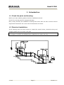
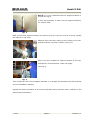
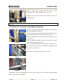
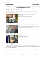
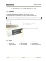
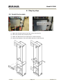
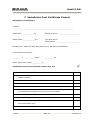
INSTALLATION MANUAL FOR HANDI-LIFT EA6 Handi-lift EA6 Table of contents 1 Introduction 3 1.1 Check the parts and drawing: 3 1.2 Electrical installation: 3 2 Forces on the building 4 3 Install the rails 5 4 5 6 7 3.1 Column installation: 5 3.2 Straight rail sections and support brackets installation: 5 3.3 Curved rail installation: 8 3.4 Fasten all “tee bolts” and support brackets: 9 Installing the lift unit 10 4.1 Place the lift unit on the rail: 10 4.2 Connect the electrical: 11 4.3 Program the PLC: 11 Installation manual for fold down seat 12 5.1 Check list: 12 5.2 Parts: 12 5.3 Tools: 12 Step by step 13 6.1 Install the bracket: 13 6.2 Make holes in the front cover: 14 6.3 Install the fold down seat: 14 Installation Test Certificate Cama 6 15 2011 Page 2 Version 1.0 Handi-lift EA6 1 Introduction 1.1 Check the parts and drawing: Before you start installing please read this installation manual. Check the received parts for transport damage. Next, study carefully the installation drawing that comes with the lift to ensure that all angels and dimensions are correct and all dimensions are there. 1.2 Electrical installation: If the drawing does not show where to install the control boxes, electrical wiring and charger. Please sort out where it all goes. NOTE! If the charger is being installed outside, please check that the electrical box for the charger is an IP65. The standard box is IP40 and for indoor use only. 6x0,6° CONTROL BOX 6x0,6° CP 2x0,75° CONTROL BOX CP 1 2x0,75° 2 OUTPUT: N L INPUT: CHARGER 3x1° OUTPUT: 24V DC 1,5A 2011 Page 3 INPUT: 100-240V AC 50-60Hz 36Watt Version 1.0 Handi-lift EA6 2 Forces on the building Wall mounted rail 1. The wall mounted bracket must be fixed by 2 pieces of M10 Glue bolts with disc and cap nuts in the top and lower holes and 1 piece of coach screw in the middle hole. 2011 Page 4 Version 1.0 Handi-lift EA6 Stanchion mounted rail 1. Support stanchions must be fixed to concrete landing and treads, They must be fixed by 3 pieces of M10 Glue bolt with discs and self-locking nuts. 3 Install the rails 3.1 Column installation: Only if the Handi-Lift is installed on columns you have to start with them. Place the columns after the measurements on the drawing they are usually numbered with the lowest number at the foot of the stairs. If not you need a drawing of the columns and measure all of them, to find out where they go. When installing the columns make sure that the columns are plumb, especially sideways. 3.2 Straight rail sections and support brackets installation: The rail system contains two identical rails, one for the lower rail and one for the upper rail. All rail sections are marked accordingly and in a sequence of the lowest number at the foot of the stairs and the highest at the top. The lower rail section are numbered and marked with the letter “B” and the upper rail section are numbered and marked with the letter “A” in each end (see fig 1). fig. 1 The specific installation drawing will indicate where the location of each rail section should be. When the rail is sorted out, it is time to mount the support brackets for the rails. At this point you only fix the brackets you do not want to tighten anything at this stage. Concentrate on one staircase at the time and the long parts of the rail first. 2011 Page 5 Version 1.0 Handi-lift EA6 NOTE! It is very important that the support bracket is plumb (see fig 2). It may be necessary to pack out the support brackets on uneven walls. fig. 2 Mark out the first support bracket you want to put up (it can be anyone of them, usually the bottom or top first). Measure from the stair nosing to the centre-line of the support bracket “tee bolt” location (see fig 3). fig. 3 When you have installed a support bracket at the top and bottom of the staircase, check the angle. (See fig 4). fig. 4 Then install the rest of the support brackets in a straight line between the two brackets see the installation drawing. Repeat the same procedure on the entire staircase taking extreme care to adhere to the dimensional information. 2011 Page 6 Version 1.0 Handi-lift EA6 Before introducing the rail to the support brackets lubricate the “tee bolt” location sleeve lightly with a freeing solution to aid installation (see fig 5). fig. 5 Place the required “tee bolts” in the rail section and introduce to the support brackets. NOTE! There can be different lengths on the fittings. fig. 6 If there are any charging points on the upper part on the rail, be certain that all the flexible hose for the wire is inserted. fig. 7 fig. 8 Slightly tighten the “tee bolts” to retain the rail. Repeat the same procedure for all upper and lower straight rail sections. At this point the support brackets should only be fixed and the straight rail sections should only be tightened with your fingers. 2011 Page 7 Version 1.0 Handi-lift EA6 3.3 Curved rail installation: The curved sections of the rail can now be fixed. Insert the rail-joining stud into the curved rail section, threading in until tight and ensuring that the grub screws are accessible from the inner side of the straight rail (see fig 9). fig. 9 Insert the joining stud into the straight section of the rail (see fig 10) and tighten a single grub screw to retain its position. fig. 10 Repeat this procedure for all curved rail sections ensuring that all joint faces are flush, smooth and fully matched together. Finally check all dimensions. Drill, tighten and fix all support brackets. Finally check all fixing for tightness. Drill holes and clean carefully. Install glue bolts M10 and tighten them lightly. When the glue is dry tighten all support brackets. On completion of the installation of all rail sections place 10mm studs into the pitch on both upper and lower rails at intervals along the rail (see fig 11). fig. 11 2011 Page 8 Version 1.0 Handi-lift EA6 With a spirit level ensure that the rack is level throughout the entire installation (see fig 12). Tighten all “tee bolts” and grub screws at the rail jointing studs. fig. 12 NOTE! If the fittings are not in plumb, it can deteriorate the operation of the lift with at least 30% 3.4 Fasten all “tee bolts” and support brackets: The rail is placed approximately 120mm from the wall, see the installation drawing. Using a spirit level ensure that the face of both rails are true and level and all measurements are correct. Rail B is installed 3mm further from the wall than rail A (see fig 13). It is not possible to keep the 3mm in turns, but only at fig. 13 the straight lengths of the rail. Drill the support brackets through the “tee bolts” (see fig 14) start with the upper rail and fix in position with seloc pins (see fig 15). Take care not to exert pressures on the rail. fig. 14 fig. 15 Thoroughly clean the installation and rail with solvent (non-oil) based cleaning agent prior to the lift unit installation. 2011 Page 9 Version 1.0 Handi-lift EA6 4 Installing the lift unit 4.1 Place the lift unit on the rail: Hand wind platform in it’s down position and remove the front cover from the lift unit. Install the loose carrying arms Plug the remote control into the control board (see fig 16) And turn on the unit at the key switch. Check the direction of travelling. fig. 16 Raise the lift unit on to enable the drive trunnions to meet the rail sections. Align trunnions and drive the lift unit carefully onto the rails (see fig 17). fig. 17 NOTE! To drive the lift you need to press and hold the re-set button (see fig 18). fig. 18 Drive the lift to the lowest part of the rail and commence the programming operation. Dismount the carrying arms and install the barrier arms to the unit and lightly lubricate the drive chain mechanism. You can now install the rail endings at the bottom and the safety-stop at the top of the rail. 2011 Page 10 Version 1.0 Handi-lift EA6 4.2 Connect the electrical: Wire all required charging points to the upper rail section ensuring that all cables are free from any damage. Charging points are placed at all the lift’s stops and wires are connected. Wire back to charging unit and electrical test operation. Install all control boxes. 4.3 Program the PLC: Remove the cover from the electrical box and connect the CimrexTM5 programming unit To program the lift see the Programming manual for Handi-Lift EA6. When the programming is done dismount the CimrexTM5 programming unit and put back the cover for the electrical box. Mount the front cover on the lift and carry out full test and commission of unit to certificate. Carry out full operational instruction to customer and hand over certificate and operation manual for Handi-Lift EA6. The customer shall approve the installation and the demonstration in writing. 2011 Page 11 Version 1.0 Handi-lift EA6 5 Installation manual for fold down seat 5.1 Check list: Before installing the fold down seat please read these instructions The fold down seat shall be mounted on the right hand side on the lift. Check that you have all the right parts, and tools to install the fold down seat. NOTE! The Lift frame does not have pre drilled holes for the mounting bracket order number # 6-2000-41 (See drawing for drilling the holes on the next page). 5.2 Parts: Mounting bracket # 6-2000-41 incl. 2 ø4x25 screws Complete fold down seat # 0-2000-00 5.3 Tools: • Drill • Ø3.8 drill bit • Ø6.8 drill bit • Ø12 drill bit • M8 threading tool • 2 13mm spanner • 4mm unbrako key • PH 3 Screwdriver • 2 M8 bolts (see page 5) • Rubber hammer 2011 Page 12 Version 1.0 Handi-lift EA6 6 Step by step 6.1 Install the bracket: Before After 1) Open the lift and remove the front cover from the lift. 2) Drill 2 ø3,8 holes and one ø6,8 hole 3) Make the M8 thread (see drawing for measurements). 4) Mount the bracket on the lift frame with the 2 4x25 screws. 2011 Page 13 Version 1.0 Handi-lift EA6 6.2 Make holes in the front cover: 5) Mark the 2 holes in the front cover. 2 M8 bolts specially made for this job. (Not incl.) 2 M8 standard bolts can be used for this job. (Not incl.) To mark the 2 holes for mounting the fold down seat in the front cover, we suggest that you screw 2 M8 bolts in the bracket and place the front cover on the lift. To make the marks in the front cover you tap on the front cover with a rubber hammer or your palm (be careful not to damage the cover when making the marks). 6) Remove the front cover again and drill 2 ø12 holes, where the marks appeared on the front cover 6.3 Install the fold down seat: 7) Install the front cover and the fold down seat. 8) Please check that there is a warning sign on the fold down seat, if not contact CAMA Lift in Denmark. 9) If it is possible please instruct the owner/ user how to operate the fold down seat. We reserve the right to make alterations on the lift. 2011 Page 14 Version 1.0 Handi-lift EA6 7 Installation Test Certificate Cama 6 Description of installation Location: ________________________________________________________________ Rated load: ____________ kg Stairlift serial no: ______________________ Rated speed: ___________ m/s Type and year of manufacturer: _________________________ Manufacturer: CAMA Lift ApS, Ellehammervej 6, DK 9900 Frederikshavn Contract electrical supply: _________ V _________ Phase _________ Hz Mains supply fuse rating: _________ A Verification test on each machine before first use a. All control devices function correctly b. All barriers, ramps, locks, hinged platforms and similar devices √ operate correctly c. Stopping distance of the stairlift is within specified limits d. All electrical safety devices function correctly e. The suspension elements and their attachments are in order f. The correct clearance dimensions and from the surrounding structure are maintained throughout the full travel of the stairlift g. The stairlift shall be subjected to insulation tests h. Verify that the polarity of the mains supply connection is correct i. Test to verify the functional operation of the overspeed detection device and safety gear j. Verify that the mechanism for emergency/manual operates correctly 2011 Page 15 Version 1.0 Handi-lift EA6 k. The alarm device when activated operates correctly l. All notices, etc. are correctly displayed m. Undergo without failure a dynamic test to check the forces imposed by the maximum working load n. Undergo the testing of the overload detection device for wheelchair platforms only Declaration A I/We certify that on ____/____/____ this stairlift was installed to the latest installation instructions and thoroughly examined and found to be free from obvious defects and to comply with the requirements of EN 81-40 and that the foregoing is a correct report of the examination. Signed: ______________________________Qualifications: Authorised Installer Address: ____________________________________ Date: ______________ Certificate of acceptance by purchaser/user I/We being the purchaser/user of the stairlift (serial no. _______________) have received and fully understood, verbal and written instructions, in association with a demonstration, from __________________________________ on its correct and safe use. Signed: ________________________________ Date: _______________ 2011 Page 16 Version 1.0