1
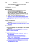
SAVER PLUS DSP SERIES
.
.
THREE PHASE IN – SINGLE PHASE OUT
15&20kVA
USER MANUAL
UNINTERRUPTIBLE POWER SUPPLY UPS
288713580
.
Important Notices
Thank you for choosing Inform UPS Systems. This document provides all the instructions necessary for
the installation and the operation of the Saver Plus DSP Uninterruptible Power Supply.
For the staff and the equipment safety, it is necessary for the users to fully read and understand this
manual before working on this equipment.
Please read the manual carefully, before working on this equipment!
Please keep the manual!
Description of the Symbols
IMPORTANT NOTICE! Please follow the instructions.
LIFE RISK! Please follow the instructions.
DANGER! Please follow the instructions otherwise the unit can be damaged or user can be hurt.
I
Contents
1
Safety .......................................................................................................................................................... 1
2
System Description....................................................................................................................................2
3
Installation .................................................................................................................................................5
3.1
3.2
3.3
3.4
4
Handling ........................................................................................................................................................................ 5
Storage ........................................................................................................................................................................... 5
Positioning..................................................................................................................................................................... 6
Connections .................................................................................................................................................................. 6
3.4.1 Ground ( Earth ) Connection............................................................................................................................. 7
3.4.2 Input Connection ................................................................................................................................................. 7
3.4.3 By-pass Input Connection .................................................................................................................................. 8
3.4.4 Battery Connection .............................................................................................................................................. 8
3.4.5 Output Connection............................................................................................................................................ 10
3.4.6 Communication Interface Connection............................................................................................................ 10
Switch on and Switch off ..........................................................................................................................11
4.1
4.2
5
Switch on..................................................................................................................................................................... 11
Switch off .................................................................................................................................................................... 11
Operating Instructions ............................................................................................................................ 12
5.1
Unit Operation ........................................................................................................................................................... 12
5.1.1 Operating Modes................................................................................................................................................ 12
5.1.1.1
5.1.1.2
5.1.1.3
5.1.1.4
5.1.1.5
5.1.1.6
5.1.1.7
5.1.2
Operating Types ................................................................................................................................................. 14
5.1.2.1
5.1.2.2
5.1.2.3
5.1.3
Online Mode and Voltage Tolerance..................................................................................................................17
By-pass Mode Voltage Tolerance........................................................................................................................17
Battery Management and Autonomy Time........................................................................................................17
Temperature Management....................................................................................................................................19
Communication Interface.....................................................................................................................................19
Abnormal Conditions Operating Principles................................................................................................... 21
5.1.4.1
5.1.4.2
5.1.4.3
5.2
Online Priority Operating (Normal Operation) ................................................................................................14
By-pass Priority Operating (Green Mode) .........................................................................................................15
UPS out of Function Operation ..........................................................................................................................16
Operating Features and Values ........................................................................................................................ 17
5.1.3.1
5.1.3.2
5.1.3.3
5.1.3.4
5.1.3.5
5.1.4
On-line Mode (ONLINE)....................................................................................................................................12
By-pass Mode (BYPASS)......................................................................................................................................12
Battery Mode (BATTR) ........................................................................................................................................13
Shutdown (SHUTD) .............................................................................................................................................13
Inverter Failure (INVFLR)...................................................................................................................................14
Output Failure (OUTFLR)...................................................................................................................................14
Wait Mains (WTMNS) ..........................................................................................................................................14
Overload..................................................................................................................................................................21
Output Short Circuit .............................................................................................................................................21
High Inrush Current Load at the Output...........................................................................................................22
Display ......................................................................................................................................................................... 22
5.2.1 Front Panel.......................................................................................................................................................... 22
5.2.1.1
5.2.1.2
5.2.1.3
5.2.2
Display (LCD) ........................................................................................................................................................23
LEDs........................................................................................................................................................................24
Buttons ....................................................................................................................................................................25
Alarms.................................................................................................................................................................. 25
6
Important Operating Notices.................................................................................................................. 26
7
Maintenance ............................................................................................................................................ 28
8
Trouble Shooting ..................................................................................................................................... 29
9
Technical Specifications (15kVA Saver Plus DSP UPS)......................................................................... 31
10
Technical Specifications ( 20kVA Saver Plus DSP UPS )....................................................................... 33
II
1
Safety
For the staff and equipment safety, it is necessary for the users to fully read and
understand this manual before working on this equipment.
Avoid the sudden temperature changes, which can cause condensation inside the UPS. Otherwise,
wait for at least two hours before switching on.
UPS has to operate in an environment suggested in this manual. Please read chapter 3.3 ‘Positioning’.
Do not close ventilation holes or other openings.
Do not let enter any foreign materials inside the UPS.
Installation and commissioning have to be done by authorized technical service.
Earth (ground) connection has to be done.
Do not plug in and remove the communication interface cables during the lightning weather
conditions.
Avoid the risk of fire, all the connections have to be done by suggested cable dimensions. All cables
have to be isolated and properly installed.
Do not connect overload to the UPS output.
Do not open the UPS doors. There is high voltage risk.
Maintenance has to be done by authorized technical service.
In case of emergency (damage of the cabinet, front panel, or connections etc.) switch off the UPS, cut
off input voltage, and inform authorized technical service.
Please make the necessary packing if it is obligatory to move the UPS.
1
2
System Description
On-line UPS connected between mains and load protects the load against voltage fluctuations, ripples, and
electricity cuts off.
Our UPS during the on-line operation provides stable pure sine wave. This pure sine wave is not affected
from the input voltage fluctuations. This helps to extend the life time of your sensible loads. Power factor
of the current consumed from the mains is nearly one. You do not have any problem on generator or
isolation transformer applications. Your reactive energy consumption decreases.
Over 80V mains voltage, smart battery charger charges the batteries. Batteries do not need any
maintenance.
In case of longer overload or inverter failure situation, UPS transfers the load to by-pass line, and load is
supplied from the by-pass input. When the normal conditions come back, UPS shall continue to supply
the load through inverter.
UPS control and management is done by digital signal processor ( DSP ) which is 200 times faster than
standard microprocessors. This helps to make your UPS smarter. DSP uses all the sources on optimum
conditions, observes the failure conditions, and communicates with your computer system.
UPS has standard communication interface. Using Inform software, you may protect your data and
operating Systems.
UPS block diagram is shown below.
2
Inverter Thyristors
Input and Output EMI filters
These
filters
prevent
electromagnetic
interference between UPS, mains and loads.
Your UPS and loads are protected against high
voltage.
Input Thyristors
This helps to cut the energy flow between the
UPS input and boost rectifiers during the battery
mode or battery test.
Boost Rectifier
This helps to separate inverter from the output
electronically in case of by pass mode operation
or UPS output off conditions.
By-pass Thyristors
This helps to separate by-pass input from the
UPS output electronically.
Battery Thyristors
This helps to separate battery from the boost
rectifier electronically.
On mains operation, the boost rectifier adjusts
the mains voltage to the necessary DC voltage
level required for the inverter and helps to
provide sinus current with a power factor near
to 1 from the mains.
Battery
On battery mode it increases the battery voltage
level, required for the inverter and uses current
from the battery with a low ripple ratio thus
extending the battery life.
By-pass Switch
Inverter
The inverter helps to obtain a very constant AC
voltage level at the output by using DC voltage
at the boost rectifier’s output.
The necassary energy supply is obtained from
the batteries whenever the input mains supply is
not sufficient for the supply of the loads.
It is a mechanical switch which connects the ups
output to the bypass input and provides
uninterruptible transfer. It is generally used to
isolate the ups without disconnecting the load
from output and the mains from input.
By-pass Input
In some cases, it is requested to supply by pass
line from another mains or sources. In this
application, it is used split by-pass. (Please
inform your contact about your need)
Your UPS features:
Feature
IGBT Technology
Transformerless design
Benefit
Compact design, small dimensions and low weight
DSP is 200 times faster than standard microprocessors. This provides;
DSP (digital signal processor)
technology
To use all the sources in optimum level
To observe carefully the failure conditions
High input power factor. This helps;
PFC technology
To consume low reactive power
Not to load the installation extra (cables, transformers, generators)
Clean power for the mains
Wide input voltage tolerance
(on-line operation even the mains is
between 80 – 280 V)
This helps to reduce battery usage and guarantee battery to be fully
charged and extend the battery life time.
On-line double conversion
technology
UPS output voltage is sine wave same as ideal mains source. UPS output
total harmonic distortion is very low.
3
Feature
On-line and battery modes
operation against inrush current
On-line and battery modes
operations in short circuit
conditions
Benefit
Some loads when they are switched on, consumes high inrush current.
On such cases normal UPS switches off, or passes to by pass.
Our UPS behaves like a current source. (In case of high inrush current
consumption, UPS adjust the output voltage and fix the current value.)
Load is not affected the from inrush current.
In case of a short circuit at output, UPS behaves like current source, (In
case of high current consumption, UPS adjust the output voltage and fix
the current value), and trigger the fuse between UPS and load. So short
circuit condition is over, and other loads are not affected.
Normal UPSs switch off in such cases.
Thanks to algorithms used in battery charging, battery lifetime is
extended. This helps:
To continue charging the battery even the mains input go down to
80V.
Load independent charging voltage.
Info (smart) Battery Management
Temperature controlled battery charging
Additionally;
Battery autonomy time is calculated, thanks to artificial intelligent
algorithms.
Current ripple is minimum level during the discharge.
Battery testing is available.
UPS measures the temperature of different internal parts, and
calculates semi-conductor junctions’ temperature. This helps;
Temperature Management
To calculate overloading time in a reliable way.
To protect against over temperature.
UPS continues its online operation for a certain period during overload
condition. This depends on overload percentage, and temperature of
semi conductors. Calculation is done as follows;
Overload Time Management
Load is supplied for a certain period by UPS, considering output
fuse temperature characteristics, and if by-pass input voltage is
available, and then pass to by-pass.
Meanwhile, if junction temperature passes the critical level, if bypass input voltage is available, then passes to by pass.
Non-moving parts except the fans
Maintenance free lead acid battery
usage
Communication interface
Less maintenance need
Using Inform software, you can protect your data and operating
Systems.
Output voltage is not affected by changes on the mains input and load level.
High efficiency (Low power consumption)
Uninterruptible Manual Bypass Feature
4
3
Installation
Check if the UPS has been subjected to any damage before unpacking it.
If you notice any damage, please contact to transport firm. Check if all the additional parts have
been supplied with the UPS.
Please make sure that the packing contains the following;
UPS
User Manual
Test Reports
Before the installation, please check if your UPS is customized following your special
requirements (if any).
In standard UPS, output voltage and frequency are adjusted to 220 V/50 Hz.
3.1
Handling
UPS and battery weights are given in the chapter 9. You may calculate the total weight.
If needed to move the UPS, it is obligatory to pack the unit. It is suggested to keep the original
packing.
3.2
Storage
Please store the UPS and batteries in an environment where the temperature is between –15 °C +55 °C,
no receipt of direct sunlight, far from the heating, in a dry place.
Environmental humidity must be between 20% 95% (none condensing).
If the batteries will be stored more than 3 months, it is suggested to charge the batteries periodically.
Relation between storage temperature and period is shown below;
Storage temperature below 20 °C’, once per 9 months
Storage temperature between 20 °C and 30 °C, once per 6 months,
Storage temperature between 30 °C and 40 °C, once per 3 months,
Storage temperature above 40 °C’, once per 2 months
Please follow up the instructions of “installation” chapter for earth, input, and battery connections. Please
turn to ‘ I ’ position UPS’s battery and input fuses and also additional battery cabinet fuses if present.
Please charge the batteries at least 12 hours.
5
3.3
Positioning
UPS and battery cabinet (if any) have to be positioned in an environment;
•
No direct sun access,
•
Dry,
•
Far from the heating equipments
•
Well-ventilated.
•
No excessive dust
In order to maintain adequate ventilation of UPSs and battery cabinet, ensure the air vents are not blocked
and leave at least 20cm space at the rear side of the unit for ventilation.
Even though the operating temperature of the UPS and batteries are between 0-40 °C, It is suggested to
provide an environment temperature between 20-25 °C to get maximum performance from the UPS and
batteries.
Environmental humidity must be between 20% 80% (none condensing).
3.4
Connections
Connections must be done by authorized technical service staff. Life risk for user!
Temperature changes such as from cold to hot environment may cause condensation. It is
dangerous to operate the UPS. Please wait at least two hours before making the connections.
Connection terminals are in the front side of the UPS.
Standard UPS fuses and connectors settlements are shown below;
6
Units with internal batteries have hazardous voltages on the battery connectors even if the battery
circuit breaker is in “0” position. Do not touch the battery connectors.
Units with internal batteries can produce output voltage even if no connection is made.
Therefore, it is mandatory to keep all circuit breakers in “0” position and not to push the buttons
on the front panel during installation.
Please follow the instructions as explained below.
3.4.1
Ground ( Earth ) Connection
UPS ground (earth) connections have to be done.
UPS input ground (earth) connector has to be connected to (low resistive) ground (earth) line.
Load ground (earth) connections have to be done through UPS output ground connector.
If any battery cabinet exists, grounding has to be done through battery ground (earth) connector.
Minimum cable crossections are given in the chapter 9.
3.4.2
Input Connection
Please add 4 poles miniature circuit breaker to distribution box where to UPS is to be connected. Please
do not forget to add leakage current relay.
It is suggested to add to a miniature circuit breaker that fits UPS input fuse value. The value&type of the
fuses are stated in the technical specifications section.
Leakage protection relay value must be the total value of 30mA (UPS input leakage current relay) and total
leakage current value of the load connected to UPS. Relay must be protected type against peak current
that can be happened on EMI filter capacitor.
Above informations are given for the supply of UPS only. If more equipment will be supplied, please
make the calculation accordingly.
Changes on distribution panel have to be done by authorized persons only.
After the necessary changes, switch on ‘ 0 ‘ position the automatic fuse on the distribution box, and
connect the phases to R, S, T clemenses through the automatic fuse on the panel, and neutral to N
connection.
Before connecting the input cables, switch on ‘ 0 ‘ position the automatic fuse on the distribution
box.
Cables to be used for UPS and distribution box connections are shown in the chapter 9. Risk of
fire!
IEC 62040-3 (EN 50091-3) standard, suggests to put below sticker next to automat that UPS to
be connected in the distribution box against the risk of leakage reverse voltage. Otherwise can
cause life risk!
7
Isolate uninterruptible power supply before working on this circuit.
3.4.3
By-pass Input Connection
Please follow up the below instructions for the by-pass line connection;
Please add two poles automatic fuse to distribution box where to UPS is to be connected. Please do not
forget to add leakage current relay.
Fuse value&type is stated in the technical specifications section of the user manual.
Leakage protection relay value must be the total value of 30mA (UPS input leakage current relay) and total
leakage current value of the load connected to UPS. Relay must be protected type against peak current
that can be happened on EMI filter capacitor.
Above informations are given for the supply of UPS only. If more equipment will be supplied, please
make the calculations accordingly.
Changes on distribution box have to be done by authorized persons only.
After the necessary changes, switch on ‘ 0 ‘ position the automatic fuse on the distribution box, and
connect the phase to by-pass phase Clemens (BYP) through the automatic fuse, and neutral to N1
clemens.
Before making by-pass connection, switch on ‘ 0 ‘ position the automatic fuse on the distribution
box.
3.4.4
Battery Connection
If the batteries are installed inside the UPS cabinet, there is no need to make battery connections.
If the batteries shall be put in a separate additional battery cabinet or make parallel to the batteries inside
the UPS, please follow up the instructions below;
Switch on to “0” position the battery cabinet fuse.
Connect the B- on the battery cabinet to B- on the UPS
Connect the B+ on the battery cabinet to B+ on the UPS,
Connect the N3 on the battery cabinet to N3 on the UPS,
Connect the PE on the battery cabinet to battery ground (earth) on the UPS.
Locate the battery fuses to their location sockets.
In order to obtain better performance from the battery, please charge at least 10 hours before the
operation.
8
You may do the initial charge of the batteries after the connection of the loads. But during the initial
charge, if the UPS transfers the loads to the output, then the charge wouldn’t be completed. In order to
prevent this, the loads shouldn’t be supplied through UPS all along the initial charge time. Please follow
up the below procedure;
In order to make the initial charge after connecting the loads to the output;
•
Perform the output connections as in the explained section,
•
Turn the by-pass switch in to “I” (by-pass) position on the UPS,
•
Turn the UPS battery fuse and external battery cabinet fuse( if present ) in “I” position,
•
Turn the automatic fuses on the distributions panel that the UPS is connected to mains and
by-pass in “I” position,
•
Turn the input, by-pass and battery charger fuses of the UPS in “I” position,
•
Turn the output fuse of the UPS in “I” position,
•
Turn the fuses between the UPS and the loads in “I” position.
The loads are started to be supplied through manual bypass switch. 10 seconds after the UPS is energized,
you start to observe “BYPASS OK G” or “SHUTD. OK” on the top line of the front panel. On the
bottom line “MB” message is still continued to be observed.
The loads cannot be protected from the outgates and disturbances during the initial charge
period due to they have been transferred to by-pass input.
If the mains cut off during the initial charge, the charge time should be prolonged as much as
the cut off time.
At the end of the advised charge time, before switching on the UPS, the following items should be
performed;
•
Switch off the loads,
•
Turn the input and by-pass fuses of the UPS in “0” position,
•
Turn the battery fuse of the UPS and external battery cabinet fuse (if present) in “0” position,
•
Turn the manual by-pass switch in “0” position.
Now you can switch on the UPS safely.
In order to make the initial charge before connecting the loads to the output;
•
Turn the external battery cabinet fuse (if present) in “I” position,
•
Turn the battery fuse on the UPS in “I” position,
•
Turn the automatic fuse on the mains distribution panel, where the UPS is connected, in “I”
position,
•
Turn the UPS input and battery charger fuse in “I” position.
If the mains cut off during the initial charge, the charge time should be prolonged as much as the
cut off time.
9
Do not touch any clemens on the unit during the operation. For your own safety, please make the
output connections after the end of charging process according to the explanations in the related
section.
At the end of the advised charge time, before making the output connections, the following items should
be performed;
•
Turn the UPS input fuse in “0” position,
•
Turn the battery fuse and external battery cabinet fuse (if present) in “0” position,
•
Turn the automatic fuse on the mains distribution panel, where the UPS is connected, in “0”
position.
•
Please check and control that the manual bypass switch is in “0” position.
Now you can make the output connections safely.
3.4.5
Output Connection
It is suggested to use different fuse and leakage current relay for each independent load. In case of
short circuit, related fuse will be triggered and remaining loads shall continue to be supplied.
Nominal current value of the fuse between load and UPS must be lower than the fault clearing
current value given in the ‘ Technical Specifications ‘ chapter. Otherwise, fuse shall not be
triggered before 10ms, and load energy shall be interrupted.
Before making output connections, switch on to ‘ 0 ‘ position the automatic fuse on the
distribution box, UPS input, output, battery, and by pass (if any), additional battery cabinet( if
any) automats.
Load will be connected L2, N2, and ground (earth) connections at the rear side of the UPS.
Cables dimensions between UPS and loads have to be chosen following load current.
Load power connected at the UPS output, must be not bigger then UPS nominal power.
3.4.6
Communication Interface Connection
Please contact to authorized Inform distributor to get the optional accessories such as SNMP adapter,
modem, remote control panel, software, ..etc. Information about this section is given in the
“communication interface” section.
10
4 Switch on and Switch off
4.1
Switch on
After making all the connections mentioned in the chapter 3, you need to switch on to ‘ I ‘ position the
automatic fuse on the distribution box, UPS input, output, battery, and by pass automats (If there is any
external battery cabinet, then turn its fuse in “I". If mains voltage is within the limits, the unit switches on.
UPS makes self-test for few seconds to check if everything is normal, and then starts to supply the load.
If you want to switch on the UPS when the mains is out of the limits, please press ‘ CS ‘ button.
4.2
Switch off
To switch off the UPS, please press “0” button. Then the load is transferred to by pass. If the mains is out
of the limits, UPS pass to shut down mode.
To stop the load to be supplied, please turn the UPS output fuse to “0” position.
To switch off the UPS, please turn all the fuses to “0” position.
Even though all the fuses are in “0” position, there is still energy on the connections. Do not
touch.
If any work will be done on UPS clemenses, fuses on mains, by pass distribution box, battery
cabinet (if any), must be turned to “0” position.
Devices with internal batteries have hazardous voltages on battery connectors even if the
battery circuit breaker is in “0” position. Do not touch these connectors.
11
5 Operating Instructions
5.1
Unit Operation
5.1.1
Operating Modes
Following the status of mains&by-pass voltage, UPS can operate either one of the below operating modes.
5.1.1.1
On-line Mode (ONLINE)
Online mode is available if the mains is within the allowed operating limits. In this mode, UPS supply the
load and charge the batteries. Load is supplied through inverter and inverter is on-line.
If;
On-line mode is chosen, the mains input is in the acceptable limits, and there are no abnormal
conditions ( such as over temperature, overload, failure ..etc),
Green mode is chosen, by pass input voltage is out of limits, but the mains input voltage is in the
acceptable limits, and there are no abnormal conditions (such as over temperature, overload, failure
..etc),
UPS operates in on-line mode.
5.1.1.2
By-pass Mode (BYPASS)
If the voltage in the by-pass input is transferred to the output by using either electronic or manual switch,
this mode is called by-pass mode. Your UPS has both electronic (static) and manual switch.
You can pass to Maintenance Bypass Mode by using the manual bypass switch on the ups. This switch is
used to transfer the bypass voltage to the output of the ups manually when the ups is not in function.
Maintenance Bypass Switch (manuel bypass) is an uninterruptible switch. In case of use, the
instructions in section 5.1.2.3 should be followed up properly in order to maintain an
uninterruptible transfer to byapss. In condition to transfer from manual bypass line to normal
operations, the instructions in 5.1.2.3 should be followed up.
On by-pass mode, by pass input voltage is transferred to output through the thyristors. Load is supplied
by by-pass input voltage. Inverter is off.
By-pass input voltage must be within the operating limits.
The unit;
•
Stays at this mode when green mode is chosen, if by pass input voltage is within the
acceptable limits,
•
On-line mode is chosen, by-pass input voltage is within the acceptable limits, if one of the
below conditions occur, UPS passes to by-pass mode. If normal conditions are obtained, then
UPS passes to on-line mode;
*Prolonged overloading,
*Over temperature,
*Failure on the UPS,
During the on-line operation, if the by-pass input voltage is within acceptable limits, or in green mode
operation, when you push to“0” button, UPS passes to by-pass mode. If the by-pass input voltage is
out of limits, UPS does not pass to battery mode, and switch off itself.
12
If the UPS is transferred to by pass mode by pushing “0” button, in case by-pass input voltage is
out of the limits, UPS passes to shutdown mode or switch off, depending on mains voltage. It is
suggested to use green mode if you don’t want any interruption.
If the by-pass input voltage gets out of limits after the “0” button is pressed during on-line operation, UPS
shall switch into Shutdown Mode.
If UPS passes to by-pass mode because of overload conditions, and by-pass input voltage gets out of the
limits, it is dependent on the amount of load for the ups to return to online operation.
5.1.1.3
Battery Mode (BATTR)
In this mode of operation, UPS converts the battery voltage to a suitable DC voltage, which can be
converted to a voltage value equal to mains voltage of the inverter. UPS is at the same time on by-pass
mode. This is an exceptional case that UPS is on two modes at the same time.
During on-line mode, and mains input is out of the limits, UPS passes to battery mode. (If there are
no other abnormal conditions). Necessary energy to operate the inverter is supplied by the battery.
During green mode, both mains input and by-pass input are out of the limits, UPS passes to battery
mode. Necessary energy to operate the inverter is supplied by the batteries.
During green mode, mains input only is out of the limits, inverter is supplied from battery, but load is
supplied from the by-pass line.
You may switch on the UPS by pushing “CS” button, even if mains input is lower than 130 V or input
fuse is on “0” position. In this case UPS switch on shutdown mode, and make self test. If everything is ok,
UPS operate on battery mode.
Autonomy time depends on battery type, quantity, and load level. UPS stops feeding the loads if the
battery voltage falls under a certain value. Battery life decreases if battery capacity falls below a certain
level. Therefore, UPS stops operating in battery mode when the battery capacity falls below 30% of its
total capacity.
5.1.1.4
Shutdown (SHUTD)
During the shutdown mode, even the UPS is switched on, there is no energy on the output and load is not
supplied.
UPS makes self-test during the start up to check if everything is normal. During this operation, UPS is on
shutdown mode.
Other shutdown mode conditions;
User push the “0” button when the by-pass input is out of the limits,
UPS switches into shutdown mode if by-pass input voltage gets beyond limits, while mains voltage is
within limits and UPS is disabled,
User push the “0” button, and send shut down command through communication interface.
In addition,
During the battery mode, if shut down command is sent through the communication interface, and if
the mains comes back to normal conditions, for a short period UPS passes to shutdown mode, and
then passes to normal ( mode chosen by the user, on line, green or by pass mode) operating mode.
During the on-line or green mode operation, if shut down command is sent through communication
interface, for a short period, UPS passes to shutdown mode, and then passes to normal ( mode
chosen by the user, on line, green or by pass mode) operating mode.
13
If “0” button is pushed during the start up self-test, even the test is successful, UPS stays at this mode.
In order to pass on-line mode, you need to push “I” button once.
5.1.1.5
Inverter Failure (INVFLR)
If there is a failure, UPS pass to INVFLR mode. If failure happens during the on-line operation, UPS
passes to by-pass mode. If by-pass input is not available, it gives OUTFLR.
When you see the UPS in INVFLR operation, take out the load, and try to start up the unit
maximum two times. If it does not work, please contact to technical service.
5.1.1.6
Output Failure (OUTFLR)
If there is any possibility to damage the loads, UPS passes to OUTFLR mode. UPS shuts down the
output, and loads are not supplied.
During the OUTFLR operation, UPS is not switched off; there is no output voltage only.
Possible reasons are listed below;
During the on-line operation, short circuit happens at the output and continues more than 100 ms,
Due to conditions, UPS try to pass to b-pass mode, but the by-pass input voltage is not within the
acceptable limits,
During the INVFLR operation, UPS try to pass to by pass mode, but does not succeed.
When the UPS is on OUTFLR operation, “0” sign appears on the right side of the display.
If OUTFLR conditions are finished, if you push twice to “I” button, UPS starts to its normal operation.
Before to start the normal operation, please check the fans on the rear side. If the fans are not
working, please contact to technical service.
Do not open the case or put any object in the holes to check if the fans are working.
5.1.1.7
Wait Mains (WTMNS)
Wait mains, means that UPS cuts off the output voltage until the mains input comes to allowed limits.
When the mains input reaches to acceptable limits, UPS passes to on-line mode.
In order to start WTMNS operation, you need to send the shutdown command through communication
interface during the battery mode. At the end of time given by the user, UPS pass to WTMNS operation.
If shutdown command is sent during the on-line or green mode, at the end of defined time, UPS passes to
shutdown mode and then returns to the operation mode defined by the selected operating type.
During the WTMNS operation, if you want to switch on the UPS manually. Please press first to“0”
button, and switch off, and push to “CS” button. UPS starts on battery mode.
5.1.2
Operating Types
5.1.2.1
Online Priority Operating (Normal Operation)
When you turn the input fuse to “I” position, if the mains voltage is over 130V, UPS is switched on, and
after the test if everything is normal and if the “0” and “I” buttons were not pressed during the test, UPS
starts in this operation type.
14
The same is true if the UPS has been started up by pressing CS button in case of a mains interruption.
If the mains input is out of the tolerance, UPS passes to battery mode. When the mains input returns to
normal conditions, UPS passes automatically to on-line operation.
Even though the mains input is within the operating limits, but there are abnormal conditions (such as
over temperature, continuous overload, failure etc), UPS passes to by-pass operation if the by-pass input is
within the operating limits. If the by-pass input is out of the tolerance, the unit either passes to shutdown
mode or switch off. If the unit passes to by-pass mode, when the abnormal condition is over, UPS starts
to online operation.
You will see on the right top of the screen as ‘ N ’ sign indication during the normal operation.
Normal Operation is the safest operating type. Load is fully protected on normal operation only.
To pass to green mode operation from the normal operation, please push the “I” button;
Two times if there is audible alarm,
One time if there is no audible alarm.
To pass to UPS out of function operation, please push the “O” button.
5.1.2.2
By-pass Priority Operating (Green Mode)
UPS operates on by-pass mode if the by-pass input is within the operating limits. If the by-pass input is
out of the limits, UPS check if the mains input available for on-line operation, then pass to on-line
operation. When the by-pass input turns to its normal conditions, it passes to by-pass mode.
If the by-pass and mains input are not available or out of limits, UPS passes to battery mode. Which ever
comes to its normal conditions first, UPS passes that operation mode.
On green mode, inverter is off, and efficiency is very high. This provide energy saving.
It is suggested to use normal operation. During the green mode, load is not fully protected against
output short circuits, and disturbances.
You will see on the right top of the screen as ‘ G ’ sign indication during the green mode operation.
To pass to on-line mode operation from the green mode operation, please push the “I” button;
Two times if there is an audible alarm,
One time if there is no audible alarm.
To pass to UPS out of function operation, please push the “O” button.
15
5.1.2.3
UPS out of Function Operation
transfer from online operation to manual bypass
Please proceed as described below in order to transfer the load from online operation to manual bypass
operation without interruption. The below instructions should be followed up respectively for user safety
and preventing the load to be disenergized .
•
•
•
•
•
•
•
please check that UPS is at online operation mode ( On the front display panel of the ups, “
ONLINE OK” message should be observed. )
Pressing the “ I “ button on the front panel of the ups for necessary times, provide the transfer to
GREEN MODE . ( On the right upper line of the display panel, “G” letter should be observed. )
On the front display panel “ BYPASS OK” message should be observed and the bypass LED
should lit.
Bring the Manual Bypass Switch to “1” position.
Please check and observe the “MB” message on the lower line of the front display panel.
Bring the output, bypass, battery charger and battery fuses to “0” position .
Please check and control that the UPS is switched off completely.
Now the connected loads are supplied through the manual bypass switch of the ups from bypass line. In
case of a energy cut off during this operation mode, your connected
loads shall remain without energy.
CAUTION:
Although the fuses of the UPS is at “0” position and the UPS is switched off, if the manual bypass
switch is at “1” position than there is still bypass voltage on the output Clemens of the ups and on the
supply part of the loads. Do not operate on these points ( output Clemens and load supply parts)
before taking the manual bypass switch to “0” position.
Check the user manual in case of non-described conditions in this instruction sheet.
Exceptional Cases
If you can not transfer your UPS to static bypass by pressing “I” button before passing to manual bypass
and observe “ ONLINE OK G” message on the front panel, this is an indication of the unavailibility of
the bypass voltage for transfer. This means that the bypass voltage and/or frequency is out of allowed
limits. Please check and control that you have the bypass connection and bypass fuse is in “1” position.
until you observe “G” message on the front panel, please pres continously to “I” button. If you bring the
manual bypass switch in “1” position although you have not received the “BYPASS OK” message on the
front panel, then you energise the loads with an inconvenient voltage and/or frequency. During this
transfer even your loads may remain without energy for a while. If you observe “BATTR. OK” message
on the front panel, then this means that the ups is operating from the mains due to the lack of input
mains. If the input fuse is not in “0” position and there is bypass voltage, then by pressing “I” button
from the front panel, you can obtain the transfer to green mode operation. If you observe “BYPASS OK”
message on the front panel, then by bringing the manual bypass switch to “1” position, you can provide
the uninterruptible transfer to manual bypass line.
16
transfer from manaul bypass operation to online operation
•
•
•
•
•
•
•
5.1.3
5.1.3.1
If the UPS is switched off , then bring the battery, battery charger, output, bypass and input fuses
to “1” position RESPECTIVELY.
Please check and control that UPS is switched on.
After a period of switching the UPS on, “MB” message on the front display panel should be
observed and bypass LED should be litting.
Bring the manual bypass switch to “0” position.
Please wait for 10seconds.
On the front display panel, if there is mains then “ONLINE OK” , if there is no mains then “
BATTR. OK” messages should appear.
If you observe “ BATTR. OK” message the please recheck again if the mains is present, and if
the input fuses on the distribution panel and the input fuse on the UPS is at “1” position.
Operating Features and Values
Online Mode and Voltage Tolerance
Voltage tolerance sub-limit for on-line operation depends on the load level.
Load and voltage relation is given for the sub-limit in the chapter 9.
Voltage tolerance for upper limit does not depend on the load and is 280V. If the voltage is over 280V,
UPS passes to battery mode. To come back to on-line mode, it is necessary that the voltage should go
down to 275V.
5.1.3.2
By-pass Mode Voltage Tolerance
Factory configuration for by-pass mode voltage tolerance is between 198 V – 242 V (±10% of the
nominal input voltage). You may ask to change this limit, please contact to authorized Inform partner. If
the voltage is out of the above limits, UPS does not work on by-pass mode.
To come back on by-pass mode, by-pass voltage has to be within between 203 V- 237 V (following the
factory settings) (+5V lower limit) and (-5V upper limit).
5.1.3.3
Battery Management and Autonomy Time
UPS has smart battery management system. To be able to charge the batteries, UPS has to be on on-line
mode, and mains input within the operating limits. Thanks to algorithms used, smart battery management
increases the lifetime of the batteries. These advantages are as follows;
Charge the batteries even the mains input goes down to 80V,
Load independent battery charging current,
Temperature controlled battery charging,
Battery current and voltage are shown in the figure below;
17
Time - Charge Voltage and Current
Charge voltage, and current
boost charge
area
temperature
compensation
constant power zone
float
charge area
time
Charging voltage
Charging current
Battery current is controlled in a way to keep stable the power transferred to batteries in fixed power zone.
If the voltage passes a certain value, balance charging starts. It is applied fixed voltage14.4V per battery
(2.4V per cell). Boost charging takes 30 minutes. Then it passes to float charging. During the float
charging, it is applied fixed voltage 13.5V per battery (2.25V per cell) in 25 °C environment temperature.
UPS stays in this zone until the battery mode operation starts.
Autonomy time is an immeasurable quantity. UPS calculates and shows battery back up time, thanks to
artificial intelligent algorithms. Bridging time depends on battery capacity and quantity, load level, battery
charge level status. Autonomy time values which are calculated while the UPS is operating in battery mode
are more accurate than those calculated while UPS is operating in another mode. Please check chapter 9 to
see the back up time of a fully charged on full, and half load conditions.
In order to obtain longer autonomy time, you may add batteries either internally (if possible), or
in an external battery cabinet. Please contact to authorized service.
During the discharge (battery mode) current ripple is on minimum level.
UPS has battery testing feature. It warns the user for battery life. Battery test is done in every 90 days
automatically. If user has software, user may perform battery test whenever required. The best result is
taken when the batteries are full, and UPS is operating on nominal load.
During the battery test, UPS passes to battery mode, and it takes maximum 10 seconds. During this test, if
the battery voltage goes below a certain level, battery test fails. You may see BATTF sign on the screen,
and UPS gives audible alarm, and fault led blinks. At the end of test, UPS goes to its previous operating
mode, but the alarms continue.
If the “Line” led is always on (even the mains input is available), BATTR sign exists on the
display, and battery led is on, it means battery test is on process.
If the test is done when the batteries are empty, please let the UPS charge the batteries first. Please check
BATTF sign disappears. If not, contact to authorized service.
If battery test fails, one of the possible reasons is that batteries are at the end of their lifetime.
Please contact to authorized service.
If the performed test is successful, UPS continues to its previous operation mode.
Battery lifetime depends on the battery type, charge discharge quantity, discharge depth, and
environmental temperature. Please see below figure, battery life is the zone between the two lines.
18
Battery Lifetime [year]
Temperature - Battery lifetime
100
10
1
0,1
0,01
0,001
0
10
20
30
40
50
60
70
80
o
Temperature [ C]
To check the autonomy time for certain load level, you choose normal operating mode, please turn the
input fuse to “0” position while the UPS is loaded with the desired load level. Then UPS passes to battery
mode. You will see on the screen BUV sign, UPS will shutdown in a few minutes. The time between bypass mode and switch off of the UPS is the autonomy time. If you don’t want any interruption on the
load, please turn the input fuse to “I” position when you see the BUV message.
Please make sure that the batteries are full before the test.
5.1.3.4
Temperature Management
UPS measures the temperature of some points inside the UPS, and calculates the temperature of
semiconductor junctions by using electrical values, temperature of which is immeasurable. In this way;
Overload time is precisely calculated.
UPS is able to perform advanced over-temperature protection.
5.1.3.5
Communication Interface
Please contact to authorized distributor to be informed how to get SNMP adapter, software,
communication cable, modem …etc.
Communication interface has the following features;
Communication without operator,
Direct communication between your PC and UPS,
Add as a new Client to the Network,
Inform the operating mode to an external unit.
Above features are optional.
Do not remove or plug in communication interface during bad weather (such as lightning)
conditions.
5.1.3.5.1
Free Contact Communication
UPS 9-Pins D-SUB female socket (free contact) gives the following signals;
UPS shutdown
This feature is used for remote shutdown and switch on via PC.
(Pin 6: high (+ 5V... + 12V), Pin 7: 0V)
19
Mains failure
This signal (between Pin 2 and Pin 4 contact closed) is given if the mains input is out of the
allowed operating limits, and disappears when the mains input comes to its normal conditions.
Low battery
This signal (between Pin 5 and Pin 4 contact closed) is given if the battery capacity is less than
30%.
By-pass active
This signal (between Pin 1 and Pin 4 contact closed) is given if the load is supplied by the by-pass
input.
Summary alarm
This signal (between Pin 8 and Pin 4 contact closed) is given if battery mode, low battery, by-pass
active or “Fault” sign is blinking.
An example of free contact communication is given below. If the system in communication sends DC
signal, in order to cut the current, R resistors must be 50 k. If the current, which will be carried by the
contacts is greater than 0,1Ma, it is necessary to use the DSP UPS relay-interface board ( stock code=
105430010065) which can be purchased as an accessory.
5.1.3.5.2
Communication via serial port
RS232 serial communication port is connected to 9Pin D-SUB-male connector. Pin connections are as
follows;
GND - Pin 5 ,
TXD - Pin 3 ,
RXD - Pin 2 ,
The remaining pins do not have any connection.
20
In the below diagram, computer serial communication connection via RS232 is shown as an example;
5.1.4
Abnormal Conditions Operating Principles
5.1.4.1
Overload
Connection of loads to the output of the UPS that exceeds the nominal power of the unit is called
“ Overload “.
UPS can feed the load that exceeds the nominal power of the unit for a limited period while operating
online. This period depends on the load quantity and the initial temperature of the overload on the
semiconductors.
The Unit follows up the following procedure in the calculation of the overload time:
It feeds the load for a period which will not cause the output fuses to blow out using a thermal model
which has been formed by considering the output fuses’ thermal characteristic, than it transfers the
load to by-pass line if the bypass input voltage value is within the allowed limits.
Meanwhile if the junction temperature passes over a certain value, than it transfers the load to by-pass
line (assuming the bypass voltage is acceptable) before the calculated time, which has been found out
with the help of thermal model.
Overload time versus overload quantity diagram is shown in the “technical specifications” section of the
user manual.
If the unit is working on by-pass mode during the initial start of the overload or if it has passed to by-pass
mode because of the overload, than the only protection in the system is the automatic fuses in the circuit.
In case of the UPS fuse is switched off than all the loads on the output shall be without energy.
For safe operation, avoid the system from overloading.
.
5.1.4.2
Output Short Circuit
If a short circuit occurs at the output of the unit, UPS acts like a current source (as long as the over
current is drawn, it decreases the output voltage keeping the output current constant at a certain value)
forcing to trigger the fuse that is between the UPS and the short-circuited load. By triggering the
21
mentioned fuse, the short circuit is being removed and the loads are being prevented to be affected from
this failure.
The unit performs the short circuit protection facility; in case all the loads are connected to the
circuit with a separate fuse suitable to their nominal current value, and it is working at on-line or
battery mode during the short circuit event.
If the short circuit happens during on-line mode and continues more than 100ms then the unit passes to
OUTFLR mode.
If the short circuit happens during battery mode and continues more than 100ms then the unit shut down
itself.
5.1.4.3
High Inrush Current Load at the Output
Some loads absorb more current than their nominal current value for a short period of time when they are
energized. Ordinary UPS’s either switch off their output and they cause all the loads to remain without
energy or they pass to by-pass, transferring all the loads to mains.
Our system behaves like a current source in such a situation. (As long as the over current is drawn, it
decreases the output voltage keeping the output current constant at a certain value). Thus none of the
loads on the output are affected from this situation.
UPS performs this feature if it is working in online or battery mode.
5.2
Display
5.2.1
Front Panel
The front panel of the ups is shown below:
The front panel is composed of 3 parts. These are;
LCD (Liquid Crystal Display)
LED Indicators
Buttons
22
5.2.1.1
Display (LCD)
There are four sections on the ups Display. These sections are shown below;
On the “Operation mode” section of the Display, the actual operating mode is seen. On the display panel
the following messages can be observed:
SHUTD: It is observed when the unit is at Shutdown mode
ONLINE: It is observed when the unit is in On-line mode
BATTR: It is observed when the unit is working from the batteries
BYPASS: It is observed when the unit is working from the mains via by-pass line.
WTMNS: It is observed when the unit is on mains waiting mode
INVFLR: It is observed when there is a ups inverter failure
OUTFLR: It is observed when there is a failure at the output
If the mains voltage goes out of the limits during green mode operation at the units having split
by-pass, than UPS starts its rectifier, for in case that the by-pass input might go out of limits, in
order to keep ready the transfer from the direct current in the input of inverter to batteries
without any interruption. Briefly it passes to battery operation mode. But at the same time it also
remains at by-pass mode. This is an exceptional situation where the equipment remains on two
modes at the same time and meanwhile on the LCD display “BYPASS” message is observed.
The type of operation is shown on the LCD display with the following messages;
O: As an operation mode it shows that “UPS out of circuit’’ has been selected.
G: As an operation mode it shows that “Green Mode’’ has been selected.
N: As an operation mode it shows that “Normal Operation’’ has been selected.
On the “alarm” section of the Display, abnormal situation of the current is indicated with an alarm signal.
The following messages can be observed in this section:
OK: It is observed when there is no alarm.
FANFL: It is observed when at least one of the fans fails.
DCFL: It is observed when the DC voltage at the input of the inverter is not normal.
BOVTE: It indicates that the measured temperature (environmental temperature) in the air entrance
of the equipment is too high. This measured temperature can be accepted as equal to battery
temperature if there is no problem with the battery charging and if the batteries are located in an
additional cabinet which has the same environmental conditions as the ups cabinet.
BUV: It is observed when the battery remaining capacity decreases to 30% of the total battery
capacity.
23
BATTF: It indicates that the battery test has been failed.
BFUFL: It indicates that the battery fuse has been switched off for some reason or this fuse has been
turned to “0” position.
OVTE: It indicates that the equipment’s cooler’s or semi-conductor’s junction temperature is too
high.
OVLD: It indicates that the actual connected load capacity is more than the UPS nominal power.
If the “MB” message is observed at the MB indication place, then this means that the loads are
supplied through maintenance bypass line.
In case that more than one alarm happens at the same time than the code of the below alarm
message is observed among the alarm messages listed above respectively.
On the “Variable” section of the Display, the name of the variable that is selected by “mode” button can
be displayed. The mentioned variables are important measurements related with the operation of the ups
which concerns the user. The following variables can be observed:
LOAD: It indicates the load percentage as the load’s current drawing power versus UPS’s nominal
power.
LOAD= {(output active power/output nominal power)*100}
TBAT: It indicates the time in minutes that the ups can work from the batteries.
VIN: It indicates the effective value of the input voltage as Volt (V).
VBAT: It indicates the half of the average battery voltage as Volt (V).
VOUT: It indicates the effective value of the output voltage as Volt (V).
FOUT: It indicates the output frequency as Hertz (Hz).
On the “Variable” section one variable at a time can be displayed.
5.2.1.2
LEDs
On the Panel there are six LED indicators present. The definitions of these LEDs are explained below;
Line: This green LED; lits when the equipment’s input voltage value is within the online operating
limits. If the mains voltage goes out of on-line operation limits than this green light starts blinking.
Battery: This red LED;
*lits if the unit is working from batteries and the remaining battery capacity is greater than 30%
*lits during the start up test.
*Blinks, during battery operation, and when the remaining battery capacity goes below 30%
Other than these conditions it does not lits.
By-pass: This Yellow LED; lits during by-pass operation mode.
Overload: This Green LED; lits continuously during normal load conditions.
***** It starts blinking whenever an overload condition occurs
Inverter: This Green LED indicates that the inverter is working properly and the loads are fed
through inverter.
***** It does not lit if the inverter fails.
Fault: This Red LED starts blinking whenever the following situations occur:
o
If the unit’s cooler or junction temperature has exceeded a certain value,
o
If the environmental temperature has exceeded a certain value,
24
o
If the battery voltage has exceeded a certain value,
o
If the Fan has failed,
o
If the Battery Fuse has been switched off or turned to “0” position,
o
If the Battery Test has failed,
o
If the Unit has passed to Inverter Failure Mode,
o
If the Unit has passed to Output Failure Mode.
Other than these conditions it does not lit.
5.2.1.3
Buttons
There are four buttons present on the front panel of the unit. The functions of these buttons are
explained below:
0 button: It is used to switch off the UPS functions of the equipment.
I Button: This button has three functions:
o
To restart the unit if it is in Shutdown mode,
o
To silence the audible alarm if present,
o
To change the operating mode of the unit as Green or Normal Operation.
When “I” button is pressed, the equipment implements one of the functions respectively listed
above.
Concerning all above functions, If the function on the top is not possible to be implemented,
then it passes to next function. For example if you press the “I” button when the ups is not in
Shutdown mode than it searches for an audible noise if existing where the unit is already working
as online. If there is an audible alarm than it silences this. If not than it changes its operating
mode.
CS Button: It is used to start up the ups from the batteries whenever the input mains conditions are
not available.
MODE Button: This button is used to identify the variable that is aimed to be displayed on the”
Variable’’ section.
5.2.2
Alarms
The Unit gives an audible alarm in every two second on following cases;
During a fault alarm indication( when the fault light is flashing),
During the battery operating mode,
During the initial start up test,
During battery test,
During the by-pass operating mode although “Green Mode’’ operation option has not been selected,
During Overload condition,
You can press the “I” button in order to silence the buzzer, but this does not mean that the problem that
caused to activate the audible alarm, has been fixed. If you silence the buzzer as explained above, you can
not reactivate it as audible alarm format for the same type of problem that has activated the buzzer.
It is not possible to switch off the buzzer completely. You can silence the buzzer by pressing the “I” just
for the actual situation. If any other problem occurs later on, different than the previous reason, than the
buzzer shall be heard with an audible sound in order to warn the user about the new situation.
25
6 Important Operating Notices
Uninterruptible Power Supplies (UPS) have an important function in the protection of the critical and
sensitive loads from the bad mains electricity conditions and they are used to supply uninterruptible
energy to these loads. In such bad mains electricity conditions, the user can provide an artificial energy
supply to the equipments present in the office or at home by using an UPS.
The electricity network system in a building should be established professionally according to the suitable
conductor quality, cross-section selection, necessary earthing and distribution principles. An user who is
willing to create an artificial energy supply in an office or at home environment by using an UPS, should
be careful about some points during the installation of the connections between the equipments that are
going to be fed by UPS. Otherwise normal operation of UPS without a failure or user’s safety cannot be
secured.
Person health and related items regarding this issue are listed under the section “Security Warnings” of the
user manual. In this section, these points shall be notified again and necessary information concerning the
connections between UPS and the supplied equipments shall be provided.
The connection of the UPS to the mains should be done with the right cross-sectional cables
according to the explanations given in the “Installation” section and this should be performed by
authorized staff.
UPS should be connected to a well-earthed panel, which can provide the necessary amount of current
written on the label at the rear part of the ups.
Computer and supporting riggings are the main equipments protected by UPS. Such equipments’
power connections are composed of two pcs power entries and one pc Earthing (PE) lines. Earthing
(PE) line, is connected to the contacting metal surfaces of the unit in order to protect the user from
the leakage current or electrical shock in case of failure situation. Computers’ and its riggings’
communication connectors are also the contactable metal surfaces. Therefore each pin of these
connectors should be suitable according to the earthing (PE) potential or at a very small potential,
which may not harm a person.
Equipment, which is supplied from a non-earthed or not well-earthed panel/socket, constitutes an
electrical shock danger to the user. At the same time possibility of a failure on the electrical circuits is
too high.
On the computer and supporting riggings, other than the power connections, another connection is
needed where the earthing (PE) also carried for the communication among each other. Between the
computer and printer, a connection made by an “intermission connection cable” is a very simple
example for this situation and it is shown in the below diagram. Computer takes its earthing (PE) via
the distribution panel where the UPS is connected. Because of the security precaution explained
above, computer’s communication connectors are also at this protecting earthing level. The printer’s
communication connectors, which are connected to a socket that is not fed by the UPS, takes the
protecting earthing level via this socket. The important point, during the connection of computer and
the printer to each other, is to keep the potential difference small between the distribution panels and
socket’s earthing. At well-earthed building installations, this difference is zero. Otherwise from both
sockets, a balancing current shall flow continuously in order to equalize the earthing levels, when the
intermission connection cable is connected. This current shall cause an interruption on the
communication or a failure on the communication ports.
As far as possible, all the rigging’s power connections that are connected to computer system
should be made to a single socket via UPS.
26
At some building electricity distribution systems, there can be sockets just composed of two lines
(phase & neutral) but may seem like a socket with earthing. This socket’s earthing point is either not
connected to the protecting earthing or it is connected to neutral point instead. When there is no flow
of current on the neutral line than it may be on a protecting earthing level. When these sockets and
other parallel sockets are loaded, the neutral voltage shall be different than the protecting earthing
level which causes a security problem concerning the connected riggings and the person health.
The authorised staff should control the supporting riggins of the equipments that are
connected to the UPS if they have been connected to the earthed sockets.
The UPS, that is supplying the computers and their supporting riggings, should have been connected
to the distribution panel directly. The equipments having high noise and leakage current such as
refrigerator or climate should not be connected to the same fuse with the UPS. Otherwise there can
be some problems regarding noise and leakage current protection.
27
7 Maintenance
The unit does not need maintenance but the batteries may need maintenance depending on their type or
they needed to be replaced after their lifetime is over.
The lifetime of the batteries is approximately 3-10 years if they are used in an environment having 10 - 20
°C temperature value. (More information about the lifetime of batteries can be obtained from “battery
management and bridging time” section).
If you want to make cleaning on the unit, than you should perform the following:
Disconnect the loads
Bring all the fuses on the unit to “0” position.
Clean the unit with a slightly moistened cloth.
Do not drop any liquid and solid foreign substance inside the unit.
Do not use a cleaning powder or any other material that may damage the plastic parts.
28
8 Trouble Shooting
In this section, the procedures that should be followed, is explained during an abnormal condition of the
unit. Before you inform the technical service, read and apply carefully the things explained detailly in this
section. Before informing the technical service:
Be sure that you have read this section completely & carefully and applied all the things that are
advised.
Please note the model and serial number of the unit, which are present on the rear panel label.
Describe the problem with full information.
If you think that there is a problem on the unit, than initially perform the following controls on the unit:
Has the earthing connection of the unit been made correctly?
Has the input fuse of the unit switched off?
You should do the earthing connection as explained in the related section in order to run the ups
properly.
At the systems that do not have a split(separate) By-pass input, a switch off on the input fuse indicates
that there is a short circuit occurred on the output during by-pass mode operation or a failure occurred on
the ups. In such a case you should do the followings:
After you turn the output fuse to “0” position, turn the input fuse to “I” position and start up the ups
normally. See the “ONLINE OK” message on the display, than turn the output fuse to “I” position.
If there is a short circuit at the output and if all the loads are connected to the output via suitable
valued fuses than the ups finalize the short circuit by switching off the fuse that belongs to shortcircuited load. If the loads are not connected to the output via suitable valued fuses than the unit
passes to OUTFLR mode. In this case the short-circuited load should be found and disconnected
from the system. (In order to run the ups at Online mode, the input voltage should be within a certain
value range)
If the input fuse switches off again although the output fuse is on “0” position than please call the
technical service.
The list of the alarms that can be seen on the unit and their definitions have been explained in the
“Display (LCD)” section. The followings should be applied if you see these alarms:
FANFLR (Fan Failure)
Call the authorized staff
BOVTE (Battery temperature high) Bring back the environmental temperature to normal
BUV (Low battery voltage)
Wait for the mains voltage to come back normal situation
BFUFL (Switched off battery fuse) Turn the fuse to“I” position. If it switches off again than call
the authorized staff.
OVTE (Over Temperature Failure) Switch off the loads and maintain the normal environmental
temperature.
If the alarm is seemed again than call the authorized staff.
OVLD (Overload)
Disconnect some of the loads.
The procedures that should be followed up are summarized below in case the UPS passes one of the
below failure modes:
INVFLR (Inverter Failure) mode:
o
Disconnect all the loads safely
o
By pressing the “I” button twice, try to restart the unit again.
o
Call the technical service if the same failure happens again.
29
OUTFLR (Output Failure) mode:
o
Check the loads. Disconnect the excess loads and short-circuited loads if any.
o
Check the environment temperature; be sure that there is enough ventilation space around
the ups.
o
Check the Fans whether they are running properly or not, if there is a problem on the fans
than call the authorized staff.
o
By pressing the “I” button, try to restart the ups. If the failure happens again than call the
authorized staff.
During the normal operation of the ups, the possible situations, that can be faced and the things that
should be done in such situations are explained details in the following Trouble Shooting Chart:
Begin
Any audible
alarm ?
Y
Is it at BATTR
mode?
N
As a running mode “normal” is
selected. Unit is online
working.
Y
Y
Y
Is it at
ONLINE
mode?
Is there a
OVLD alarm?
Y
Is it at
BYPASS
mode?
Is there a
OVTE alarm?
Y
Y There is exceeding load in the
circuit. Disconnect the unnecassary
loads.
Y Cooler or junction temperature is
too high. Check the environment
temperature, decrease it if
necassary.
N
Is it at
SHUTD
mode?
Is there a
BOVTE
alarm?
N
Switched off by the comment
received from Comm. Interface
It is on mains waiting mode. It
will switch on automatically
when the mains come back.
obtaining the data security, switch
off the loads.
N
N
The unit is running but the
ouput is switched off. With I
button start the unit.
Y Battery voltage is low. After
N
N
N
As a running mode “Green
Mode” is selected. The unit is
working at By-pass Mode.
Is there a BUV
alarm?
Y The air temperature in the air
entrance of the unit is too high.
Check the environment temp. ,
decrease it if necassary.
N
Is it at
WTMNS
mode ?
Is there a
BATTF alarm?
N
Y Battery test result is negative.
Inform the authorised staff.
N
Is there a
BFUFL alarm?
Check the connections and
fuses than restart the unit.
Y Battery fuse is switched off. Switch
on it. If the same failure happens
again, call the authorised staff.
N
N
Is it at
BYPASS
mode?
Y
N
Is there a
FANFLR
alarm?
Is “0” written
on the running
type section?
Y
Fan is not working, call the
authorised staff.
Y By pressing “I” button, run the ups
at normal mode.
N
Unit has passed to by-pass because
of some irregularities. For a long
time if it does not pass to online or
battery mode or the audible alarm
does not stop, call technical service
Is it at
OUTFLR
mode?
Y
Unit has switched off its output temporarily because of a
possible fixable problem. The loads are unenergised. After the
Overload, short circuit, temperature controls and necassary
corrections, by pressing “I” button restart the unit.
N
Is it at
INVFLR
mode?
N
30
Y
Most probably there is a failure on the unit. Disconnect all the
loads and By using the “I” button, start the unit. If the same
situation repeats again than call the technical service.
Inform the technical service.
9
Technical Specifications (15kVA Saver Plus DSP UPS)
Physical Specifications
Height
970 cm
Width
43 cm
Depth
82 cm
Weight
164 kg
Environmental Conditions
Temperature
Operating
0 ... +40 [°C]
Storage
-15 ... +55 [°C]
Electrical Specifications
Relative Humidity
Operating
%20 ... %80
Storage
%20 ... %95
System
Efficiency (with Input voltage: 220 V and full capacity batteries)
%100 linear
Load
%50 linear
Load
Normal Operating (online mode)
>91,1
>89,0
Green Mode (by-pass mode)
>95,3
>92,3
%100 non-linear
Load(cosΦ=0.7)
>90,1
%50 nonlinear
Load(cosΦ=0.7)
>88,6
>95,2
>92
Cross-Sections of Connection Cables
Ground Connection
16 mm
By-pass connection
25 mm 2
Battery
16 mm 2
2
Input phase & neutral
16 mm 2
Output phase & neutral
25 mm 2
Input
Phase Number
Nominal Voltage
3 Phase + Neutral
Nominal Frequency
50 Hz
Input voltage range at mains running
220 V
<%47 Load
Full load
Input current Limit
Fuse current and type
40A, C Type
Full load
Half load
52 A
Power factor (at nominal input voltage )
80 – 280 V
>0,953
155 – 280 V
>0,931
Output (online & battery Operation )
Phase number
1
Voltage wave form
Sinusoidal
Nominal Power (kVA)
15000 VA
Nominal active power
10500 W
Nominal voltage
220 V
Nominal current
68 A
Frequency (mains present)
Locked to the input
Frequency ( normal run )
50 Hz ± % 0,005
Power factor
0,7
Crest Factor at nominal power
3:1
Static voltage regulation ( 0 - %100 load variation )
≤%1
Voltage Total Harmonic Distortion(THD) [%]
%0 Load
<2,0
%25 linear Load
<4,7
%25 non-linear (cos Φ=0,7) load
<4,5
%50 linear Load
<3,2
%50 non-linear (cos Φ=0,7) load
<4,2
%75 linear Load
<2,9
%75 non-linear (cos Φ=0,7) load
<5,0
%100 linear Load
<3,3
%100 nonlinear (cos Φ=0,7) load
61,8 s
<6,4
Overload holding time (0% to %150 load variation)
NOTE
Overload holding time is a software parameter and can be changed upon request
Fault removal current
For B type fuse
<24A
For C type fuse
<12 A
31
By-pass Line
Phase number
1
Nominal frequency
50 Hz
Nominal power (kVA)
15000 VA
Nominal active power
10500 W
Nominal voltage
220 V
Nominal current
68 A
Fuse value used in the panel
80Amp – C type
Bypass input voltage range
198V – 242V
Bypass input frequency range 47Hz – 53Hz
NOTE
By-pass voltage and frequency are software parameters and can be changed upon request
Transfer Time
0 ms
Batteries
Battery type
Sealed Maintenance free lead acid
The quantity and capacity of batteries located inside the ups cabinet
Nominal battery
voltage(per bat)
12 V
Battery capacity
(per battery)
12 Ah
App. Weight
(per battery)
4,1 kg
Battery Quantity
32
Total nominal
battery voltage
384 V
Total battery
weight
131,2 kg
12 V
17 Ah
6,0 kg
32
384 V
192 kg
Approximate bridging times
Full load
32 pcs 12 Ah battery
7,5 min
Half Load
32 pcs 12 Ah battery
22 min
Full load
32 pcs 17 Ah battery
13 min
Half Load
32 pcs 17 Ah battery
35 min
Battery Recharge Time ( for 32 pcs 12 Ah battery)
App. 8 Hours
Battery Recharge Time ( for 32 pcs 17 Ah battery)
App. 12 Hours
Temperature controlled battery charging
General Specifications
Audible Noise (1m away from the front of the unit)
<55 dB
Isolated Free Contact communication and serial communication ( RS232 ) according to EN60950
At Normal Operation (online & battery operation) : electronic short circuit protection
At Normal Operation (online & battery operation): overload capability
At Normal Operation (online & battery operation) : capability of holding inrush currents
Overtemperature, Overvoltage, Overcurrent and battery deep discharge protections
LCD Display
Standards
Protection Class
IP 20
EMC
EN 50091-2
Performance
EN 62040-3, EN 50091-3
Safety
EN 50091-1
32
10 Technical Specifications ( 20kVA Saver Plus DSP UPS )
Physical Specifications
Height
970 cm
Width
43 cm
Depth
82 cm
Weight
168 kg
Environmental Conditions
Temperature
Operating
0 ... +40 [°C]
Storage
-15 ... +55 [°C]
Electrical Specifications
Relative Humidity
Operating
%20 ... %80
Storage
%20 ... %95
System
Efficiency (with Input voltage: 220 V and full capacity batteries)
%100 linear
Load
Normal Operating (online mode)
Green Mode (by-pass mode)
%50 linear
Load
>91,9
>90
>96
>93,3
%100 non-linear
Load(cosΦ=0.7)
>90,8
%50 nonlinear
Load(cosΦ=0.7)
>89,5
>95,7
>93,4
Cross-Sections of Connection Cables
Ground Connection
16 mm
By-pass connection
35 mm 2
Battery
16 mm 2
2
Input phase & neutral
16 mm 2
Output phase & neutral
35 mm 2
Input
Phase Number
Nominal Voltage
3 Phase + Neutral
Nominal Frequency
50 Hz
Input voltage range at mains running
220 V
<%52 Load
Full load
Input current Limit
Fuse current and type
50A, C Type
Full load
Half load
52 A
Power factor (at nominal input voltage )
80 – 280 V
>0,959
144 – 280 V
>0,939
Output (online & battery Operation )
Phase number
1
Voltage wave form
Sinusoidal
Nominal Power (kVA)
20000 VA
Nominal active power
14000 W
Nominal voltage
220 V
Nominal current
91 A
Frequency (mains present)
Locked to the input
Frequency ( normal run )
50 Hz ± % 0,005
Power factor
0,7
Crest Factor at nominal power
3:1
Static voltage regulation ( 0 - %100 load variation )
≤%1
Voltage Total Harmonic Distortion(THD) [%]
%0 Load
<1,53
%25 linear Load
<2,64
%25 non-linear (cos Φ=0,7) load
<2,66
%50 linear Load
<3,06
%50 non-linear (cos Φ=0,7) load
<3,52
%75 linear Load
<2,82
%75 non-linear (cos Φ=0,7) load
<6,42
%100 linear Load
<3,34
%100 nonlinear (cos Φ=0,7) load
32 s
<6,79
Overload holding time (0% to %150 load variation)
NOTE
Overload holding time is a software parameter and can be changed upon request
Fault removal current
For B type fuse
<32 A
For C type fuse
<16 A
33
By-pass Line
Phase number
1
Nominal frequency
50 Hz
Nominal power (kVA)
20000 VA
Nominal active power
14000 W
Nominal voltage
220 V
Nominal current
91 A
Fuse value used in the panel
100Amp – C type
Bypass input voltage range
198V – 242V
Bypass input frequency range 47Hz – 53Hz
NOTE
By-pass voltage and frequency are software parameters and can be changed upon request
Transfer Time
0 ms
Batteries
Battery type
Sealed Maintenance free lead acid
The quantity and capacity of batteries located inside the ups cabinet
Nominal battery
voltage(per bat)
12 V
Battery capacity
(per battery)
17 Ah
App. Weight
(per battery)
6,0 kg
Battery Quantity
32
Total nominal
battery voltage
384 V
Total battery
weight
192 kg
Approximate bridging times
Full load
32 pcs 17 Ah battery
8 min
Battery Recharge Time ( for 32 pcs 17 Ah battery)
Half Load
32 pcs 17 Ah battery
23 min
App. 12 Hours
Temperature controlled battery charging
General Specifications
Audible Noise (1m away from the front of the unit)
<55 dB
Isolated Free Contact communication and serial communication ( RS232 ) according to EN60950
At Normal Operation (online & battery operation) : electronic short circuit protection
At Normal Operation (online & battery operation): overload capability
At Normal Operation (online & battery operation) : capability of holding inrush currents
Overtemperature, Overvoltage, Overcurrent and battery deep discharge protections
LCD Display
Standards
Protection Class
IP 20
EMC
EN 50091-2
Performance
EN 62040-3, EN 50091-3
Safety
EN 50091-1
01.09.2005. The manufacturer has the right to change all the information in the user manual without any declaration.
34