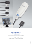
1
EN
user's manual
10014593_7
TABLE OF CONTENTS
Chapter A GENERAL
1
INTRODUCTION TO PLANMECA ROMEXIS ..................................... A-1
1.1
1.2
1.3
1.4
1.5
1.6
1.7
1.8
1.9
1.10
1.11
Brief Introduction to Digital Imaging ...................................................................A-2
Securing the Image Data ...................................................................................A-3
Acquisition .........................................................................................................A-3
Settings ..............................................................................................................A-3
Archiving ............................................................................................................A-4
Processing .........................................................................................................A-5
Measuring ..........................................................................................................A-5
Annotation ..........................................................................................................A-5
Printing ...............................................................................................................A-5
DICOM Functionality ..........................................................................................A-6
Disclaimer ..........................................................................................................A-6
2
ROMEXIS MODULES .......................................................................... A-7
3
STARTUP ............................................................................................. A-8
Chapter B PATIENTS AND FILES MODULE
1
PATIENT SELECTION AND MANAGEMENT ..................................... B-1
1.1
1.2
1.3
1.4
1.5
1.6
1.7
1.8
1.9
1.10
1.11
1.12
2
Patient Search ...................................................................................................B-1
Patient List .........................................................................................................B-2
Opening Patient Record ....................................................................................B-2
Demographics ....................................................................................................B-2
Adding and Editing Patients ...............................................................................B-3
Editing Patient Information .................................................................................B-3
Assigning Patient ...............................................................................................B-4
Finding Assigned Patients .................................................................................B-4
Adding Template Patients ..................................................................................B-4
Adding Virtual Patients ......................................................................................B-5
Inactivating Patients ...........................................................................................B-5
Find Patient by Image ........................................................................................B-5
DICOM QUERY / RETRIEVE (OPTIONAL) ......................................... B-6
Chapter C 2D IMAGING MODULE
1
IMAGING MODULE .............................................................................. C-1
1.1
1.2
1.3
1.4
1.5
1.6
1.7
1.8
1.9
1.10
1.11
User’s Manual
Toolbars ............................................................................................................ C-1
Image Browsing and Viewing ........................................................................... C-2
DICOM Media Storage (DICOMDIR) ................................................................ C-8
Image Acquisition ........................................................................................... C-11
Image Processing ........................................................................................... C-20
Image Studies ................................................................................................. C-29
Moving Image to Another Patient ................................................................... C-30
Inactivating Image ........................................................................................... C-30
Copy image to Clipboard ................................................................................ C-30
Printing Images / Print Editor .......................................................................... C-30
DICOM Print (optional) ................................................................................... C-38
Planmeca Romexis 1
TABLE OF CONTENTS
1.12 DICOM Storage & Storage commitment (optional) ......................................... C-38
Chapter D 3D IMAGING MODULE
1
3D VOLUMES ....................................................................................... D-2
1.1
1.2
2
3D EXPLORER ..................................................................................... D-3
2.1
2.2
2.3
3
Adjusting axial slices ....................................................................................... D-35
Adjusting panoramic slices ............................................................................. D-35
Cross Sectional Slide Bar ............................................................................... D-35
Adjust .............................................................................................................. D-36
Panoramic ....................................................................................................... D-37
Nerve .............................................................................................................. D-39
3D Rendered view .......................................................................................... D-40
IMPLANT MODULE ........................................................................... D-41
5.1
6
Layer and Curve Slide Bar .............................................................................. D-29
Adjust .............................................................................................................. D-29
Panoramic tools .............................................................................................. D-31
Adjusting panoramic images ........................................................................... D-32
3D Rendered view adjustment ........................................................................ D-32
3D CROSS SECTIONS MODULE (OPTIONAL) ................................ D-33
4.1
4.2
4.3
4.4
4.5
4.6
4.7
5
3D Master Menu Toolbar .................................................................................. D-4
3D Volume Viewing ........................................................................................ D-21
Volume Adjustments ....................................................................................... D-22
3D PANORAMIC MODULE (OPTIONAL) .......................................... D-28
3.1
3.2
3.3
3.4
3.5
4
Opening a 3D volume ....................................................................................... D-2
Volume Operations ........................................................................................... D-2
Implant tools .................................................................................................. D-42
TMJ MODULE ................................................................................... D-46
6.1
TMJ Tools ...................................................................................................... D-47
Chapter E CLINIC MODULE
1
CLINIC MODULE VIEWS ..................................................................... E-2
1.1
1.2
1.3
1.4
1.5
Clinic Monitoring ................................................................................................E-3
Device Monitoring/Remote Control ....................................................................E-6
Diagnostic Log ...................................................................................................E-8
Device Summary ...............................................................................................E-9
Info View ..........................................................................................................E-12
Chapter F ADMIN MODULE
1
RESOURCE .......................................................................................... F-1
1.1
1.2
1.3
Groups Tab Sheet .............................................................................................F-1
Users Tab Sheet ................................................................................................F-4
Device Alerts ......................................................................................................F-5
2 Planmeca Romexis
User’s Manual
TABLE OF CONTENTS
2
IMAGING .............................................................................................. F-8
2.1
2.2
3
Templates ..........................................................................................................F-8
DICOM Configuration ......................................................................................F-10
LOCAL SETTINGS ............................................................................. F-15
Chapter G REPORT MODULE
1
REPORT GENERATION ......................................................................G-2
1.1
1.2
1.3
1.4
2
Image Link ........................................................................................................ G-2
Patient Link ....................................................................................................... G-2
Refresh ............................................................................................................. G-2
Print .................................................................................................................. G-2
IMAGE VIEW ........................................................................................G-3
2.1
2.2
2.3
Previous/Next Image ........................................................................................ G-3
Open Copy ........................................................................................................ G-3
Set Layout ......................................................................................................... G-4
Chapter H ROMEXIS CONFIGURATION APPLICATION
1
GENERAL SETTINGS ......................................................................... H-1
1.1
1.2
1.3
1.4
2
IMAGING .............................................................................................. H-7
2.1
2.2
2.3
2.4
2.5
2.6
2.7
2.8
3
Data folders .................................................................................................... H-19
START-UP .......................................................................................... H-22
4.1
4.2
5
Panoramic ......................................................................................................... H-7
Cephalometric ................................................................................................... H-9
Intraoral ........................................................................................................... H-10
CBVT .............................................................................................................. H-12
Display ............................................................................................................ H-13
Dental Record ................................................................................................. H-14
PlanLink & Diagnostics ................................................................................... H-16
Print ................................................................................................................ H-18
IMAGE & DATA MANAGEMENT ...................................................... H-19
3.1
4
Resources ......................................................................................................... H-1
Person .............................................................................................................. H-2
Security ............................................................................................................. H-4
Regional ............................................................................................................ H-6
Client Parameters ........................................................................................... H-22
Romexis Service ............................................................................................. H-24
SERVER PARAMETERS ................................................................... H-26
5.1
5.2
5.3
User’s Manual
Server ............................................................................................................. H-26
Database ........................................................................................................ H-27
External Communication ................................................................................. H-28
Planmeca Romexis 3
TABLE OF CONTENTS
APPENDIX A: PLANMECA PROMODEL .................................APPENDIX A-1
1
QUICK GUIDE FOR PLACING PLANMECA PROMODEL
ORDERS ............................................................................APPENDIX A-1
2
PLACING PLANMECA PROMODEL ORDERS ...............APPENDIX A-2
2.1
4.1
3D Master Menu Toolbar with Planmeca ProModel Order ...............Appendix A-2
Overview of Planmeca ProModel Order Form ..................................Appendix A-4
APPENDIX B:ROMEXIS VIEWER ............................................APPENDIX B-1
1
GENERAL .........................................................................APPENDIX B-1
2
OPENING IMAGES ...........................................................APPENDIX B-1
3
VIEWING 3D IMAGES .......................................................APPENDIX B-3
4
OPENING ADDITIONAL IMAGES ....................................APPENDIX B-3
The manufacturer, assembler, and importer are responsible for the safety, reliability and
performance of the unit only if:
- installation, calibration, modification and repairs are carried out by qualified
authorized personnel
- electrical installations are carried out according to the appropriate requirements such
as IEC364
- equipment is used according to the operating instructions
Planmeca pursues a policy of continual product development. Although every effort is
made to produce up-to-date product documentation this publication should not be
regarded as an infallible guide to current specifications. We reserve the right to make
changes without prior notice.
COPYRIGHT PLANMECA 2009-06
PUBLICATION PART NUMBER 10014593 Revision 7
4 Planmeca Romexis
User’s Manual
Chapter
A
GENERAL
1
INTRODUCTION TO PLANMECA ROMEXIS
This manual describes how to use the Planmeca RomexisTM imaging software, which is
developed to be used with the Planmeca digital X-ray units and the Intracam intraoral
video cameras. Read this manual carefully before using the system.
NOTE
The ProMax 3D X-ray unit, other digital X-ray units and Intracam camera have
separate manuals, which should be used in conjunction with this manual.
NOTE
This manual is valid with the following software versions:
Planmeca Romexis 2.2.R
Planmeca Proline software PK 5.08 / PG 5.08 or later (5.13 or later recommended)
ProMax software 1.05 or later (1.31.0 or later recommended)
Planmeca ProOne software 1.0.0 or later
Planmeca Intra software 1.20 or later
NOTE
Romexis can be used under Microsoft Windows XP, Windows Vista, Business,
Windows 2003 Server (or Windows 2000) operating systems. Romexis conforms to
Windows user interface standards. Mac OS operating systems are supported with
certain limitations.
NOTE
User organization must take care of protecting the computer and the network by
using up-to-date virus and malware protection software and firewall.
Planmeca Romexis is a registered trademark of Planmeca company. Romexis imaging
software fulfills the requirements of Directive 93/42/EEC.
Planmeca Romexis allows the user to view, enhance and archive images, and it can also
be used to take images with all the present and future Planmeca digital imaging devices.
Romexis supports all the basic functionality required to view and manipulate images as
well as offers full support for multiple users on a common image archive that can be
located on a network server.
Special attention has been paid to keep the operation of the Romexis system as simple as
possible. However, it is important to realize that no computer system can be operated
continuously and successfully without competent software and hardware support.
Especially in mission critical applications, such as the archival of patient images, adequate
care must be taken so that the continuous operation of the system is ensured. This
includes, but is not limited to, ensuring that hardware and software support is available,
phone help and user training has been organized and that the backing up of patient data
has been arranged. It is recommended that a competent system integrator service is
engaged for this purpose.
User’s Manual
Planmeca Romexis A-1
INTRODUCTION TO PLANMECA ROMEXIS
1.1
Brief Introduction to Digital Imaging
Digital images are composed of small dots called pixels, much like photos in a newspaper.
The size of each pixel sets an absolute upper limit on what can be observed. See the table
below for the pixel sizes and corresponding theoretical maximum resolutions. Note that
because of the magnification inherent in all projection X-ray techniques, the theoretical
resolution at the object level is slightly higher.
Table 1:2D images
Pixel size
Sensor resolution
Image resolution
DIMAX2/3 normal
resolution mode
132 µm
3.8 lp/mm
4.5 lp/mm (5.5*)
DIMAX2/3 enhanced
resolution mode
99 µm
5.0 lp/mm
6.0 lp/mm (7.3*)
DIMAX2/3 high resolution
mode (pan)
*Transversal slicing mode
66 µm
7.6 lp/mm
9.0 lp/mm (11.0*)
DIXI2/3 normal resolution
mode
38 µm
13.2 lp/mm
13.2 lp/mm
DIXI2/3 high resolution
mode
19 µm
26.3 lp/mm
26.3 lp/mm
Device
Table 2:3D volumes
Voxel
size
Voxel
count
Calculated
resolution
File size
Exposure
time
High resolution
150 x 150
x 150 µm,
isotropic
501 x 501
x
501~125
million
3.1 lp/mm
250 MB
21 s
Normal resolution
150 x 150
x 150 µm,
isotropic
501 x 501
x
501~125
million
3.1 lp/mm
250 MB
15 s
Low dose
300 x 300
x 300 µm,
isotropic
256 x 256
x 256
~16.8
million
1.55 lp/mm
31 MB
15 s
Large view
(stitched)
300 x 300
x 300 µm,
isotropic
Variable
1.55 lp/mm
Variable
Variable
Imaging mode
Image sizes:
for dentition: diameter 80 mm x height 80 mm
for mandible or maxilla: diameter 80 mm x height 50 mm
for 3rd molar or molar implant: diameter 40 mm x height 50 mm
*stitched volumes up to diameter 160 mm x height 110 mm
A-2
Planmeca Romexis
User’s Manual
INTRODUCTION TO PLANMECA ROMEXIS
Image dynamics
Each pixel in an image is represented by a numerical value in the computer memory.
Because of the numerical (nonphysical) nature of the image, the brightness and contrast
of the image can be altered and various image enhancement operations can be performed
which are not normally possible with film images. That is one of the main advantages of
digital imaging, but it is also necessary to understand this and keep it in mind when using
manipulated images for diagnosis. The numerical nature of the image also sets an upper
limit to the detectability of contrast differences (differences in radio translucency) in digital
images. This contrast resolution is expressed in terms of number of bits used in capturing
and storing the image or in number of gray levels that the system can record. See below
for values of Planmeca equipment:
Device
DIMAX (all modes)
Number of bits
12
Promax 3D (all modes)
Gray levels
4096
12 (15 bit raw processing)
4096
Note that although most computer screens can display only 256 (8 bit) or less gray levels
and although it has been shown that the human eye can barely differentiate contrast
differences in the order of 1/32 - 1/64 (5/6 bits), the human eye automatically adapts to the
lightning conditions, and this together with proper use of the light box makes it possible to
detect smaller variations in film contrast. Thus it is necessary to capture and record
images at higher contrast resolution than 256 grey levels (8 bits). More contrast latitude
also allows more variations in exposure factors (kV/mA).
IMPORTANT SAFETY NOTICE!
Image processing can significantly alter the visibility of both large and small
structures (i.e. bone loss and caries), which may result in either too many false
positive or false negative findings, if care is not taken.
1.2
Securing the Image Data
Romexis uses database system for storing patient data and image meta information.
Image data is stored onto the file system as individual files. Both the database and the
image data in the file systems need to be backuped and stored in a safe place. Note that
Planmeca claims no responsibility for the end users’ data security or for any malfunction in
the computer system that may lead to data loss.
1.3
Acquisition
The system is designed to automate the acquisition of images with minimum intervention
from the user. Provided that the user has selected the correct patient in Romexis software,
the acquisition (taking an exposure) and archiving of the image is almost exactly the same
as with conventional film based imaging systems, except that archiving is fully automated
and no film processing is necessary. The employed exposure technique is automatically
stored with each image.
1.4
Settings
Romexis provides various settings for the user to choose from. A range of parameters and
other options can be set to permit control over the main procedures. The default settings
have been chosen for a typical Romexis environment. If required, they can easily be
changed in the Romexis Configuration application.
User’s Manual
Planmeca Romexis A-3
INTRODUCTION TO PLANMECA ROMEXIS
1.5
Archiving
The archiving of images in Romexis is organized under patient names. The image data is
stored in the file system. The exposure values and basic patient data is stored in a
database. Multiple users can store and retrieve (different) images to and from the system
simultaneously.
1.5.1
Long Term Archive
Long Term Archive (LTA) allows old images to be moved to a more permanent storage
based on their age. For more information on Romexis Long Term Archive feature please
see Image Management under Romexis Configuration application. Please note that Long
Term Archive is not a backup system but appropriate backups should be maintained in
addition to LTA media.
Disk Space Requirements for 2D Images
The following gives approximate disk space requirements for different image formats:
Without compression With JPEG1 compression
Format
DIMAX2/3 normal resolution, panoramic
5.0 MB
0.8 MB
DIMAX2/3 normal resolution, cephalometric
7.0 MB
0.95 MB
8.9 MB
1.1 MB
2,
DIMAX2/3 enhanced resolution panoramic
DIMAX2/3 enhanced
DIMAX2/3 high
resolution2,
resolution2,
cephalometric12.5 MB
20 MB
2.2 MB
Dixi2/3 B0 normal resolution
560 kB
180 kB
Dixi2/3 B1 normal resolution
940 kB
310 kB
Dixi2/3 B2 normal resolution
1.3 MB
430 kB
2.2 MB
720 kB
resolution2
3.8 MB
1.2 MB
2
5.2 MB
1.7 MB
Dixi2 B0 high resolution
Dixi2/3 B1 high
2
panoramic
1.9 MB
Dixi2/3 B2 high resolution
IMPORTANT SAFETY NOTICE!
JPEG conversion is a so called lossy compression, the use of which can lead to
loss of image detail and it cannot be guaranteed that the diagnostic value of the
compressed image is equivalent to the original image. While several studies (see
e.g. IADMFR/CMI´97 Advances in Maxillofacial Imaging: The loss of image quality in
panoramic radiography using image compression, C.G.H Sanderink et al.) indicate
that the loss of data may be insignificant, Planmeca cannot guarantee that it is safe
to use compressed image data for diagnostic purposes.
1. The actual achievable values depend on the individual image.
2. Because of the extensive disk space requirements and the additional X-ray radiation needed to achieve the
same (low) level of noise (quantum mottle), the user should carefully evaluate the advantages of using the
enhanced/high resolution mode.
A-4
Planmeca Romexis
User’s Manual
INTRODUCTION TO PLANMECA ROMEXIS
Disk Space Requirements for 3D Images
Dimensions
Mode
Format
Size
3D volume 8x8
High resolution
DICOM 3.0 format
(multi frame)
250 MB
3D volume 8x8
Low dose
Normal resolution
DICOM 3.0 format
(multi frame)
31 MB
1.6
Processing
Note that some of the image processing operations radically alter the appearance and
possibly the diagnostic value of the image. However, it is always possible to restore the
image to its original state or undo modifications one by one.
1.7
Measuring
The measurement tools allow both geometric and relative intensity (i.e. radiotranslucency
or brightness/contrast) measurements to be made.
When performing geometric measurements it should be noted that image processing
operations (even just adjusting the brightness/contrast) can alter the apparent geometry of
the objects in the image. Also because of the normal distortions (most notably varying
magnification) associated with normal projection X-ray imaging the measurements must
be based on known reference objects in the image. For this purpose a calibration tool is
provided in the Romexis software.
When performing intensity measurements it should be noted that after certain image
processing operations the relative intensities of the objects may be affected by their
neighboring objects, which may affect the reliability of e.g. bone density measurements
with the help of a calibration step wedge. The only image processing operations
guaranteed NOT TO CHANGE the relative intensities so that measurements are
independent of the measurement position, are the brightness/contrast and level
adjustment operations. No guarantee can be given between the intensity measurements
of two different images.
1.8
Annotation
Images can be annotated with markers and text. These annotations appear as an overlay
on the image and can thus be turned on and off at will, they do not affect the actual image.
1.9
Printing
Romexis supports DICOM compatible printers and Windows compatible printers.
User’s Manual
Planmeca Romexis A-5
INTRODUCTION TO PLANMECA ROMEXIS
1.10
DICOM Functionality
Romexis supports following DICOM (Digital Imaging and Communications in Medicine)
services:
•
DICOM Storage SCU (optional)
•
DICOM Storage Commitment SCU (optional)
•
DICOM Query Retrieve SCU (optional)
•
DICOM Worklist SCU (optional)
•
DICOM Print SCU (optional)
•
DICOM Import, single and multi frame
•
DICOM Export, single and multi frame
•
DICOMDIR Media Storage
DICOM functionality is described in chapters “PATIENTS AND FILES MODULE”, “2D
IMAGING MODULE” and “3D IMAGING MODULE”. DICOM configuration is described in
section 2.2 “DICOM Configuration” on page 10 in chapter “ADMIN MODULE”.
1.11
Disclaimer
IMPORTANT SAFETY NOTICE!
Note that Planmeca claims no responsibility for the end user’s data security
or for any malfunction in the computer system that may lead to data loss.
Since image processing and digital subtraction radiography can
significantly alter the visibility of both large and small structures (i.e. bone
loss and caries), which may result in either too many false positive or false
negative findings, Planmeca claims no responsibility for the software use,
actions or diagnoses made by the end-user.
The qualities of the monitor can strongly affect the image quality. The
monitor qualities change when it gets older.
Never try first to correct under/overexposure by taking a new image with
new exposure values. This should be done by adjusting the gamma and/or
contrast/brightness to the right level. If these adjustments do not help, only
then take a new image.
Cone beam computed tomography (CBVT) imaging is based on complex
mathematical algorithms that produce high fidelity images, however various
sources may cause imaging artefacts that may lead to incorrect diagnoses if
not properly interpreted. Image interpretation should only be done by a
competent person who is familiar with the CBVT imaging capabilities,
limitations and artefacts of the ProMax 3D.
A-6
Planmeca Romexis
User’s Manual
ROMEXIS MODULES
2
ROMEXIS MODULES
The Romexis software is built around different software modules. Each of them is
designed to perform special tasks. These modules can be accessed through the navigator
buttons located in the vertical toolbar on the left edge of the screen.
1. Patient module providing patient selection and management
2. Files module holding demographics
3. Dental record module (optional)
4. Imaging module for X-ray and other imaging needs
5. 3D Imaging module for ProMax 3D images (optional)
6. Clinic management (optional)
7. Report module
8. Admin module
The navigator toolbar is always visible and it can be used for navigating between the
modules at any time during the work process.
NOTE
User’s Manual
The visibility of the Romexis modules and functions are controlled by license and
user rights. Depending on the installed licence and user rights the functionality
described in this manual can vary.
Planmeca Romexis A-7
STARTUP
3
STARTUP
After startup the user is presented with a login window if so defined in the Romexis
Configuration application (see chapter “ROMEXIS CONFIGURATION APPLICATION”).
The appearance of the Login window may differ from the above depending on the settings
configured by your administrator. After a successful login Romexis enters the Patient
module where patients are managed. The name of the current user is shown in the title
bar.
A new login is initiated by clicking the Login button.
The Logout button closes all patient files and logs out the current user.
NOTE
A-8
If a new Login is performed while another user is currently logged in, all patient
records are closed but the current views will be remembered and will be shown
when a patient is next accessed by a user. This function allows multiple authorized
personnel to conveniently view and modify a patient's status using their own
credentials. If the Logout feature is used no views will be remembered and the
patient data will be opened with default view when next time accessed.
Planmeca Romexis
User’s Manual
Chapter
B
PATIENTS AND FILES MODULE
1
PATIENT SELECTION AND MANAGEMENT
After startup the Patient module opens automatically. In the Patient module you can:
1. Search for a patient in the database.
2. Open a patient file.
3. View and sort a list of patients.
4. Add new patients.
5. Edit patient information.
6. Assign patients to a certain doctor/student.
7. Search for patients assigned to a certain provider.
8. Create template patients.
9. Create virtual patients.
10. Inactivate patients.
1.1
Patient Search
Patients can be searched by ID or by name. To search a patient by ID, enter the patient ID
in the text field and click the Find button. To search patients by their name choose the
option Find by name from the drop-down menu on the left of the search field. Enter the
patient’s name in Last name, First name format into the search field and touch the Enter
key or click Find to make matching patients appear in the patient list.
To view all patients saved in the database use the * sign as the search term.
NOTE
If a partial name is entered Romexis will return all patients whose last name begins
with that partial string. In case you want to search patients by their first name
replace the last name with the wild card *.
Examples:
Doe, John
all patients with the last name Doe and first name John
S
all patients whose last name starts with the letter S
Smi
all patients whose last name starts with ‘Smi’, e.g. Smith
and Smiley
Van Cogh
all patients with the last name Van Cogh
*, Paul
all patients whose first name is Paul
Patients can also be searched by a captured image, see section 1.12 “Find Patient by
Image” on page 5.
User’s Manual
Planmeca Romexis B-1
PATIENT SELECTION AND MANAGEMENT
1.2
Patient List
Patients in the patient list can be sorted by ID, name, birth date, age, gender, phone
number, the number of assigned providers and type (for virtual and template patients) by
clicking the respective column title.
1.3
Opening Patient Record
After the patient search click the patient name in the patient list and click the Select button
(or double-click the patient name). You are presented with a dialog where you are required
to define a reason for opening the patient record. This dialog can be set optional in the
Romexis Configuration application.
Select the appropriate reason and click OK. Romexis automatically opens the Files
module. The reason for opening a patient record is saved and displayed in the dental
record under the patient case history.
The name of the active patient record is always visible in the upper right corner of the
screen. Several patient records can be open at a time but only one of the open records is
active at a time. To close the active patient record click the Close Patient button next to the
patient name. The open patient records can be viewed using the drop-down menu (click
the name), and the active patient record can be modified by selecting another patient from
the drop-down list.
B-2
Planmeca Romexis
User’s Manual
PATIENT SELECTION AND MANAGEMENT
1.4
Demographics
The Demographics tab sheet contains all patient demographic information and is
automatically selected when creating a new patient or editing an existing one. Click the
Edit patient button to edit demographic information and the Save patient button to save
changes.
Please note that the changes are not saved automatically. Click the Save patient button to
save your changes.
1.5
Adding and Editing Patients
To create a new patient record click the Add Patient button which will take you to the Files
module. In the Files module you can enter the patient’s Demographic information and add
face photo to patient. The compulsory fields are Person ID, First name and Last name.
Click the Save Patient button to save the patient record into the database. Please note
that the changes are not automatically saved but the Save Patient button must be used. A
new patient search has to be made to view the newly created patient on the patient list.
NOTE
1.6
All patient information is managed in the Files module. Romexis automatically
opens the Files module when the Add patient button is clicked. Existing patients are
also modified using this module.
Editing Patient Information
To edit the patient information of an existing patient click the Edit Patient button to enter
the patient demographics view. Edit the information as required and click Save.
User’s Manual
Planmeca Romexis B-3
PATIENT SELECTION AND MANAGEMENT
1.7
Assigning Patient
Patients can be assigned to providers with the Assign patient button. Select the patient
you want to assign from the list and click the Assign patient button to open a list of
providers, then choose the provider you want to assign the patient to. Patients can have
one primary provider and several secondary providers. In case a patient already has one
provider and the Assign patient button is clicked again the following dialog appears.
This allows the user to reassign the patient to a new Primary provider or assign new
Secondary provider(s) for the patient.
To see the provider assigned to the patient click the
button.
The number of the providers assigned to the patient is shown in the patient list.
1.8
Finding Assigned Patients
To retrieve all patients that are assigned to the current user the Find assigned button can
be used to list these patients from the database.
1.9
Adding Template Patients
For educational purposes Romexis offers a combination of template and virtual patients.
The idea of template patients is that supervisors can create virtual patient cases for
students to practice on in simulation laboratory. Thus template patients are not real
patients but represent possible patient cases that can then be cloned into virtual patients
for the students to actually work on. The supervisor can define a template patient’s oral
status, medical/dental history and import images to the template patients.
Template patients are created by clicking the Add template button. Before students can
actually start working on a template patient, it needs to be cloned into a virtual patient that
can then be assigned to individual students.
NOTE
B-4
Template patients can be differentiated from other patients by a ‘Template’ entry in
the Type column.
Planmeca Romexis
User’s Manual
PATIENT SELECTION AND MANAGEMENT
1.10
Adding Virtual Patients
After the supervisor has created a template patient, virtual patients for students can be
created. The idea is that each student has their own virtual patient(s) to work with, but all
students start from the same template patient, that is, with the same clinical problem set.
To create a virtual patient select the template patient from the patient list and click the Add
virtual button. It may be a good idea to name each virtual patient so that the name also
indicates the student name, i.e. Jane’s Child Patient.
NOTE
1.11
Virtual patients can be differentiated from other patients by entering ‘Virtual’ in the
Type column.
Inactivating Patients
A patient can be removed from the patient list by clicking the Inactivate button. All patient
information with images is however preserved. Patient information can be reactivated or
permanently deleted in the Romexis configuration application, see chapter “ROMEXIS
CONFIGURATION APPLICATION”.
1.12
Find Patient by Image
Patients can also be searched by the image type, date and image comments. Define the
search criteria and click the Find button. The patients that match the search criteria appear
in the list. Open the patient by selecting the patient from the list and click the Select button.
User’s Manual
Planmeca Romexis B-5
DICOM QUERY / RETRIEVE (OPTIONAL)
2
DICOM QUERY / RETRIEVE (optional)
DICOM Query Retrieve SCU (Q/R) service is used for retrieving images from DICOM
PACS servers. Images can be first queried and then selected for retrieval to the local
storage. Once retrieved they can be processed independent of the remote server. Use
DICOM Storage function to send processed images back to the DICOM PACS server. Use
Query button to list images for a patient at the Patient Root Level, Retrieve button to
retrieve the selected images, and Study button to list images at the Study Root Level..
B-6
Planmeca Romexis
User’s Manual
Chapter
C
2D IMAGING MODULE
1
IMAGING MODULE
The Imaging module is used for X-ray image and photo capturing, processing, and storing.
The centre of this module is used by the image viewer to show images that are captured or
opened by the user. The image viewer automatically places images into a layout
attempting to maximise their viewable size. The layout can be modified by clicking the
Layout button (see section 1.2.6 “Layout Button” on page 4 for more information on
layouts).
The bottom of the Imaging module is normally employed by the image browser that allows
the user to open images into the image viewer by double-clicking on them. The image
browser can be hidden and made visible using the Browser button (see section 1.2 “Image
Browsing and Viewing” on page 2 for more information).
NOTE
1.1
A patient needs to be selected before the Imaging module can be accessed.
Toolbars
There are three types of toolbars and icons in the Imaging module user interface:
1. The top toolbar contains buttons for launching image capture, export/import and
general layout options.
2. The vertical toolbar at the far right contains the image processing and annotation tools.
When using these tools any function (i.e. zooming) can be applied on all open images
in the image viewer (not on images in the image browser).
3. Each open image has its own horizontal toolbar image above the image. These viewing
and processing tools affect only that respective image. The vertical image toolbar can
be opened using the wrench button. See 1.5.2 “Image Toolbars” on page 21 for more
information.
User’s Manual
Planmeca Romexis C-1
IMAGING MODULE
1.2
Image Browsing and Viewing
1.2.1
Image Browser
The image browser is opened by default in the lower part of the screen when the Imaging
module is opened. The image navigator can be opened and closed by clicking the Image
Browser button from the top toolbar. The image browser shows all the images the patient
has, with different image types in their respective categories. The visibility of the images in
each category can be controlled with the set of buttons below the navigator.
To clear the image selection click the Clear button.
The Refresh button can be used to update the image view and recall any new images.
This function is especially helpful in case the patient file is open in one workstation and
images are captured simultaneously to the same patient in another workstation.
The number in parenthesis indicates the number of images in each category.
The intraoral images are arranged by the tooth number in case the tooth numbers have
been defined to the images. The number above or below a tooth number indicates how
many images the patient has where that tooth is shown. The intraoral images can be
further sorted with checkboxes for type or by radio buttons for capturing date.
Clicking the intraoral image thumbnail opens the topmost image.
Clicking on a tooth number opens all intraoral images of that tooth in the bigger preview on
the left.
Intraoral images which have no tooth number defined are located in the “Other IO”
category.
C-2
Planmeca Romexis
User’s Manual
IMAGING MODULE
1.2.2
Opening an Image
Images can be opened directly by double-clicking on them in the image browser, or by
selecting them in the image browser and then clicking the View Selected button. Images
can be closed by clicking the
icon in the image’s horizontal toolbar.
1.2.3
Opening a Study
A study is a collection of related images of one patient. Studies can be viewed with the
Study tab. A list of existing studies appears, and by clicking the name of a study it is
previewed in the image navigator. To open an image from the study (for adjustment etc.)
select the desired image in the preview and click the View Selected button. To view all
images in the study click the View Study button. See section 1.6 “Image Studies” on page
25 for more information on how to work with studies in Romexis.
1.2.4
Creating a New Study
An empty study can be created with the
button.
Select the template you want to use to create a new study.
For information on how to add images to an empty study see section 1.6.3 “Adding Image
to Study” on page 26. Please note that to capture X-rays directly into a template you
should follow the instructions in section1.4.1 “Capturing Intraoral Images” on page 10 in
this chapter.
1.2.5
Closing All Images
All open images can be closed by clicking the
User’s Manual
button.
Planmeca Romexis C-3
IMAGING MODULE
1.2.6
Layout Button
Images open in the viewer can be arranged into a temporary layout with the
button.
These layouts are also used to position multiple images for printing. If the same layout is
used frequently, it is advisable to define and use a study template instead. See the
previous sections for using studies and chapter “ADMIN MODULE” (section 2.1
“Templates” on page 8) for how to define templates.
1.2.7
Importing Images
Click the
button and browse to the image file to be imported. Several images can
be imported at the same time by holding down the Shift or Ctrl key while selecting files.
C-4
Planmeca Romexis
User’s Manual
IMAGING MODULE
After selecting the file(s) and clicking Open a window for setting image parameters
appears. Select the image type, and, for intraoral images, also define the tooth numbers.
For multiple images you are prompted separately for each image.
If you click Cancel to skip a single image when importing multiple images, Romexis will
ask: “Continue importing images?”. Click Yes if you want to continue importing the rest of
the images.
It is also possible to crop the image when importing. Click the Crop button, click and drag
the mouse on the top of the image to specify the area of interest. A green rectangle will
appear to denote a selection in process. When the mouse button is released the rectangle
will turn red to denote a successful selection.
User’s Manual
Planmeca Romexis C-5
IMAGING MODULE
1.2.8
Exporting Images
Open the image(s) or study that needs to be exported. Click the Export
button.
Select the Processed images option to export the image(s) in 8 bit with all enhancements
applied, or select the Original images option to export original image(s) (8 or 16 bits,
depending on the original capturing mode).
If you are exporting multiple open images or a study, you can either export the images as
multiple files or as one single image (all images merged into a single file) by selecting the
All images in one file option. When exporting as multiple files, a sequence number and file
extension will be automatically added to the file name specified.
If you want to create a text file that includes image related information enable the option:
Create patient and image information file.
If you want to embed the image information directly on the exported image enable the
option: “Burn” patient information to the exported file.
Click OK to export the file(s) as specified.
1.2.9
DICOM Import
DICOM 3.0 format images can be imported using the DICOM Import function similar to
other images. See section 1.2.7 “Importing Images” on page 4 for more information on the
import process.
1.2.10 DICOM Import with Patient Data
To import a DICOM image and to create a new patient from the information included in the
DICOM file, use the DICOM with Patient option available in the File menu.
C-6
Planmeca Romexis
User’s Manual
IMAGING MODULE
1.2.11 DICOM Export
Open the images or study that needs to be exported. Click the DICOM Export
button to open the export dialog below.
Select the Processed images option to export the image(s) with all enhancements applied,
or select the Original images option to export original image(s) as they were captured. In
DICOM Export the original bit value is always preserved.
Anonymize File(s) removes all patient information from the exported DICOM image(s).
If you want to create a text file that includes image related information enable the option:
Create patient and image information file.
Click OK to export the DICOM file(s) with relevant patient information included.
1.3
DICOM Media Storage (DICOMDIR)
The DICOMDIR file format specifies a standard way to organize storage and retrieval of
DICOM format file sets to and from offline storage such as a CD. A compatible DICOMDIR
CD, for example, contains description and access information for all the studies on that
CD. Planmeca Romexis supports both DICOMDIR import and export functions.
Before you start using DICOMDIR import or export, make sure that the user has
appropriate import and export images permissions granted in the Romexis Administration
module. (See 1.1 “Groups Tab Sheet” on page 1 in chapter “ADMIN MODULE” for more
information on permissions.)
1.3.1
DICOMDIR Import
DICOMDIR Import allows you to import a set of multiple patients with their patient
information and images from DICOMDIR into Romexis.
To start importing images from a DICOMDIR, click on the DICOMDIR Import
button or use the File – DICOMDIR Import menu option:
User’s Manual
Planmeca Romexis C-7
IMAGING MODULE
First browse to and select the DICOMDIR file to be imported using the Browse button.
When an appropriate DICOMDIR file is selected, a tree list with images and thumbnails is
populated. The tree list on the top left shows each patient in the DICOMDIR and their
images in a hierarchical list. When an image entry is selected in the tree list, its DICOM
tags will be displayed at the bottom and its thumbnail will be highlighted on the right.
To import images, tick them in the tree list and deselect any unwanted patients and
images. After you have selected all desired images, click Import to have new patients
created when necessary, based on the selection and the selected images imported to
them. If a patient with a same name as the one being imported is already found in the
database, Romexis will ask if you are sure you want to import the images to that patient
instead of creating a new one. Verify that the correct patient is in question before
continuing.
All images that have an image UID (Unique Identifier) already in the database will be
rejected, unless you have enabled the Allow duplicate UIDs option at the bottom of the
dialog.
1.3.2
DICOMDIR Export
DICOMDIR Export allows you to export a set of multiple patients with their patient
information and images into a DICOMDIR file structure. A DICOMDIR Directory
information file is saved as specified in the Export To dialog and all exported DICOM
image files are stored into its adjacent subfolder titled \images.
To start exporting patient information and images from a DICOMDIR, open the Import
dialog by clicking the DICOMDIR Export
button or, if no patient is selected, use
the File – DICOMDIR Export menu option:
C-8
Planmeca Romexis
User’s Manual
IMAGING MODULE
First define the DICOMDIR file to be created and exported into using the Export To button.
In the opening Export To dialog you can browse to the correct folder and define a filename
for the new DICOMDIR file.
After you have defined the DICOMDIR file, add patients into the tree list at the top left by
using the Add Patient button. In the dialog that opens you can search and select a patient
to be added into the DICOMDIR. Select a patient in the list and click OK to add it to the
tree list. You can repeat the Add Patient task to add multiple patients.
When patients are added into the DICOMDIR they will show in the tree list with all their
studies and images in a hierarchical list. You can browse the item DICOM tags and
thumbnails by highlighting an item and referring to the bottom and right edges of the
dialog. Use the tick marks next to each item to include or exclude them from the final
DICOMDIR file.
The Save Processed Image option at the bottom of the dialog allows you to export images
with all image processing operations merged into the image as they have been defined in
Romexis.
Save Annotations applies any annotations made in Romexis into the exported images.
Anonymize File(s) removes all patient information from the exported DICOM image(s).
Export with Romexis Viewer option places a copy of Romexis viewer into the same folder
with the DICOMDIR file-set. The contents of the export folder can then be written onto a
CD using any 3rd party tools and handed to a customer or referrer. Please note that it is
possible to open DICOMDIR file-sets in Romexis Viewer 2.0 version and later.
User’s Manual
Planmeca Romexis C-9
IMAGING MODULE
Burn DICOMDIR and Romexis Viewer to CD option allows you to write the DICOMDIR
and a copy of the Romexis Viewer directly onto a CD. Make sure you have an empty
writable media in the drive before attempting to use this option.
When forwarding the DICOMDIR file-set, make sure you include the DICOMDIR Directory
information file specified in the Export To dialog and the adjacent \images subfolder.
1.4
NOTE
1.4.1
Image Acquisition
The ability to capture X-ray images is defined in the user rights (see chapter“ADMIN
MODULE”). In case a user does not have the right to capture images without
approval the image acquisition buttons are disabled until an Image acquisition
request for that current user/active patient/image type combination has been
approved.
Capturing Intraoral Images
Intraoral images can be captured either as single images or into study templates
containing a predefined set of multiple images.
To capture single images click the
button to initiate image capture mode. The
Intraoral Exposure Window appears. When the X-ray unit is in ready state a message
Waiting for exposure appears on top of the window. Prepare the patient for exposure and
select exposure parameters. See Planmeca Intra X-ray manual for more information. You
can now expose X-rays in the normal way.
After the exposure a message stating Saving the image appears and the image is
automatically stored into the database. Define the tooth numbers and sensor orientation
and capture the next exposure, or click Done to return to the Imaging module when all
exposures have been captured.
To capture intraoral images into a study template click the
C-10
Planmeca Romexis
button.
User’s Manual
IMAGING MODULE
Select the desired study template from the list. At the beginning of the list there are empty
templates and at the bottom of the list there are studies with dates that already include
images captured earlier.
While capturing images using a study Romexis walks through the template in a predefined
order, denoting the current image to be captured by a blue border around the slot. Follow
the tooth numbering and sensor orientation as shown on the top, also predefined in the
template.
User’s Manual
Planmeca Romexis C-11
IMAGING MODULE
You can cancel the process with the Cancel button in which case the captured images are
saved and the incomplete study is preserved for later use.
After all the images have been captured click Done.
1.4.2
Capturing Panoramic Images
To capture a panoramic image click the
button to initiate panoramic image capture
mode. The Panoramic Exposure window appears. When the X-ray unit is in ready state a
message Waiting for Ready appears on top of the window. Prepare the patient for
exposure and select the exposure parameters and drive the X-ray to the ready position.
Refer to your Planmeca panoramic X-ray unit’s user’s manual if uncertain.
When the panoramic unit is in ready position a message stating Waiting for Exposure
appears on top of the window. You can now expose the X-ray as normal. After the
exposure a message stating Saving the image appears and the image is automatically
stored into the database.
Click Done when the exposure has been taken to return to the Imaging module.
NOTE
C-12
The L sign denotes the left side of the patient.
Planmeca Romexis
User’s Manual
IMAGING MODULE
1.4.2.1 SmartPan Layer Panoramic Capture
General
The Planmeca Promax 3D can take both 3D and 2D images. Available 2D imaging modes
are panoramic, bite-wing and sinus exposure modes.
For the 2D images acquired with SmartPan, only the pixel size 127µm
m is available.
Image capturing Standard Pan (including BiteWing ja Sinus modes)
To capture a panoramic image click this
button to initiate panoramic image
capture mode. The Panoramic Exposure window appears. When the X-ray unit is in ready
state a message Waiting for Ready appears on top of the window. Prepare the patient for
exposure and select the exposure parameters and drive the X-ray to the ready position.
Refer to your Planmeca panoramic X-ray unit’s user’s manual if uncertain.
When the panoramic unit is in ready position a message stating Waiting for Exposure
appears on top of the window. You can now expose the X-ray as normal.
After exposure an image (Layer 0) appears on the screen. By clicking the left and right
arrows on both sides of the Adjust Smart Pan bar, new layers are processed (-4, -3, -2, -1,
0, 1, 2, 3, 4) which can then be browsed through the menu. To select layers click Save
when the desired layer appears on the screen. To open the selected layers in the Romexis
2D Image processing view click Done.
User’s Manual
Planmeca Romexis C-13
IMAGING MODULE
1.4.3
Capturing Cephalometric Images
To capture a cephalometric image click the
button to initiate the cephalometric
image capture mode. The Cephalometric Exposure window appears. When the X-ray unit
is in ready state a message Waiting for Ready appears on top of the window. Prepare the
patient for exposure and select exposure parameters and drive the X-ray to ready position.
Refer to your Planmeca cephalometric X-ray unit’s user’s manual if uncertain.
When the cephalostat unit is in the ready position a message stating Waiting for Exposure
appears on top of the window. You can now expose the X-ray as normal. After the
exposure a message stating Saving the image appears and the image is automatically
stored into the database.
Click Done when the exposure has been taken to return to the Imaging module.
1.4.4
TWAIN
TWAIN is a cross-platform interface for acquiring images captured by scanners, digital
cameras or frame grabbers. The manufacturer of the TWAIN device must provide a
Source Manager and TWAIN Data source for your device to work with Romexis.
Romexis supports the current TWAIN_32 standard. Refer to your device manufacturer’s
documentation for information on the availability of TWAIN_32 source modules.
C-14
Planmeca Romexis
User’s Manual
IMAGING MODULE
1.4.5
TWAIN Capture
If you are using the TWAIN device for the first time, check that you have the correct
TWAIN source device selected by clicking the TWAIN Setup icon to bring up the TWAIN
Settings dialog. Then click the Select TWAIN Source button and choose the correct device
from the list.
To acquire an image from the TWAIN device click the Acquire image using TWAIN button
to start the TWAIN interface. Refer to the scanner/camera user’s manual for information
on how to proceed with the device you are using.
1.4.5.1 TWAIN Source Settings
User’s Manual
•
Wait for TWAIN driver Close: Specifies whether a Close command is expected from the
TWAIN driver to signal the end of scanning session. If disabled, only single scan is
expected to be received. When enabled, multiple scans can be made in one session
which are all returned in one batch when the scanning dialog is closed. If the
scannersoftware is capable of scanning multiple images in one session this setting should
be enabled.
•
Prefer Memory Transfer: Enables Memory Transfer instead of Native Transfer mode.
Refer to your scanner documentation for more information on supported and/or preferred
mode. For scanning color images Prefer Memory Transfer should be enabled.
•
Show TWAIN Launch Dialog: If enabled, a dialog is shown when the scanner software
has been launched via TWAIN. On some lower end systems bringing up the TWAIN
interface can take some moments during which it may be useful to notify the user of the
process. Some virus scanning software is also known to slow down the TWAIN launch.
•
Show Import Dialog: Specify whether the Romexis image import dialog should be shown
for each imported image. The image import dialog allows the users to choose image
Planmeca Romexis C-15
IMAGING MODULE
modality, specify tooth numbers, and crop or reorient the image. If disabled each scan is
imported with default settings and modality is defined by the Default Image Type setting
below. Default Image Type: Specifies the default modality for scanned images.
1.4.5.2 TWAIN Auto Import Settings
In some cases you need to configure TWAIN Auto Import Settings to allow you to have
images automatically imported as part of the TWAIN capture. However, generally this is
not required and you can safely ignore these settings.
1.5
Image Processing
1.5.1
Vertical Toolbar
Measurement tools
Calibrate for measurement
Click the icon, draw the calibration line by holding the left mouse button
down, end the line with a right-click and the calibration window appears.
Enter the length and click OK.
NOTE! You should not use the calibration tool on CBVT snapshots
as they are automatically calibrated.
Measure angle
Click the icon, draw the angle by pressing the left mouse button down.
Measure length
Measure length over single or multiple points. Measure Length is a dual
mode button: hold down mouse button to call up mode selection between
Single measurement and polyline measurement.
Single measurement – use to measure length between 2 points (default).
Hold down left mouse button to define measurement, release mouse
button to finish.
Polyline measurement – use to measure length over multiple points.
Draw the line by pressing the left mouse button down. Release mouse
button to finish.
C-16
Planmeca Romexis
User’s Manual
IMAGING MODULE
Measurement tools
Line profile
By clicking the Line Profile icon and drawing a line to the 2D image, the
user can view the gray scale profile of the respective line. Min, Max,
Average and Standard Deviation of the line profile are also available. If
the line profile gray scale values are very near to each other, by ticking the
Relative values checkbox the variations between these values are
emhazised.
Show histogram
By clicking the Show Histogram icon the histogram of the open image/
selected region of interest is shown. A histogram is a graphical
representation of the gray scale distribution in the image/area. By default
the histogram is drawn in square root scale. Linear scale can be enabled
by ticking the Linear scale checkbox. Max, Average and Standard
Deviation of the histogram data is also available.
Show measurements, Show/hide values
User’s Manual
Planmeca Romexis C-17
IMAGING MODULE
Drawing tools
Draw Line / Polyline
Draw line over single or multiple points. Draw Line is a dual mode button,
hold down mouse button to call up mode selection between single line and
polyline drawing.
Draw single line - use to draw line between 2 points (default). Hold down
left mouse button to define line, release the button to finish.
Draw polyline - use to draw line over multiple points. Draw the line by
pressing the left mouse button down and release the button to finish.
Draw a horizontal line
Draw a vertical line
Draw an arrow
Draw curve
Draw rectangle
Draw an ellipse
Draw text
Click the icon and point with the mouse where you want to add the text.
Type the text to the opening window and click OK.
To edit the text later select the text with the Select annotations button (see
below) and then double-click the text. Edit the text and click OK.
Select/move/edit annotations
Click the icon and and take the mouse (cross inside the arrow) to the top
of the graphics. To move a graphic, select and drag it to a new position.
This tool can also be used to edit annotations by moving their control
points.
C-18
Planmeca Romexis
User’s Manual
IMAGING MODULE
Drawing tools
Delete selected annotations or measurements
Show annotations
Shows and hides annotations. Even if the annotations are hidden they are
still stored with the image.
Select annotations
When an annotation (line, arrow, circle, rectangle, curve) is selected, its
color and line width can be adjusted. Use the Select Annotation tool to
activate the annotation you want to edit. When an annotation is active you
can modify it using the Color and Width settings shown in the Image
Toolbar.
Sketch a free line
Sketch a free line for demonstration purposes.
Note! Sketch lines are not saved or stored and are lost when image
is closed.
Viewing tools
Zoom out
Zoom in
Zoom to fit
All open images are fitted to view
1:1
All open images are scaled to 1:1
User’s Manual
Planmeca Romexis C-19
IMAGING MODULE
Viewing tools
Uniform scaling for all images
Magnifier 2x
Invokes the magnifier glass (2x) on the image. The magnifier can be
moved on the image.
Show overview
When the image is zoomed in, the images can be panned with an
overview window.
Flashlight
Enables a movable square Flashlight overlay that allows regional filter for
Gamma, Contrast & Brightness, Invert, Equalize, Sharpen, and Emboss.
Use the mouse scroll wheel to adjust the size of the filter area and rightclick to switch between different filters. See also Flashlight setup below.
Flashlight setup
Similar to Flashlight function above but allows setting of Gamma, Contrast
& Brightness values. The settings are image specific. Use the mouse
scroll wheel to adjust the size of the filter area, and the radio buttons or
the right click to switch between different filters.
Pan
Image processing tools
Adjust contrast and brightness
Invokes contrast and brightness control to all open images. You can adjust
the brightness and contrast by dragging the sliders or by moving the
mouse on the image while pressing the left mouse button. Horizontal
movement changes the brightness and vertical the contrast .
C-20
Planmeca Romexis
User’s Manual
IMAGING MODULE
Image processing tools
Region of interest
Use the Region of Interest tool to specify and select the area of effect for
image processing tools and certain measurements. Use this tool together
with for example image Histogram tool to view grayscale values of a
region.
Note that it is possible to specify multiple regions and to switch between
them by using the Reqion of Interest tool. Active region is denoted in
green and inactive regions in blue color. Use Delete Measurements tool or
Delete key to delete the selected region.
1.5.2
Image Toolbars
Horizontal image toolbar
1:1
Scales the image 1:1.
Zoom in, zoom out
Show image properties
Opens the General tab under Image properties window where the tooth
numbers (for intraoral images) can be defined, the image can be rotated/
flipped and the image file info and exposure parameters can be viewed.
Show image diagnosis
Opens the image Diagnosis tab under Image Properties. Shows and
allows editing image diagnosis. Diagnosis up to 2500 characters is
supported.
User’s Manual
Planmeca Romexis C-21
IMAGING MODULE
Horizontal image toolbar
Show vertical image processing toolbar
Opens the vertical image toolbar.
Maximize the image
Close the image
C-22
Planmeca Romexis
User’s Manual
IMAGING MODULE
Vertical image toolbar
Adjust levels
Gamma curve can be adjusted by moving the green line in the histogram.
The histogram can be cut from the ends by moving the red lines. The
levels can also be adjusted by moving the mouse vertically and
horizontally on the image.
Use the small double arrow shown in the bottom left corner of the above
screenshot to reveal the advanced options.
Use the up/down arrows and the 1:1 button to scale the histogram to bring
out details. Enable Overlay result histogram to highlight the resulting
histogram and Linear scale to draw the histogram in linear scale instead of
the default logarithmic scale.
The Min, Max, Avg (Average), and StdDev (standard deviation) values
show the corresponding grayscale values in the image or in the Region of
Interest when one is active.
When pseudocolours are enabled, this dialog is also used to select
colours and to alter their balance. To do so, use the handles on the top of
the dialog to adjust the colour balance. Double-click on a handle to
change the colour for its range.
Click the small down arrow to apply preset colours.
Adjust brightness and contrast of the image
Adjust sharpness of the image
Adjusting can be done by using the sliders or by moving the mouse on top
of the image.
Sharpen the image
Sharpens the image according to the settings in the tool above.
User’s Manual
Planmeca Romexis C-23
IMAGING MODULE
Vertical image toolbar
Soften the image
Noise removal
Invert the image
Apply Ceph filter to bring up more facial soft tissue.
Adjust the vertical green lines to specify the area of effect. Use the Gain
slider to adjust the strength of the filter, higher values will bring out more
tissue.
Apply pseudocolours
Use the Adjust levels dialog to modify the colours.
Save modifications
Romexis saves image modifications automatically when the image is
closed. In case you want to save the image while working with it use the
Save button.
Revert to original
Removes filters and grayscale adjustment from the image and shows it
without preprocessing as it was when received from the X-Ray unit.
Undo
Redo
C-24
Planmeca Romexis
User’s Manual
IMAGING MODULE
1.6
Image Studies
An image study is a collection of related images of one patient. It is always based on a
study template where tooth numbers and exposure order can be predefined. See section
“Templates” in chapter “ADMIN MODULE” for information on how to create image
templates and section 1.4 “Image Acquisition” on page 10 for information on how to
capture images to a study.
1.6.1
Arranging Images in Study
To view an overview list of populated studies, enter the Imaging module and click the
Study button in the Image Navigator. To open the selected study, click the View Study
button. To rearrange the images in the study drag an image from one slot to another using
mouse. In case you are dragging the image to an empty slot click Yes in the opening
dialog.
In case there is already an image in the target slot the system will ask whether you want to
move the image to the top of the old image or whether you want to swap the images.
1.6.2
Removing Image from Study
To remove an image from the study drag the image outside the study window. (Note that
the image will not be deleted but it will remain in Romexis as a single image). Click Yes in
the opening dialog.
User’s Manual
Planmeca Romexis C-25
IMAGING MODULE
1.6.3
Adding Image to Study
Open a study. Select the image that you want to add to the study from the Image
Navigator and add it to the first empty slot by double-clicking the image. (You may need to
click the Overview button to hide the study list and reveal the images underneath in the
Image Navigator.) In case you want to add a new image to a slot that already contains an
image, detach the old image first. In case you want to move an image to another slot just
drag it with the mouse.
1.7
Image Operations
1.7.1
Image Properties
1.7.1.1 General Image Properties
Shows general properties for selected image including exposure information. Allows definition of image type, sensor orientation, exposure date, tooth numbers, and image comments.
Comments when available will be shown in the image title bar and can be used as search
criteria in the Find by Image tab.
C-26
Planmeca Romexis
User’s Manual
IMAGING MODULE
1.7.1.2 Image Diagnosis
Opens the image Diagnosis tab under Image Properties. Shows and allows editing image
diagnosis. Diagnosis up to 2500 characters is supported.
1.7.2
Image Alignments
Define the alignment of the image inside the layout slot. Affects image placement on
screen and in Export / All images in one file operation.
1.7.3
Copy image to Clipboard
The image can be copied to the Windows clipboard by right-clicking the image and
selecting Copy to clipboard from the pop-up menu.
1.7.4
Moving Image to Another Patient
An image can be moved to another patient by right-clicking it and selecting Move from the
pop-up menu. Define the patient to receive the image using the Search dialog.
1.7.5
Assign as Face Photo
Assigns the selected image as patient photo shown for patient in Demographics screen
under Files module.
1.7.6
Inactivating Image
An image can be inactivated by right-clicking the image and selecting Inactivate from the
pop-up menu. When the image is inactivated it will disappear from Romexis, but will
remain in the image folder on the hard drive. The image can be permanently deleted in the
Romexis configuration, see chapter 9 “ROMEXIS CONFIGURATION APPLICATION”.
User’s Manual
Planmeca Romexis C-27
IMAGING MODULE
1.8
Printing Images / Print Editor
Romexis Print Editor is a comprehensive tool for printing 2D and 3D, regular and DICOM
images. The Print Editor let’s you add multiple images of different type on the same print
layout. These images can be scaled in size and cropped and labels of the image
properties can be added to the layout, among other things.
C-28
Planmeca Romexis
User’s Manual
IMAGING MODULE
The Print Editor consists of the main toolbar located on the top and the vertical toolbar
located on the right. The main toolbar consists of buttons related to printing and viewing,
whereas the vertical toolbar consists of image specific adjustments related to the image
size, position and labels. The vertical toolbar is image specific and is only showing when
an image is selected.
User’s Manual
Planmeca Romexis C-29
IMAGING MODULE
1.8.1
Main Toolbar
Page Setup
In the Page Setup window, the header and footer settings can be set visible and editable,
the page margins can be set and page size and orientation can be defined, see section
“Editing header and footer” on page 35 for more information.
Printing Images
When you have defined the print settings in Print Setup, click the Print button to start the
printing.
Exporting Images
The print editor layout can be exported as a regular image to the hard disk. Click the
Export button to open the dialog window where the export resolution, image format, export
folder and filename can be defined.
C-30
Planmeca Romexis
User’s Manual
IMAGING MODULE
Browsing Images
To add more images to the layout click the Image Browser button. The image browser
opens to the lower part of the screen and let’s you add images of the current patient to the
print layout by double-clicking on the desired image. The image will be inserted into an
image template slot for the respective image type if existing in the layout.
Adding Text Box
Add Text Box button allows adding different free or itemized text lists into printouts. The
following options are available:
•
Add Free Text Box to Layout – Add freely editable text box.
•
Add Image Implant List to Layout – Add an itemized list of implants (only for 3D print).
•
Add Image Diagnosis to Layout – Add a copy of the image diagnosis if entered in the
Image Properties (only for 2D images or snapshots).
Adjusting Print Crop
To adjust the area of each image that will be included in the prints, select the desired
image and use the Adjust Print Crop tool. Draw the crop region with mouse and apply crop
from the right-click menu. The crop can also be cancelled from the right-click menu by
choosing Reset crop Region.
Showing / Hiding Annotations
Image annotations can be shown or left out of the print by clicking the button Show
Annotations.
Saving Print Templates
Print layouts can be saved as print templates for future use. Click the Save Layout As
Template button to save the current layout as a Named Layout or as a Default Layout.
The default layout will open always when the Print Editor is used whereas the named
layout can be restored from the layout list. The image will be inserted into an image
template slot for the respective image type if existing in the layout.
Selecting Print Templates
A saved templated can be opened by clicking the Select A Saved Template button and
selecting the saved template name from the template list. To add images to template
double-click the images from image browser.
Deleting Print Templates
Delete a saved print template by clicking the Delete Saved Template button and choosing
the template to be deleted from the template list.
User’s Manual
Planmeca Romexis C-31
IMAGING MODULE
Zooming Print Layout
The print layout can be zoomed in and out by using the Zoom In & Zoom Out buttons. The
layout can also be fitted to view by clicking the Zoom to Fit button.
Adjusting images / Right-Click Menu
Clicking the right mouse button on top of an image opens a list of shortcuts to different
layout related functions. The image can be moved around the layout by dragging, and
resized from the image corners. To remove the image from layout select Remove from
layout on the right-click menu.
C-32
Planmeca Romexis
User’s Manual
IMAGING MODULE
1.8.2
Vertical Toolbar
The vertical toolbar is divided into two sections. The upper section shows the name of the
selected image and contains adjustments for image scale, position, size, image borders as
well as image behaviour when moved around the layout.
Image Size / Image Position
Image size can be changed by selecting different scale for the selected image.
Alternatively the size can be changed by typing / browsing the desired image width (W)
and height (H) from the Position and Size controls.
Image position on the layout can be changed by dragging the image around the layout.
Alternatively this can be done by typing / browsing the desired location (X, Y) from the
Position and Size controls.
Image Borders
Print Editor lets the user add borders to each image in the print layout.
The borders’ size can be changed typing / browsing the desired border width (W) and
height (H) from the Image Border controls.
The Image Border Fill Color can be changed by clicking BG color field and choosing the
desired color. The Image Border Edge Color can be changed by clicking the FG color field.
The borders can be rounded by typing / browsing the desired radius (R) from the Image
Border controls.
Moving Images in the Layout
The dragging of the images around the print layout can be eased by ticking the
checkboxes Snap To Area Edges and Snap To Object Edges. This way when the image is
dragged around the print area, it sticks to nearest edges and objects.
User’s Manual
Planmeca Romexis C-33
IMAGING MODULE
Editing labels
Image Labels
The lower part of the vertical toolbar contains adjustments for image labels. The labels can
be hidden by unchecking the Show Labels checkbox.
Image labels can be added, edited and deleted from the Contents table. By clicking the
Add button a new label row is created. The label type can be selected from a collection of
image properties labels. The text field includes text that is added to the layout after the
image property data of the selected label. I.e the text field of the label Img Exp mA adds
the string “mA” after the image exposure mAs, e.g. “10 mAs”. Click the LB field of the label
row to add a line brake after the label row. They can be handy if many labels are added to
the same area of the layout.
By selecting a row and clicking Del button the row can be deleted. By selecting a label row
and clicking the buttons Up and Down the label row can be moved in the table.
C-34
Planmeca Romexis
User’s Manual
IMAGING MODULE
When the image label is selected from the Contents table, its characteristics such as
opacity, background (BG) and foreground color (FG) (text color), text font as well as
relative position in the layout can be defined. The relative position in the layout is chosen
by clicking on the grey fields of the small image layout preview located in the vertical
toolbar. The changes in the label characteristics can be seen on the print editor layout.
Editing header and footer
Header and footer can be set editable from Page Setup. By clicking the header or footer
on the layout the respective labels become editable in the contents table of the vertical
toolbar.
User’s Manual
Planmeca Romexis C-35
IMAGING MODULE
1.9
DICOM Print (optional)
In case a DICOM Print license is purchased and installed, images can be printed with
DICOM compatible printers. DICOM Print needs to be configured in the Admin module
before the DICOM printer can be used, see chapter “ADMIN MODULE”.
1.10
DICOM Storage & Storage commitment (optional)
In case a DICOM Full license is purchased and installed, images can be sent to a remote
DICOM application, i.e. DICOM image archive PACS. DICOM Storage needs to be
configured in the Admin module before the DICOM storage can be used, see chapter
“ADMIN MODULE”.
Open the image you want to store and click the
dialog.
C-36
Planmeca Romexis
button. Click OK in the opening
User’s Manual
IMAGING MODULE
To check the status of storage transaction, use the Image Properties dialog. DICOM
Storage Commitment is also shown in the Image Properties next to the storage status.
When DICOM Auto Storage is enabled, the storage of a single image can be canceled in
the Image Properties dialog.
NOTE
User’s Manual
Images can also be automatically stored after capturing, see section “DICOM
Configuration” in chapter “ADMIN MODULE” and section 5.3 “External
Communication” on page 28 in chapter “ROMEXIS CONFIGURATION
APPLICATION”.
Planmeca Romexis C-37
Chapter
D
3D IMAGING MODULE
Planmeca ProMax 3D generates three-dimensional data of the maxillofacial area, called
an X-ray volume. The dimensions of the 3D volume varies depending on the source.
X-Ray volumes are captured, processed and stored in the 3D Imaging Module. In
addition, the volume can be displayed and processed as a panoramic image and as cross
sectional images. Implant planning and TMJ modules provide more advanced features.
The 3D Imaging Module consists of five submodules divided into tabs. These are
explained in more detail below in their own sections:
1. Volumes
2. Explorer
3. Panoramic (OPTIONAL)
4. Cross sections (OPTIONAL) or Implant (OPTIONAL) in case implant license is
installed.
5. TMJ (OPTIONAL)
NOTE
A patient needs to be selected before the 3D module can be accessed. See chapter
“PATIENTS AND FILES MODULE”.
NOTE
A volume must be opened in the Explorer tab to use the Panoramic, Cross sections,
or TMJ tab.
User’s Manual
Planmeca Romexis D-1
3D VOLUMES
1
3D VOLUMES
1.1
Opening a 3D volume
In the volumes tab patient’s 3D volumes are listed and axial-view thumbnail is displayed.
Thumbnail’s axial slices can be scrolled with arrow or mouse wheel. To open a 3D volume
select the volume and click the View button or double-click the volume line.
1.2
Volume Operations
1.2.1
Move Volume to Other Patient
Right click on a volume in the Volumes list and choose Move to Other Patient, then choose
patient to move the volume to.
D-2
Planmeca Romexis
User’s Manual
3D EXPLORER
2
3D EXPLORER
In the Romexis 3D Explorer the 3D volume can be captured, existing volumes can be
opened and adjusted as well as viewed in three different directions. Images can be
printed, exported and sent to the DICOM archive in case the DICOM license is used. The
Explorer is divided into three different parts:
1. Menu toolbar: Toolbar on top, including the common tools.
2. 3D Volume Viewing: Main area of the Explorer with 3D volume viewports.
3. Volume Adjustments: Located on the right, containing image processing tools
specific to the Explorer module.
User’s Manual
Planmeca Romexis D-3
3D EXPLORER
2.1
3D Master Menu Toolbar
The master menu toolbar contains buttons common to all 3D modules. Functions available
on this toolbar include 3D volume capture, import, printing, measurement, view
management and others. The functions are explained in the following in brief and
references to sections providing more information are listed.
NOTE
Buttons for Export, saving a 2D view, DICOM print and storage, launch function and
image properties are greyed out until a volume is opened.
3D Volume Acquisition:
Starts 3D exposure. Only available in the Explorer module. Refer to “3D Volume
Acquisition” for more information.
Artefact Removal:
Opens the Artefact Removal dialog for the currently open volume. Only available in the
Explorer module. Refer to “Artefact Removal”.
Volume Stitching:
Opens the dialog for stitching together multiple adjacent 3D volumes. Only available in the
Explorer module. Refer to “Stitching Multiple Volumes”.
Import:
Romexis native REC file, DICOM multi frame and DICOM single file frame set
respectively. Refer to “Importing 3D Images”.
Export:
Opens the Export dialog that allows selecting the export format and other options before
exporting. Refer to “Exporting 3D Images”.
Print:
Windows print and DICOM print respectively. Opens the Print Editor dialog that allows the
selection of views to be printed and other print options. Refer to “Windows Printing / Print
Editor” and “DICOM Printing /Print Editor”.
DICOM Storage:
Send open volume to DICOM storage (requires full DICOM license). Refer to “DICOM
Storage”.
Launch:
Executes a user-definable third party software with the currently open 3D volume. Refer to
“Using Launch Button”.
ProModel Order button:
Opens the integrated order form for ProModel. For more information see Appendix.
D-4
Planmeca Romexis
User’s Manual
3D EXPLORER
Save 2D View:
Save a copy of the selected view into the 2D Imaging module. Refer to “Saving 2D View”.
Zoom Mode:
Toggles zoom operation of the mouse wheel on/off. Refer to “Save Current View”.
Measure length and angle
respectively. Refer to “Save Current View”.
Adjust Levels:
Opens the viewport histogram adjustment dialog. Refer to “Save Current View”.
Show/hide Orientation Lines:
Toggles the visibility of orientation lines in the view as specified in Volume Adjustments.
Refer to “Show / Hide Settings”.
View Operations:
Use these buttons to save, recall from list, delete or reset views. Refer to “Save Current
View”.
View 3D Volume:
Use this drop-down menu and the View button to select and view 3D volumes of the
current patient. Refer to “Importing 3D Images”.
3D Image Properties:
View and edit image properties. Refer to “A histogram is a graphic representation of the
intensity distribution in the volume.”.
Inactivate:
Inactivates the currently open 3D volume. Refer to “A histogram is a graphic
representation of the intensity distribution in the volume.”.
User’s Manual
Planmeca Romexis D-5
3D EXPLORER
2.1.1
3D Volume Acquisition
Start the image capturing with the 3D Volume Acquisition
acquisition window appears.
NOTE
See also ProMax 3D/Dimax3 user’s manual.
NOTE
Do not perform any other operations during the 3D exposure.
button. The image
Two test images can be taken before the complete 3D volume capturing begins (to
activate/deactivate the test capture, refer to ProMax 3D user’s manual). With this function
two images in an angle of 90° to each other, more particularly one coronal and one sagittal
image, will be captured. This means that patient positioning can be verified before the final
exposure, and additional radiation caused by an otherwise possibly required retake can be
prevented.
D-6
Planmeca Romexis
User’s Manual
3D EXPLORER
After all exposures have been captured and the reconstruction calculation is done, the 3D
study is automatically saved into the database under the patient file and displayed on the
screen, see the figure above for an example.
If ProMax 3D stitching mode is used, the stitching window is automatically presented in
Romexis. For more information see 2.1.3 “Stitching Multiple Volumes” on page 8.
2.1.2
Artefact Removal
Objects of high density, such as amalgam or other metallic bodies, can cause artefacts on
X-ray images because the radiation cannot penetrate them. Artefact Removal is not
automatically applied when the volume is reconstructed, but if disturbing artefacts are
present after a successful capture, you may want to recalculate the volume, using the
Artefact Removal.
Follow these steps to perform the removal:
1. Use the sagittal (or coronal) view to align the axial view so that the whole teeth arch
can be seen and the amount of amalgam visible is maximized in the axial view.
2. Click the Remove Artefacts
button. In the window that appears select the
Artefact threshold by moving the slider. The threshold can be set between 0 for pure
black and 4096 for pure white (amalgam, for example, ranges near value 4000). A
decrease in the threshold value will remove more possible artefacts (darker shades of
grey) and an increase will remove less. In other words, a decrease in threshold makes
suspect areas more likely to be considered for removal. Therefore, decrease in value
may also increase the processing time as more areas will need to be processed.
3. Use the Artefact Threshold slider to set the grey level (defines the threshold value
above whose voxels will be considered as artefacts). While you adjust the slider from
right to left, pay careful attention to the axial view you aligned in step 1 above. Areas of
amalgam, which are normally bright white, turn into red. Keep moving the slider to the
left until all presumed areas of amalgam have barely turned red and the dentin remains
white or light grey.
4. The
button starts the removal process. Remember that the more voxels are
being eliminated, the more time it will take to process the 3D volume. The
reconstruction PC will start a recalculation of the 3D volume, ignoring all those areas
(voxels) above a certain grey level that have been flagged as undesired in step 3 by
colouring them red. Leaving the problematic areas out of the calculation will remove
artefacts caused by amalgam or other metallic bodies from the recalculated volume.
User’s Manual
Planmeca Romexis D-7
3D EXPLORER
The bodies that caused artefacts will however still be visible. To complete the process,
click Done.
NOTE
Move the threshold to the left until the amalgam or other metallic bodies appear red,
not further. Too aggressive settings may affect dentin.
NOTE
Multiple separate red areas will increase the calculation time. Too many red areas
can escalate the recalculation time and produce unwanted results. Therefore the
threshold must be defined individually for each volume.
NOTE
If the volume was taken with a Romexis version older than 1.4 you need to manually
select the right frameset ID from the dialog. Romexis asks the originally captured
framesets from the reconstruction PC. If the correct frameset is not on the
reconstruction PC anymore, it is not possible to proceed with the Artefact Removal.
2.1.3
Stitching Multiple Volumes
You can produce larger volumes in Romexis than the native maximum of 8 x 8 cm allowed
by ProMax 3D. This process is called stitching and it involves joining together 2 or more
volumes captured from neighbouring anatomy. When positioning the patient for stitched
imaging it is important to consider the barrel-like shape of the volume and to allow
adequate overlap between each volume. See also the latest ProMax manuals for
information on automatic stitching modes available at X-ray exposure time.
If ProMax 3D is set to the stitching exposure mode, the Stitching dialog is automatically
presented at the exposure time. The volumes are automatically added and aligned so that
the user only needs to check the correctness of the alignment and click Stitch to finish. For
vertical stitching the volumes must first be prealigned by hand in Romexis, using the
stitching mode Auto with Tilt.
Volumes can also be re-stitched, or volumes captured not using ProMax 3D stitching
mode can be stitched manually. The following applies to re-stitching and manual stitching.
D-8
Planmeca Romexis
User’s Manual
3D EXPLORER
NOTE
All volumes are converted to 300 µm voxel size for stitching. This resolution
corresponds to that normally achieved using ProMax 3D Low Dose exposure mode.
To start stitching volumes together make sure that the patient has at least two appropriate
volumes and click the Stitch Multiple Volumes Into One
button. The general
process for stitching is as follows:
1. Add volumes to be stitched into the work area.
2. Align matching anatomy in the volumes. Romexis places the volumes in the correct
position according to exposure geometry information from ProMax 3D, but you may
occasionally need to adjust the alignment for better results. Drag the volumes so that
they align as closely as possible.
3. Select horizontal or vertical stitching mode according to the nature of the case at hand.
4. Click Stitch and Romexis will take care of fine-tuning the volumes for perfect match and
stitches them together.
The Volume Stitching dialog is divided roughly into three parts, see the figure above for an
example. On the top of the dialog view is a drop-down list of volumes available for the
current patient, and buttons to add volumes to the work area, or remove the most recently
added volume.
In the middle of the dialog view is a work area where the volumes to be stitched are
displayed, where they can be aligned, and where the results can be previewed.
User’s Manual
Planmeca Romexis D-9
3D EXPLORER
On the bottom there are three drop-down lists, and the estimated size of the final stitched
volume is displayed. Additional sliders to adjust the slice shown will appear when the
volumes are added into the work area, see Fig. 1 and Fig. for examples. The following
options are available:
Mode: Select Horizontal or Vertical, depending on whether the volumes are to be stitched
horizontally side by side, or vertically on top of one another.
Background: Select Black or White as the background colour for the work area. In some
cases it is easier to work against a white background, but this option is for user
convenience only and will not affect the stitching result.
Stitching Mode:
NOTE
•
Auto – In the Auto mode Romexis will search for the best horizontal alignment for stitching
after the user has provided a rough alignment in the work area. This mode is most
suitable for horizontal stitching and it is the default when the horizontal stitching mode is
used in ProMax 3D.
•
Auto with Tilt – This mode is similar to Auto mode above, but Romexis will additionally
consider different rotations for the volumes in case the patient has tilted their head
between the exposures. Tilt recognition is most suitable for vertical stitching and this
mode is the default when vertical stitching mode is used in ProMax 3D.
•
Manual – The Manual mode allows the user to manually perform a final alignment for the
volumes in case the two automatic modes explained above do not produce the expected
results.
Both Auto modes provide a snap-to feature that recognizes matching anatomy and
pulls the volumes into the correct position during the alignment as if they were
magnetic.
Adjust Slices: These sliders (see Fig. 1 for an example) allow selecting the slice shown
for each volume. If the volumes do not share anatomy in the same slice, the sliders can be
used to adjust the slice shown so that a common anatomy can be seen in all volumes.
This is especially necessary when doing vertical stitching, as the anatomy shown by the
default center slice (125) of the top and bottom volume will be 2-4 cm apart. The tick box
on the left of each slider controls the visibility of each volume.
To stitch together three volumes follow these steps:
1. Add all three volumes into the work area by selecting them from the list of available
volumes and by clicking the Add button.
2. Align the volumes by dragging them to correct positions. See below for examples.
3. Click Stich and wait for Romexis to iterate for the best alignment and save the stitched
image into the database.
D-10
Planmeca Romexis
User’s Manual
3D EXPLORER
Figure 1 Volume Stitching dialog after the first volume is added
Figure 2 Volume Stitching dialog after all three volumes have been added to the work
area and perfectly aligned. Note that the volume size is 15.9 x 8.7 x 8 cm
User’s Manual
Planmeca Romexis D-11
3D EXPLORER
Figure 3 Volume Stitching dialog: Example of inadequate alignment
Zoom Mode
When the Zoom Mode button is activated the sliced views can be scaled up and down.
Move the mouse pointer over the desired view and turn the mouse wheel into the
appropriate direction (up to zoom in, down to zoom out).
D-12
NOTE
When the Zoom Mode button is deactivated, turning the mouse wheel over a view
will scroll through the image layers as the Layer Slide Bars do (see 2.2.2 “Layer
Slide Bar and Maximize button” on page 21).
NOTE
The rendered volume can be zoomed with and without the Zoom Mode button
activated.
Planmeca Romexis
User’s Manual
3D EXPLORER
2.1.4
Importing 3D Images
Native Romexis *.rec files:
3D images in *.rec format can be imported to Romexis. Click the Import button and browse
to the file you want to import. Only native Romexis 3D images that have been generated
using Planmeca ProMax 3D and Romexis can be imported using this feature. The
extension of the imported image must therefore be *.rec.
A 3D image in DICOM 3.0 format can be imported to Romexis. Click the Import button and
browse the file to be imported. The extension of an imported image file is *.dcm.
DICOM Files
DICOM 3D Multi Frame:
Imports a single DICOM standard file that contains the 3D Image Data in a set of Frames.
DICOM 3D Single Frame set:
Imports a set of multiple DICOM standard files that each contain a single Frame of the 3D
Image Data.
2.1.5
Exporting 3D Images
Export File Type
Romexis is capable of exporting 3D volumes in 3 different formats. The desired Export
Format Type can be selected in the Export dialog as follows:
•
Single Multi Frame DICOM File - A single DICOM standard file that contains the 3D Image
data in a set of Frames.
•
Set of Single Frame DICOM Files - A set of multiple DICOM standard files each of which
contains a single Frame of the 3D Image data.
If images are to be exported as they were originally captured, tick the Export Original (not
rotated) selection. All rotations and translations done to the image afterwards will not be
exported with this function.
User’s Manual
Planmeca Romexis D-13
3D EXPLORER
Export Viewer with Multiframe image enables to export the volume frames together with
an additional viewer program. Both the 3D viewer program and the images will be saved to
one folder. This allows you to burn the folder on a CD and view it on a computer without
Romexis or the DICOM viewer program.
Burn Viewer with Multiframe on CD allows direct writing of a Viewer CD with the
currently open 3D volume onto a CD. Before using this option make sure that there is a
BLANK writeable CD-R or CD-RW disk in the CD drive.
After inserting a blank writeable CD click OK to start the CD creation and writing process.
•
Resolution - The desired resolution to be used for exporting DICOM files can be set here.
•
Bit Depth - Select the volume bit depth, 12 or 15 bits.
Include Nerves and Implants – Export voxel representation of nerves and implants (as
cylinders) present in the study.
Export Cropped – Export cropped volume if cropping has been applied.
Anonymize – Remove personal identification information from the export DICOM file.
2.1.6
Saving 2D View
Clicking the Save 2D View button
exports the current view from the screen and
imports it automatically to the Romexis 2D Imaging Module (see chapter “2D IMAGING
MODULE”) where all the 2D image processing tools can be used.
D-14
Planmeca Romexis
User’s Manual
3D EXPLORER
In the appearing window you can select one or more viewports by clicking on them. To
reselect, click on the empty space of the viewport. This selection enables you to choose
specific images to the 2D Imaging Module.
There are 2 options for exporting 2D snapshots:
2.1.7
•
Color image; if this option is checked an 8 bit color image will be created. If the option is
unchecked a 12 bit grayscale image is created.
•
Create single image; if this option is checked one single image is created. If this option is
not checked single images from different views will be created.
Windows Printing / Print Editor
Click the Print button
to start printing to a Windows printer. Use the Save 2D View
dialog to specify which viewports to print or to create one image or single images for Print
Editor. To open images in Print Editor click OK. For more detailed information see
paragraph 1.8 “Printing Images / Print Editor” on page C-28
User’s Manual
Planmeca Romexis D-15
3D EXPLORER
2.1.8
DICOM Printing /Print Editor
Click the DICOM Print button
to start printing with DICOM compatible printers. See
paragraph 2.1.7 “Windows Printing / Print Editor” above.
NOTE
D-16
For help on configuring DICOM print, see section “DICOM Configuration” in chapter
“ADMIN MODULE”.
Planmeca Romexis
User’s Manual
3D EXPLORER
2.1.9
DICOM Storage
In case a full DICOM license is purchased, images can be sent to a remote DICOM
application, i.e. DICOM image archive (PACS). DICOM Storage needs to be configured in
the Admin module before the DICOM Storage service can be used, see chapter “ADMIN
MODULE”.
Open the image you want to store and click the
dialog.
NOTE
button. Click OK in the opening
Images can also be automatically stored to the DICOM archive after capturing, see
section “DICOM Configuration” in chapter“ADMIN MODULE”.
2.1.10 Using Launch Button
A 3D image with patient information can be automatically transferred to a 3rd party
application with the Launch button. The 3rd party application path is defined in chapter
“ADMIN MODULE”, see section “LOCAL SETTINGS”. Open the 3D image that you want
to transfer and click the Launch button.
2.1.11 View Operations
3D volume Brightness/Contrast and settings, thickness and the position of the volume are
automatically saved when the image is closed. In addition the 3D Views tools can be
applied to save the current displayed views.
Adjust Levels
If the adjustment of the sliced views is not satisfactory, the adjustments can be done
manually by using the Adjust Levels window. The gamma curve can be adjusted by
moving the green line in the histogram. The value can be seen and set in the box in the
middle of the window. The histogram can be also cut from both ends by moving the red
lines, which also affects the adjustment of Contrast and Brightness.
By pressing the arrows in the middle the histogram can be scaled up or down to bring out
details. The button
restores the original scale of the histogram.
Measure angle
Click the icon to draw an angle into a slice view by pressing the left mouse button down.
Drag to draw the first line and then click and drag to draw the second line.
User’s Manual
Planmeca Romexis D-17
3D EXPLORER
Measure length
Measure length over single or multiple points. Measure Length is a dual mode button: hold
down mouse button to call up mode selection between Single measurement and polyline
measurement.
Single measurement – use to measure length between 2 points (default). Hold down left
mouse button to define measurement, release mouse button to finish.
Polyline measurement – use to measure length over multiple points. Draw the line by
pressing the left mouse button down, release mouse button to finish.
NOTE
All measurements are automatically stored as saved views, use the Open Saved
View button to call them back to view. For information on editing measurements see
2.3 “Volume Adjustments” on page 21.
NOTE
A histogram is a graphic representation of the intensity distribution in the volume.
Save Current View
Saves the current displayed view. Enter a name to the opening dialog.
Open Saved View
Opens a previously saved view.
Delete a View from the Saved Views
Delete one of the saved views from a list.
Reset View to the Default Orientation
Restores the original orientation and settings of the views.
Zoom Mode
When the Zoom Mode button is activated the sliced views can be scaled up and down.
Move the mouse pointer over the desired view and turn the mouse wheel into the
appropriate direction (up to zoom in, down to zoom out).
D-18
Planmeca Romexis
User’s Manual
3D EXPLORER
2.1.12 3D Image Properties
Click the Properties button to view Image properties or add an image comment.
2.1.13 Deleting a 3D Volume
A 3D volume can be deleted with the Inactivate button. The volume moves to trash and
can be deleted permanently or reactivated in the Romexis Configuration Application (see
chapter “ROMEXIS CONFIGURATION APPLICATION”).
NOTE
User’s Manual
Deleting can be restricted with user rights. See section “Groups Tab Sheet” in
chapter “ADMIN MODULE”.
Planmeca Romexis D-19
3D EXPLORER
2.2
3D Volume Viewing
The 3D volume is displayed simultaneously in four different views: Sagittal (red), Coronal
(green), Axial (blue) and 3D rendered view. The red, blue and green lines across the views
indicate the slicing planes in the views.
NOTE
It is recommended that the 3D rendered view is disabled in image capturing
workstations (see chapter “ADMIN MODULE”).
The position in the volume can be freely adjusted by holding down the left mouse button
and moving the mouse in the view. All views are connected to each other, which means
that moving one view will affect the other views as well, except for the rendered volume.
While moving the mouse in one view, the two other views automatically move to the
corresponding position. The viewing angle can be rotated freely by holding down the right
mouse button while moving the mouse.
When orienting the image, you can recognize anterior, posterior, left, and right anatomies
by the A/P/L/R letters respectively on the edges of the views. These will automatically
update to denote the nearest anatomy to the edge.
When moving the mouse cursor on top of the image, a Hounsfield Unit (HU) value will be
shown at the bottom right of the current view. The value shown is an average value of 3 x
3 pixel area under the mouse cursor.
All views have orientation lines to provide a comprehensive view and the relation to each
other. This means that the view of the coronal plane, e.g., is indicated with a green line in
the sagittal plane, axial plane and with a green auxiliary plane in the perspective view.
Likewise the sagittal and axial planes are indicated. With the buttons of the Rendered
Volume Auxiliaries it is possible to switch the auxiliary lines in the rendered volume on or
off.
D-20
Planmeca Romexis
User’s Manual
3D EXPLORER
2.2.1
3D Volume Orientation
The 3D Volume Orientation buttons provide a 180° rotation of a specific view. Changing
orientation in one of the views also changes the orientation of the rendered volume.
Anterior view of the plane.
Posterior view of the plane.
Lateral view of the plane.
Contralateral view of the plane.
Upper view of the plane.
Exterior view of the plane.
2.2.2
Layer Slide Bar and Maximize button
Pressing the Maximize
button at the top right corner of a viewport opens the
corresponding view into a full size window, showing the image in large.
A Layer Slide Bar is located at the right border of the coronal, sagittal and axial view. In
each case the slide bar can be moved to scroll through the image layers of the
corresponding view. For example, scrolling the slide bar of the coronal view up and down
moves the view inside the layers forward and backwards. The corresponding orientation
lines in the two other views as well as the auxiliary plane in the 3D rendered view
automatically move to the appropriate position, to reflect the change.
NOTE
2.3
It is also possible to scroll through the image layers using the mouse wheel, when
the Zoom Mode is deactivated (see 2.3.1 “Adjust” on page 21).
Volume Adjustments
Volume Adjustments at the far right contain Explorer-specific image processing tools.
2.3.1
Adjust
The Adjust tools can be applied on the slice views, meaning the coronal, sagittal and axial
view, and they enable the enhancement, examination and measurement of the views.
Thickness
Defines the displayed slice thickness of the slice views.
The resampling/thickness can be adjusted from the drop-down menu. The option Bilinear
applies a bilinear interpolation filter on the thinnest slice data, resulting in a smoother but
less detailed image.
User’s Manual
Planmeca Romexis D-21
3D EXPLORER
Adjust contrast and brightness
Regulates the contrast and brightness of the coronal, sagittal and axial view. By dragging
the sliders the brightness and the contrast can be adjusted.
These settings are alternatively called Window and Level.
Select and Edit Object
Toggle editing mode for annotations and measurements. When active, select an
annotation or measurement to bring up handles that can be used to edit the control points
of the selected item.
Export View To Other Tabs
Exports the current displayed view of the slices to the Panoramic and Cross Sections tabs.
The processed slices are shown in the other tabs like in the Explorer.
Crop Volume for 3D Rendering
Crop Volume for 3D Rendering crops the rendered volume. It is applied over the sliced
views but affects only the 3D rendered volume view.
After pressing the Crop button, move the mouse pointer over one sliced view. Press the
left mouse button and a white framed rectangle appears. By dragging the mouse on the
view the cropped area can be defined. The rectangle also appears in the two other sliced
views, as reference to define an exact area for the cropping.
In case volume has not been rotated a preview of the cropped volume is shown instantly.
The cropping operation is finalised with mouse right-click. The cropped rendering is
automatically centered when right mouse button is clicked. The cropping can be adjusted
by turning on the cropping feature and adjusting the cropping boundary by dragging its
corner points.
You can pan the rendered volume around by dragging it while pressing the middle mouse
button (or alternatively holding down left and right mouse buttons while dragging). To recenter the rendering right click on the new center point (only available on Surface
rendering style).
D-22
Planmeca Romexis
User’s Manual
3D EXPLORER
2.3.2
3D Rendering
There are two different 3D rendering styles available in Romexis; Surface style and X-ray
style. 3D rendering style is selected from Romexis Admin module. The default rendering
style is Surcafe Style .
Surface style rendering
X-ray style rendering
The 3D Rendering tools can be applied to manipulate the rendered volume.
2.3.2.1 Rendering settings
Adjust Contrast and Brightness
Regulates the contrast and brightness of the rendered volume. By dragging the sliders the
brightness and contrast can be adjusted.
Set 3D Rendering Cutoff Threshold
Moving the slider determines the threshold for which gray scale values are shown in the
3D rendered view.
Adjust 3D Rendering Transparency
Moving the slider to the top increases the transparency of the 3D rendered view.
Adjust Levels
If the adjustment of the 3D volume rendering is not satisfactory, the adjustments can be
done manually by using the Adjust Levels window. The gamma curve can be adjusted by
moving the green line in the histogram. The value can be seen in the box in the middle of
User’s Manual
Planmeca Romexis D-23
3D EXPLORER
the window. The histogram can also be cut from both sides by moving the red lines, which
effects the Adjustment of the Contrast and Brightness (see 2.3.1 “Adjust” on page 21).
Scale histogram
By pressing the arrows in the middle, the histogram can be scaled up or down. The button
restores the original scale of the histogram.
Threshold
The black line increases or decreases the threshold and consequently has the same
function than the slider Set 3D Rendering Cutoff Threshold.
Pseudo Colour modification
The buttons left and right of the gamma value, named F and R, modify the pseudo colours.
Pressing the
button alters and allocates the colour selection for different tissues
automatically, based on the curve of the histogram. To modify the Pseudo Colours
manually, drag the rectangles above the histogram left or right. With this, the position and
range of the specific colour can be altered. By double clicking the rectangle, the colours
can be changed for an individual selection. The
button resets the settings of the
Pseudo Colours. From the arrow button ready made color maps can be selected.
NOTE
A histogram is a graphic representation of the intensity distribution in the volume.
Show Pseudo Colours in 3D Rendering
Available only in X-ray Style rendering.
Clicking this icon changes the greyscale to colours. In the Adjust Levels window of the 3D
Rendering, the colours for the different tissues can be modified.
Rotate Light Direction
Available only in Surface Style rendering.
D-24
Planmeca Romexis
User’s Manual
3D EXPLORER
2.3.2.2 Rendering Orientation Tools
The rendered volume view has three coloured planes indicating the coronal, sagittal, and
axial planes. These planes help you in orienting the three slice views in relation to the 3D
rendering and actual anatomy. The planes can be shown/hidden by pressing the
corresponding buttons at the right side of the rendered volume views as follows:
Show coronal plane (green).
Show sagittal plane (red).
Show axial plane (blue).
Show / Hide all planes.
The following options are also available:
Show/Hide Volume Boundaries:
The 3D volume is by default surrounded by a volume boundary box that may in some
cases help properly orienting the 3D volume. Use this button to turn the boundaries on/off.
Show Perspective in 3D Rendering:
This button will turn on linear perspective that provides a more natural view of the
anatomy. By default the rendering is shown in an isometric style that has no perspective
effect.
When in the default non perspective mode, hold down the right mouse button and move
the mouse up and down to produce a slicing effect in which the anatomy is sliced out as
you move the mouse up. This effect can be used to slice of thin layer of the anatomy or to
clear obstructing anatomy from the view for example.
Show/Hide Orientation Lines:
Toggles visibility of orientation lines and measurements in rendered view only.
2.3.2.3 Rendering overlay
3D Rendering overlay allows volumetric coloring of the 3D volumes based on the gray
scale values in the image. It allows coloring of soft tissue and airways for example
enhancing the informative value of the 3D rendering. Use the Show Overlay to turn the
overlay on/off and the Overlay Properties to specify the qualities of the overlay present in
the image.
Show Overlay – Turn the overlay on/off. If no overlay is defined then the Overlay
Properties Dialog is automatically presented (see below). On large volumes please be
patient as the display of the overlay may take a while at each time the volume is first
opened.
User’s Manual
Planmeca Romexis D-25
3D EXPLORER
Overlay Properties – The following properties can be defined for the overlay.
Color – Specify the color that the chosen gray values should appear in.
Threshold – Specify the grayscale value to be colorised (between 0-4095).
Transparency – Specify the level of transparency of the overlay against the rendering.
0% for fully opaque and 100% for fully transparent.
3D Rendering Options
Set Rendering Options
The following options are available for Surface style rendering.
Rendering methods
Flat
Surface
Shaded
Shiny
X-ray like
Maximum
Intensity
Projection MIP
Rendering smoothing slider
NOTE
D-26
NOTE 3D rendered view quality can be changed in Romexis Admin module, see
chapter “ADMIN MODULE”
Planmeca Romexis
User’s Manual
3D PANORAMIC MODULE (OPTIONAL)
3
3D PANORAMIC MODULE (OPTIONAL)
In the 3D Panoramic Module panoramic views can be generated from the 3D data. The
panoramic image generated can be adjusted and processed in multiple ways. The image
range and thickness can be defined as well as the selection of the appropriate curve for
the construction of the panoramic view. Also an export of the displayed view (with Save 2D
View) to the“2D IMAGING MODULE” can be done. The image can also be printed from
Panoramic Module.
The Panoramic tab contains four views:
•
Sagittal view, where the sagittal orientation of the 3D volume can be rotated.
•
Axial view, where the axial orientation of the volume can be rotated and where the
panoramic curve is defined and shown.
•
Panoramic view, where the generated panoramic image is shown.
•
3D Rendered view
By turning the mouse wheel on top of the sagittal or axial view, the view can be zoomed in
or out.
Holding down the left mouse button while dragging the Axial or Saggital view will move the
3D volume, and holding down the right button will rotate it. Refreshing the views may take
a moment.
User’s Manual
Planmeca Romexis D-27
3D PANORAMIC MODULE (OPTIONAL)
3.1
Layer and Curve Slide Bar
A slide bar is located at the right border of each view, sagittal, axial and panoramic. In the
sagittal and axial view the slide bar can be moved to scroll through the image layers. This
means that scrolling the slide bar of the axial view up and down moves the view inside the
layers forward or backwards. The corresponding orientation lines in the sagittal and
panoramic view automatically move to reflect the changes.
Moving the slide bar of the panoramic view modifies the radius of the panoramic curve and
the change is immediately reflected in the axial view by the panoramic curve moving in or
out in relation to the patient’s anatomy. When the slider is released, the panoramic view is
automatically updated with the new curve.
3.2
Adjust
The Adjust tools at the top right contains accessories to process the views.
3.2.1
Defining the Slice Thickness of the 3D Volume
The 3D volume thickness can be adjusted from a drop-down menu:
.
This affects the display of the image in the sagittal and axial views, but not in the
panoramic view.
3.2.2
Adjust contrast and brightness
Regulates the contrast and brightness of the image views. By dragging the sliders, the
brightness and the contrast can be adjusted. The settings are saved automatically when
the image is closed.
3.2.3
Defining Data Range
By pressing the Define Data Range button the area of interest for the panoramic image
can be defined. You can select from which part, lower or upper jaw, the panoramic image
is created. In the appearing window move the sliders up or down to adust. The left slider
restricts the upper jaw and the right slider the lower jaw.
D-28
Planmeca Romexis
User’s Manual
3D PANORAMIC MODULE (OPTIONAL)
3.2.4
Show / Hide Settings
To set up the display of the orientation overlays, press the Show / Hide Settings button. In
the Show/Hide Settings window you can select the overlays to be shown.
3.2.5
Edit Annotations
Use the Select and Edit Object tool to toggle editing mode for annotations and
measurements. When active, select an annotation or measurement to bring up handles
that can be used to edit the control points of the selected item.
User’s Manual
Planmeca Romexis D-29
3D PANORAMIC MODULE (OPTIONAL)
3.3
Panoramic tools
With the Panoramic imaging tools, the panoramic view can be defined and adjusted by
drawing a curve to the axial view and choosing a range to be displayed.
3.3.1
Draw Panoramic Curve
Romexis automatically places the panoramic curve. To define a new curve, click the Draw
Panoramic Curve icon. Use the left mouse button to place points for the curve on the axial
view. When you are done, click the right mouse button and the new panoramic view will be
calculated.
NOTE
3.3.2
All created panoramic curves will be saved and listed in the Select Panoramic Curve
option.
Delete Current Panoramic Curve
Clicking the Delete Current Panoramic Curve icon deletes the panoramic curve currently
displayed. The standard curves are not deleted.
3.3.3
Edit Panoramic Curve
To edit the curve, click the button and move single points in the curve or even the whole
curve by grabbing the green line of the curve. Change the position by dragging the points
or the entire curve with the left mouse button. To finish editing, click the icon again.
D-30
Planmeca Romexis
User’s Manual
3D PANORAMIC MODULE (OPTIONAL)
3.3.4
Select Panoramic Curve
Pressing this button shows a list of all saved panoramic curves. All curves you draw are
saved and named with the date and time they were created. Click on an entry to recall and
apply that curve.
3.4
Adjusting panoramic images
From panoramic view upper right corner adjustment dialog can be opened by clicking the
button
.
The number of panoramic images, the layer thickness and the distance between
panoramic images can be defined in the opening dialog.
3.5
3D Rendered view adjustment
See section “3D Rendering” on page 23
User’s Manual
Planmeca Romexis D-31
3D CROSS SECTIONS MODULE (OPTIONAL)
4
3D CROSS SECTIONS MODULE (OPTIONAL)
NOTE
In case you have purchased Romexis Implant license the Cross Sections tab will be
replaced by an Implant tab. All features described below for Cross Sections will be
available under the Implant tab. See 5 “IMPLANT MODULE” on page 40.
In the 3D Cross Sections Module cross sectional slices, axia slices and panoramic images
can be created from the 3D data.
The Cross Sections tab contains four views:
•
Axial views
•
Panoramic view
•
Cross sectional slices view
•
3D rendered view
The views can be expanded by clicking the small dual arrows in the ends of the view
dividers or maximized by clicking the Maximize button.
D-32
Planmeca Romexis
User’s Manual
3D CROSS SECTIONS MODULE (OPTIONAL)
4.0.1
Adjusting slices in cross sections views
Clicking the
button in the upper right corner of the cross sections view opens a
dialog where the number of cross sectional slices, the distance between them, the width of
them and the thickness of the slices can be defined.
NOTE
4.1
The 3D Panoramic Module and 3D Cross Section Module share the same panoramic
curve and data range definition. Therefore when one is changed in either of the
tabs, the changes will be reflected in the other tab as well. Sagittal or axial rotation
of the 3D volume is defined in the Panoramic Module and also affects the Cross
Section Module.
Edit Cross Sectional Slice Interval
To edit the cross sectional slice interval, move the slider up or down. If the section lines
are activated in the Edit Orientation Lines (see 4.6.3 “Show / Hide Settings” on page 36)
the adjustment is visible in the axial view, indicated by the yellow lines. After moving the
slider the cross sectional view gets updated accordingly.
4.2
Edit Cross Sectional Slice Width
To edit the cross sectional slice width, move the slider up or down. If the section lines are
activated in the Edit Orientation Lines (see 4.6.3 “Show / Hide Settings” on page 36) the
adjustment is visible in the axial view, indicated by the yellow lines. After moving the slider
the cross sectional view gets updated accordingly.
User’s Manual
Planmeca Romexis D-33
3D CROSS SECTIONS MODULE (OPTIONAL)
4.3
Adjusting axial slices
Clicking the
button in the upper right corner of the axial view opens a dialog where
the number of axial slices, the distance between them and the thickness of the slices can
be defined.
4.4
Adjusting panoramic slices
Clicking the
button in the upper right corner of the panoramic view opens a dialog
where the number of panoramic slices, the distance between them and the thickness of
the slices can be defined.
4.5
Cross Sectional Slide Bar
At the top of the Cross Sectional View is another slide bar. Moving the slide bar right or left
shifts the visible slices to the related direction along the panoramic curve. If the shown
section lines option is activated in the Edit Orientation Lines (see 4.6.3 “Show / Hide
Settings” on page 36), they also get shifted in the axial and panoramic view. The middle
section is indicated by a red line and by a corresponding red ruler at the cross sections
view.
D-34
Planmeca Romexis
User’s Manual
3D CROSS SECTIONS MODULE (OPTIONAL)
4.6
Adjust
The Adjust tools at the top right contain accessories to process the views.
4.6.1
Adjust contrast and brightness
Regulates the contrast and brightness of the image views. By dragging the sliders, the
brightness and the contrast can be adjusted. The settings are saved automatically when
the image is closed.
4.6.2
Defining Data Range
By pressing the Define Data Range button the area of interest for the panoramic image
can be defined. You can select from which part, lower or upper jaw, the panoramic image
is created. In the appearing window move the sliders up or down to adjust. The left slider
restricts the upper jaw and the right slider the lower jaw. This also affects the cross sliced
view.
User’s Manual
Planmeca Romexis D-35
3D CROSS SECTIONS MODULE (OPTIONAL)
4.6.3
Show / Hide Settings
To set up the display of the orientation overlays, press the Show / Hide Settings button. In
the Show/Hide Settings window you can select the overlays to be shown.
NOTE
4.6.4
Cross sectional slice numbering can be changed between ordinal and panorama
referenced.
Editing Annotations
Since the 3D volume cannot be moved or rotated in the Cross Sections module (this has
to be done in the Explorer or Panoramic modules), editing annotations is possible by
default when no other tool is selected. Grab and drag the middle of the annotation to move
the whole item, or alternatively grab and draw the control points of the annotation to edit its
shape.
4.7
Panoramic
With the panoramic imaging tools, the panoramic view can be defined and adjusted by
drawing a curve to the axial view and choosing a range to be displayed.
NOTE
4.7.1
Modifications to the panoramic curve in the Cross Sections Tab will effect the
Panoramic Tab, as they share the same curve and data range definition.
Draw Panoramic Curve
The panoramic curve is placed automatically by Romexis or taken over by the Panoramic
Tab. To define a new curve click the Draw Panoramic Curve button. Use the left mouse
button to place points for the curve on the axial view. When you are done, click the right
mouse button and the new panoramic view will be calculated.
D-36
Planmeca Romexis
User’s Manual
3D CROSS SECTIONS MODULE (OPTIONAL)
NOTE
4.7.2
All created panoramic curves will be saved and listed in the Select Panoramic Curve
option.
Delete Current Panoramic Curve
Clicking the icon deletes the current displayed panoramic curve. The standard curves are
not deleted.
4.7.3
Edit Panoramic Curve
To edit the curve, click the button and move single points in the curve or even the whole
curve by grabbing the green line of the curve. Change the position by dragging the points
or the entire curve with the left mouse button. To finish editing, click the icon again.
4.7.4
Select Panoramic Curve
Pressing this button shows a list of all saved panoramic curves. All curves you draw are
saved and named with the date and time they were created. Click on an entry to recall and
apply that curve.
User’s Manual
Planmeca Romexis D-37
3D CROSS SECTIONS MODULE (OPTIONAL)
4.8
Nerve
The Nerve tools at the bottom right enable to add and modify nerve channels to the views.
4.8.1
Draw Nerve
To draw a new nerve channel click the Draw Nerve icon. Use the left mouse button to
place points either on the panoramic or on the cross sectional view for a curve depicting
the nerve channel of the patient. When you are done, click the right mouse button and the
nerve channel will be displayed as a coloured line in the panoramic view and as dots of the
same colour in the cross sectional views.
4.8.2
Delete Nerve
This option deletes the currently selected nerve channel. To select an existing nerve
channel, point the mouse on it and press the left mouse button or open the List of Nerves.
If no nerve channel is selected, the action has no effect.
4.8.3
Nerve Properties
By clicking this icon the properties of a nerve channel can be adjusted. A window opens
where you can name the nerve and modify the colour and diameter. To change the
properties a nerve needs to be selected. To select an existing nerve channel, point the
mouse on it and press the left mouse button or open the List of Nerves and select the
nerve from the list.
D-38
Planmeca Romexis
User’s Manual
3D CROSS SECTIONS MODULE (OPTIONAL)
4.8.4
List of Nerves
The option List of Nerves shows a listing of all nerves visible in the Cross Sectional tab. In
the opening window nerves can be selected and deleted and their properties can be
changed. To delete a nerve (deletes the nerve from both the list and the cross sectional
tab), select a nerve and click the Delete button. To change the properties of a nerve, select
a nerve and click the Properties button. The Nerve Properties window will appear (for
further information see “Nerve Properties”).
4.9
3D Rendered view
See section “3D Rendering” on page 23.
User’s Manual
Planmeca Romexis D-39
IMPLANT MODULE
5
IMPLANT MODULE
Romexis Implant module provides tools for planning an implant placement inside a 3D
volume. The Implant module extends the Cross Sections module and shares all features
that it provides. For information on common tools with Cross Sections module such as
cross section, panoramic, and nerve adjustments, refer to 4 “3D CROSS SECTIONS
MODULE (OPTIONAL)” on page 32.
Romexis Implant module is designed to allow quick and effortless placement of implant
models into the 3D volume with minimum number of mouse clicks.
A common workflow to place an implant model into a plan is as follows:
1. Add implant model to the plan by using a default choice, drawing to size, or a specific
model from library.
2. Place the implant to the correct location and use control handles to orient it to match
the patient’s anatomy. You can use all available views (panoramic, axial, and crosssections) for placement and orienting.
3. You can change the size of the implant model from the Properties window, or in the
Implant Library.
4. Verify margins and orientation and place next implant.
D-40
Planmeca Romexis
User’s Manual
IMPLANT MODULE
5.1
Implant tools
Add default implant
Use Add default implant tool to place a pre-selected default implant into the plan. The
default implant can be defined in the Implant library.
Free draw placement
Use the Free draw tool to draw an approximation of the implant’s width and height, using
the patient’s anatomy as a reference for sizing. Then use Implant Library to search and
select the nearest matching real implants from your library. With this method you will get
the correct length and diameter without first having to guess which size would provide the
best fit.
Open implant library
Use the Open Library to place implants directly from the Implant Library. This allows you to
first browse your selection of available implants and decide on the type before placing an
implant into the plan. After selecting the implant type, press the Add button to add the
selected implant into the plan. You can then align the implant to match the patient’s
anatomy. You can also use the Implant Library to add new implants into the library and
modify existing designs. See below for more information on the Implant Library.
Delete selected implant
Use the Delete selected implant to remove the selected implant from the plan.
Properties for selected implant
Use the Properties button to call up the Properties dialog shown below. This dialog can
also be shown by double-clicking on any implant.
Use the Implant Properties dialog to change the name, colour, length, and diameter of the
selected implant. The dialog allows setting the length and diameter of the implant
accurately in tenths of a millimeter. Use the Library button to move to the Implant Library.
User’s Manual
Planmeca Romexis D-41
IMPLANT MODULE
NOTE
If the implant has been added or replaced from the Library, the length and diameter
cannot be changed as they are fixed to the values that were set in the library. To
change the measurement of such an implant, use the Replace feature in the Library.
List implants in the plan
The List Implants dialog shows you all implants that are present in the current plan. Use it
to change the name, colour, length, and diameter of the listed implants. The dialog allows
setting the length and diameter of the implant accurately in tenths of a millimeter by using
a keyboard entry.
D-42
Planmeca Romexis
User’s Manual
IMPLANT MODULE
5.1.1
Implant Library
Implant Library can be used to manage implants: create new implants, modify, add
implants to plan, replace, and search for implants. Implants that are commonly used can
be freely added and will be automatically grouped by manufacturer and product lines.
A general principle is that implants that have been placed into the plan are not affected by
any changes made in the library. To modify implants that are already placed, modify the
properties of an individual implant with the Properties button, use the Replace function, or
the implant list.
New
Create a new implant in the Implant Library by specifying the required information. Note
that you can use the drop-down lists to select existing manufacturers or product lines.
When entering numerous implant models, the Copy function explained below may be
more suitable.
Copy
Copy the selected implant to a new one and change one or more properties. This option is
useful when creating groups of implants that share some properties.
Properties
Modify the properties of the selected implant.
NOTE
Changing the properties in the library does not affect implants that have already
been placed into the plan.
Delete
Delete the selected model from the library.
User’s Manual
Planmeca Romexis D-43
IMPLANT MODULE
NOTE
Deleting an implant from the library does not affect implants that have already been
placed into the plan.
Set Default
Set the selected model as the default implant. This default selection is used by the Add
default implant feature.
Add to Plan
Use Add to Plan to add the selected implant into the current plan and automatically close
the Implant Library dialog. When you add implants from the library, you cannot adjust their
size with the Properties dialog. To change the size, use the Implant Library and the
Replace selected button again.
Replace selected
Use Replace selected to have the currently selected implant in the plan replaced with the
implant model that is currently selected in the Implant Library. The dialog will automatically
close. When you replace an implant with another from the library, the dimensions of the
placed implant can no longer be adjusted with the Properties dialog. To change the size,
use the Implant Library and the Replace selected button again.
Implant Search
Use the Search function to browse through large libraries for implants with certain
properties. Use the Search options to specify properties of the implant models to search
for. The Search button executes the search while the Clear button clears the search
results.
D-44
Planmeca Romexis
User’s Manual
TMJ MODULE
6
TMJ MODULE
Romexis TMJ module allows convenient viewing and diagnosis of the tempormandibular
joint regions. After drawing posterior anterior line (PA line) for each side of the anatomy,
multiple dedicated lateral slices and PA slices are provided. These views correspond to a
double lateral-PA exposure but can be easily aligned, rotated and adjusted to give a better
understanding of the anatomy in the region. Romexis TMJ module therefore offers similar
diagnostic value as TMJ programs available in some X-ray devices but allowing multiple
studies with single exposure to be generated.
Romexis TMJ module is designed to allow quick analysis of the TMJ area. A common
workflow to view termomandibular joints is as follows:
1. Open the volume to be studied in Romexis Explorer module. The volume can be a full
head exposure, a single TMJ or both TMJs stitched together with Romexis stitching
feature. The only requirement is that the TMJ region must be visible in the volume that
is used. Orient the volume in anterior-posterior line so that the mandible is aligned
correctly (TMJ slices are perpendicular to the axial plane). Also orient the left-right line
so that both condyles (if visible) are on the same axial plane.
2. Use the Export View to Other Tabs button
modules.
to apply the new orientation in other
3. Navigate to TMJ module.
User’s Manual
Planmeca Romexis D-45
TMJ MODULE
4. Verify alignment of the volume using the Axial view. Use the slider on its right edge to
bring condyles into view.
5. Draw right posterior anterior (PA) line using this tool
. Start drawing by clicking
on the middle of the condyle and then hold down the left mouse button while dragging
to define the length and direction of the PA line. Romexis will automatically introduce
the opposite half of the line and round its total length to nearest millimeter. To finish the
line, release the left button and Romexis will automatically populate the slice views.
6. Draw left PA line using this tool
default the Synchronise Sides tool
. Repeat the process described in step 5. By
is enabled so that the left PA line length is
constrained to match that of the right PA line. In this case only the direction of the left
PA line needs to be defined. To specify a left PA line of different length, disable the
Synchronise Sides tool.
7. Use the view settings dialogs to adjust the number, width and spacing of the PA and
lateral slices similar to other 3D modules.
8. To adjust the position of the PA lines verify that the Set TMJ Edit tool
is enabled
and then use left mouse button to move a PA line or right mouse button to rotate. To
adjust the width of the slices (length of the PA line) either use the slice specific settings
menu or redraw the line.
D-46
Planmeca Romexis
User’s Manual
TMJ MODULE
6.1
TMJ Tools
Draw Right PA Line
Use to draw and define the posterior-anterior PA line for the right side slices.
Draw Left PA Line
Use to draw and define the posterior-anterior PA line for the left side slices.
Set TMJ Edit
Enable / disable editing of PA lines that allows moving (left mouse button) and rotation
(right mouse button). When disabled, the underlying volume can be moved and rotated
similarily.
Synchronise Sides
Enable / Disable synchronisation of left PA line with right PA line. When enabled the
drawing of PA line length will automatically constrained to match the length of existing
lines. The length can still be adjusted using the view settings dialog which will then affect
both PA lines simultaneously. When disabled each PA line can be individually defined.
User’s Manual
Planmeca Romexis D-47
Chapter
E
CLINIC MODULE
Planmeca Romexis Clinic module is an application that allows time stamped recording and
real-time monitoring and control of most technical and operator activities in Planmeca
Compact i dental unit. The features available and the data gathered can be used for
remote assistance, service and maintenance support, and preventive maintenance planning.
To be compatible with Planmeca Romexis Clinic module, the Compact i dental unit must
be PlanLink-enabled and appropriate cabling to chairside PC is required. The following figure illustrates the dental unit to PC connectivity. See the installation manual for more information on the requirements.
User’s Manual
•
Each dental unit is connected to a chairside PC serial COM port with a Planmeca
Planet cable.
•
PlanLink Agent Service must be running on each PC connected to a dental unit to
record data during use. The PlanLink Agent Service listens to activities on the dental
unit and relays them to Planmeca Romexis Server for storage into database for later
reference. PlanLink Agent also manages saving and restoring of dental unit settings to
and from the unit to database. Therefore, to ensure that a full log of use and hygiene
procedures is collected, it is important that the chairside PC is on and PlanLink Agent is
running at all times when the dental unit is operated.
•
Planmeca Romexis Clinic Module is a desktop application that is used to view data
stored into Planmeca Romexis database. When a dental unit is accessed in Planmeca
Romexis Clinic Module, a connection to the PlanLink Agent Service in the adjacent
chairside PC is formed and any commands to the dental unit are relayed via the PlanLink Agent.
Planmeca Romexis E-1
CLINIC MODULE VIEWS
1
CLINIC MODULE VIEWS
The Planmeca Romexis Clinic Module user interface is divided into the views listed below,
explained in more detail in the following chapters.
Clinic - Clinic monitoring offers a graphical overview of all connected devices at the clinic.
It allows you to quickly evaluate the utilization of each section of the clinic or to spot operatories that require assistance.
Unit - Unit monitoring allows real-time view of the selected dental unit and it can be used
to monitor the users’ activities or to review the dental unit settings.
Log - Diagnostic Log view enables efficient daily monitoring of the dental unit events (error
and help messages) as well as reviewing their event history.
Summary - Device Summary provides a summary of information of the dental unit’s use
and maintenance with a form for entering and reviewing the maintenance operations done.
Info - Info view provides the commonly needed instructions on the dental unit’s operation.
E-2
Planmeca Romexis
User’s Manual
CLINIC MODULE VIEWS
1.1
Clinic Monitoring
Clinic monitoring offers a graphical overview of all the devices connected to Planmeca
Romexis at the clinic. It allows you to quickly evaluate the utilization of each section of the
clinic, or to spot operatories that require assistance. Each workstation (square shape in
the layout)/dental unit (circle shape in the layout) pair is color-coded based on their status,
and the tool tips show more information on the status and the active provider. The providers, devices or operatories can be located in the clinic with the Search feature. A right-click
menu provides shortcuts to other views for the selected device.
In addition to routine monitoring functionality, this view also allows the administrator to
configure the clinic layout of up to eight floors with free placement of operatories, as well
as to upgrade dental unit software remotely.
User’s Manual
Planmeca Romexis E-3
CLINIC MODULE VIEWS
1.1.1
Operatories
Operatories represent rooms or work areas and they can contain a chairside PC (squares
in the layout) and dental units (circles in the layout). It is important to match each chairside
PC with its respective dental unit in an operatory, as this specifies the link between them
and enables logging of the dental unit’s events.
The following information can be called up in a tool tip by holding the mouse over an operatory:
•
Name of the operatory
•
Name of the device and its current status
•
Name of the current provider logged in on the chairside PC
•
An alert or an error code message if present
Right-clicking on an operatory calls up a context menu that allows quick access to other
views with the operatory automatically selected:
1.1.2
Searching Clinic
To perform a search at the clinic, click on the Search button in the control panel at the
bottom of the Clinic view. Select the search criterion from the Search by drop-down list,
and use the Name drop-down list to select the exact item. The matching operatory will be
highlighted.
E-4
Planmeca Romexis
User’s Manual
CLINIC MODULE VIEWS
1.1.3
Configuring Clinic Layout
To configure the clinic go to Clinic view and click
in the control panel at the
bottom of the screen. When in configuration mode, each operatory is shown as a black
rectangle that can contain a PC and a dental unit.
The control panel contains items for new operatories and lists of available chairside PCs
and dental units. A PC or a dental unit becomes available in the list after it has first connected to the server. If a PC or a dental unit is not available in the list, please verify that it
can be connected and has been connected to Planmeca Romexis Clinic Edition Server.
Use the Create Operatory items to drag and drop operatories of desired orientation into
the layout. After placing each operatory you can name them to match, for example, the
names used for the actual operatories at the clinic. After placing an operatory you can
drag and drop the corresponding PC and dental unit pair into it.
Multiple floorplans can be used for multi-floor, multi-clinic or other complex layouts by creating multiple floorplan files in PNG format on the server. See the installation manual for
more information.
1.1.4
Centralized Planmeca Dental Unit Software Updates
The Update Firmware mode in the Clinic view control panel allows checking the software
version installed on dental units as well as uploading new firmware to the selected units.
Use the
button in the Clinic view’s control panel to show the update
options.
A list of all the connected dental units and their software versions is shown on the bottom
of the screen. Multiple units can be selected for upgrade by holding down the CTRL key
while selecting units. To choose the software to upgrade the selected units to, use Find
Files to browse to the *.MOT file that contains the new software. To perform the upgrade,
click on Update Selected Units.
User’s Manual
Planmeca Romexis E-5
CLINIC MODULE VIEWS
1.2
Device Monitoring/Remote Control
The Unit view allows real-time monitoring of the selected dental unit and it can be used to
monitor the user’s activities or to review the dental unit’s settings. It can also be used to
store and restore the dental unit settings and, in case of maintenance personnel, to access
dental unit service modes with full descriptions of each setting.
The following metrics can be monitored:
E-6
•
Chair position
•
Active instrument and power level when used
•
Instrument settings for all connected instruments. Refer to the dental unit user’s manual on how to change the instrument settings.
•
Suction and light use
•
Error description in plain language shown on the bottom right
•
Short history of dental unit operation in line graphics:
•
Instrument type and power level.
Different instruments are denoted with different colors.
•
Seat height
Planmeca Romexis
User’s Manual
CLINIC MODULE VIEWS
•
Backrest angle
•
Operating light level
•
Syringe on/off
•
Suction on/off
In addition to monitoring, the following shortcuts are available to perform routine operations on the dental unit:
User’s Manual
•
Enter service mode on dental unit. Before doing so,
make sure that nobody is using the dental unit.
•
Save current settings from the dental unit into the
current user’s profile in Planmeca Romexis central
database.
•
Load stored settings from the current user’s profile
into the dental unit.
•
Start short instrument flushing.
•
Start long instrument flushing.
•
Start Waterline Cleaning System cycle.
•
Set BienAir micromotor reverse operation mode.
•
Set BienAir micromotor torque operation mode.
Planmeca Romexis E-7
CLINIC MODULE VIEWS
1.2.1
Storing And Restoring Personal Settings
To store personal dental unit settings, first make the desired settings on the unit. Refer to
the dental unit user’s manual on how to change the instrument settings.
After you have made the desired settings, click on the Save Settings button below the dental unit control panel. To restore the settings made and stored earlier, click on the Restore
Settings button. After restoring the settings, you can modify them and save the settings
again to overwrite the settings stored earlier in the database. Currently one set of stored
instrument settings per user is available.
1.2.2
Configuring Dental Unit Service Modes
To change dental unit service modes with Planmeca Romexis, go to the Unit Monitoring
view of the desired unit and click on the wrench icon
to enter service mode on the
unit.
When in service mode, the current service mode is shown on the virtual unit control panel
and the possible values are listed and described on the bottom right of the screen. To
change the value, use the unit virtual control panel in the same way as when making
changes at the actual unit. To exit service mode, either click on the wrench icon or
Program
on the virtual control panel.
NOTE
E-8
Before accessing service mode on a unit remotely, make sure that nobody is
currently using or at the dental unit.
Planmeca Romexis
User’s Manual
CLINIC MODULE VIEWS
1.3
Diagnostic Log
The Diagnostic Log view enables efficient daily monitoring of the dental unit’s events (error
and help messages), as well as reviewing their event history. Monitoring can be done
remotely off-site or on-site when applicable. Diagnostic Log enables the maintenance staff
to have a timely and accurate understanding of the overall status and functionality of the
dental units. The events are logged with all the relevant details, and the event descriptions
are listed in plain language in addition to error codes. See the following example
The Diagnostic Log view allows filtering of events by type, dental unit, and date and time.
If Dental Unit <All> and the current date are selected, the Diagnostic Log view serves as a
real-time monitor of all dental unit problem events. The Administration module allows forwarding of the problems via e-mail (see F “ADMIN MODULE” on page 1 for more information).
To see an error in its context of use, select an event and click the Show Event in Graph
button to bring up a history graph of the unit in front of the selected event. This can be
especially helpful in troubleshooting, as the problem can now be seen in the context of
how the dental unit was used when the error occurred.
1.4
Device Summary
Device summary provides a summary of information on the dental unit’s use and maintenance with a form for entering and reviewing the maintenance operations done. As the
summary shows the total number of hours for which each component of the dental unit
has been in use since the latest maintenance operation, the summary information can be
useful, for example, when diagnozing a failing dental unit. The maintenance summary is
also useful for centrally tracking the kind of service the unit has received, and to see what
spare parts have been used.
The shortcut View in Diagnostic Log is available on top of the screen for viewing the diagnostic log automatically filtered for the selected unit.
User’s Manual
Planmeca Romexis E-9
CLINIC MODULE VIEWS
1.4.1
Dental Unit Usage Summary
The left side of the Device summary screen lists the following dental unit usage metric
totals (mileage) in hours since the last reset. The bar graph on the right (Limit) tracks the
unit’s use towards a preset alert limit.
•
Total:
The Total column indicates the total usage time of the dental unit or the operating light.
•
Current:
The Current column indicates the usage hours after the last reset (usually annual maintenance or lamp change). Usage hours are shown for
•
Suction system use
•
Chair adjustment:
Seat height
Backrest
Legrest
•
Total use of each instrument type, individual instruments cannot be monitored:
•
Syringe
•
Air motor (and subtype)
•
Micromotor (and subtype)
•
Turbine (and subtype)
•
Polymerization light (and subtype)
•
Scaler (and subtype)
Based on the dental unit’s events collected in real-time, a full history of the unit’s cleaning
operations is maintained and can be reviewed. Entries of the last cleaning operations are
shown for the following:
E-10
•
Planmeca Waterline Cleaning System full cycle (disinfection)
•
Instrument flushing (water)
•
Suction line cleaning
Planmeca Romexis
User’s Manual
CLINIC MODULE VIEWS
•
1.4.2
Use the View All shortcut to see a full history of the cleaning operations listed above in
the Diagnostic Log.
Service History
The right side of the Device Summary screen shows a list of recent maintenance operations and a form for entering new maintenance records or for reviewing the previous
records. The following information is recorded from a service visit:
•
Entry ID for quick reference
•
Date when carried out
•
Entry type:
•
Service Visit: A scheduled visit such as annual maintenance.
•
Unscheduled Service Visit: A visit that was not scheduled and may have caused
unscheduled downtime for the dental unit. Possibly caused by an unexpected Delight
lamp failure or similar.
•
User Guidance Visit: For cases where there is no technical problem, but a visit is
required to instruct the user in proper use or maintenance of the dental unit.
•
Remote Service: Recorded when a technical problem can be solved without visiting the
chair, for example by adjusting service modes remotely.
•
Remote User Guidance: Used for example when the user can be remotely instructed
on the phone on the proper use of the dental unit by referring to the recorded history
information.
•
User Name: The maintenance person who was logged in at the time of recording the
entry.
•
Comment: To provide more details and to assist in later maintenance visits.
The existing entries can be viewed by selecting them from the Service History list, which
automatically updates the recorded values onto the form. To record a new entry, click on
New Entry to start recording a new maintenance operation. To edit an existing record, click
the Edit button.
The following information can be recorded for maintenance visits:
User’s Manual
Planmeca Romexis E-11
CLINIC MODULE VIEWS
1.5
•
Username of the person who provided the service (automatically records the user currently logged in)
•
Entry date
•
Entry reason, selectable from the following:
•
Scheduled Service Visit
•
Service Visit
•
User Guidance Visit
•
Remote Service
•
Remote User Guidance
•
Error events that the service entry negates can be selected from the list of all errors.
Click the Add and Remove buttons to modify the list. Once negated the errors no
longer show in Diagnostic Log.
•
Elapsed Time: For recording the time consumed on the service operation.
•
Spare Parts: A list of components used. Part number, part name and quantity can be
recorded as listed in Planmeca’s spare part manuals, for example.
•
Free comment: A field for explaining, for example, the steps taken during the maintenance.
•
Reset Values: Set a service point to reset the unit’s summary counter values. Use
these options after servicing a part or the dental unit. The options can be changed at a
later point in case an erroneous recording was made. These settings only affect the
display of summary values and they do not affect the data stored into the database,
which remains fully available for reporting.
•
Dental Unit: Resets the dental unit counter when, for example, annual maintenance is
done.
•
Operation Light: Resets the operation light counter when the lamp is changed.
Info View
The Info view provides commonly needed instructions on the dental unit’s operation. Compact i Quick Reference Card and Compact i maintenance and hygiene instructions are
currently available.
E-12
Planmeca Romexis
User’s Manual
Chapter
F
ADMIN MODULE
The Admin module is divided into the following tab sheets:
1. Resource
2. Dental record
3. Imaging
4. Device alerts
5. Local settings
1
RESOURCE
Under the Resource tab you can create user groups and define user names, passwords
and clinic names.
1.1
Groups Tab Sheet
The existing user groups are shown in the list. To define the new user group click the Add
button. In the opening dialog type in a name and description of the new user group and
define permissions for the new group.
Use the Update button to alter the permissions of an existing group.
Use the Inactivate button to inactivate the user group.
User’s Manual
Planmeca Romexis F-1
RESOURCE
1.1.1
Customising Toolbars
The primary way of customising toolbars in Romexis is via user groups. This allows each
specialist group at the clinic to see a customised set of tools suitable for their work on any
Romexis workstation they may use. Personal customisations are possible if a user’s group
has the Edit Toolbars permission granted.
The Toolbars tab allows flexible toolbar customisation for each user group. By default all
toolbar buttons are visible and they should be selectively hidden by adding them to the
Hidden list on the right.
NOTE
F-2
If a user belongs to a group that has the Edit Toolbars permission granted, he can
freely modify the toolbars directly without entering the Admin module as follows.
These personal customisations will be automatically applied to each user when
they login to Romexis.
Planmeca Romexis
User’s Manual
RESOURCE
To open the toolbar specific customisation menu click on the arrow in the top right corner
of the toolbar (if Toolbar Borders are enabled) you want to customise or right click on any
button in the toolbar. The following options are available in the toolbar customisation
menu.
Show Text Labels
Show the function of each button in a text label below the button.
Show Toolbar Borders
Show a title bar and border for each button group.
Customize Toolbar
Allows showing and hiding buttons in each button group.
Reset Toolbar to Defaults
Reset the currently selected toolbar to settings for the user’s group.
To show or hide complete toolbars or reset all toolbars to defaults at one, right click
between the toolbars or in any empty area next to the toolbars to call up the general customisation menu as shown below.
User’s Manual
Planmeca Romexis F-3
RESOURCE
1.2
Users Tab Sheet
The existing users are shown in the list. To add a new user click the Add button. In the
opening dialog fill in or define:
•
User’s personal information
•
Username and password
•
Address
•
Contact information
•
Role, provider type (doctor, student, hygienist)
•
Group(s) that the user belongs to
•
Whether the user is also a patient
•
Whether the user should receive device alerts
•
User profile can have a photo added to it using the Photo tab. The photo will be shown
in the user interface where remote user identification is relevant.
Use the Update button to modify a user’s information.
Use the Inactivate button to inactivate the user in Romexis.
F-4
Planmeca Romexis
User’s Manual
RESOURCE
1.3
Device Alerts
Configure Device Alerts
The Device Alerts tab allows configuration of error forwarding to user e-mails (Device
Alerts) and clinic-specific alerts for dental unit use (Usage Data Alerts). To enable the
sending of e-mails the user must have Work E-mail address entered and Listens to Device
Alerts property enabled in user settings.
User’s Manual
Planmeca Romexis F-5
RESOURCE
The Configure Device Alerts tab allows configuring of specific error and help events to be
forwarded to a selected user’s e-mail.
F-6
Planmeca Romexis
User’s Manual
RESOURCE
Configure Usage Data Alerts
The Configure Usage Data Alerts tab is used to configure triggers that allow custom
events on:
User’s Manual
•
Unit component mileage limits (hours) for preventive maintenance.
•
Unit instrument activation frequency to track inappropriate use.
Planmeca Romexis F-7
IMAGING
2
IMAGING
2.1
Templates
Templates are used for capturing multiple images to a certain predefined layout. The
template can contain intraoral, panoramic and cephalometric X-ray images and photos.
The template also defines the print layout and alignment for the images attached to it.
The list of existing image templates is shown in the left side of the list. To edit an existing
template click Update. To prevent using a certain template for new studies click Inactivate.
However, inactivating does not affect existing studies based on the template .
To create a template click New and enter a name for the new template in the opening
window.
Click the
button and choose the desired layout in the opening window. You
can use predefined layouts or customize how many images you want per row or how
many rows of images you want in each column. The last option allows you to create
complex templates such as FMX 20. To enter the template edit view. Click the desired
layout option.
F-8
Planmeca Romexis
User’s Manual
IMAGING
In the Template Editor view double-click the image slot to define the image type, sensor
orientation, tooth numbers, exposure order and placement in relation to other slots.
NOTE
User’s Manual
The alignment X and Y are also used to position images into a print layout.
Appropriate alignment will allow images to be printed in larger scale with less
whitespace in between.
Planmeca Romexis F-9
IMAGING
After you have defined all necessary information for all slots click OK and the new
template is saved into the database. Now the new template can be used in Romexis X-ray
module and in radiology approval process in the Clinical Record module.
2.2
DICOM Configuration
In order to configure DICOM destinations the following information is needed from the
local network administrator:
NOTE
•
Network configuration information for Romexis workstation
•
Port numbers for DICOM configurations
•
IP addresses
•
AE title for workstation (default AE_title is ROMEXIS_1)
If there are several Romexis workstations in the network the workstations should
have unique AE titles, for example ROMEXIS_2, ROMEXIS_3 etc.
•
AE titles, Port numbers and IP addresses for the needed DICOM services
- Storage server
- Printer
- Worklist
In the Imaging/DICOM tab sheet all the default destination applications are defined By
clicking the Select button the Default AE window opens.
F-10
Planmeca Romexis
User’s Manual
IMAGING
To add a new Application Entity (AE) click the Add button and define the AE title, host
name and port number in the opening window
In addition to AE Title, Host Name and Port Number parameters, the Transfer Syntax to be
used can be set to No Restriction (automatically negotiated) or limited to a certain Transfer
Syntax for increased compatibility.
User’s Manual
Planmeca Romexis F-11
IMAGING
2.2.1
DICOM Storage Setup
In the opening Storage Setup window the DICOM Storage Settings can be changed or
checked.
DICOM Storage Setup options:
F-12
•
Reuse association for Singleframe CT images:
Specify whether a single storage association should be reused for all frames in a
Singleframe CT image set. If disabled a new association will be opened for each frame.
•
Supports Enhanced (Multiframe) CT images:
Enable this option if you prefer to have 3D volumes sent to DICOM Storage in
multiframe format. See your DICOM Storage server documentation for more
information.
•
Send Images with processing applied:
Enable this option to have all image enhancements applied in Romexis to be merged
into the image that is sent to DICOM storage.
•
Send Images with annotations applied:
Enable this option to have annotations made in Romexis to be merged into the image
that is sent to DICOM storage.
•
Storage Commitment enabled:
Enables Storage Commitments that will be shown in Image Properties once received.
•
Two association mode for commitment:
When Two Association mode is enabled, a dedicated association socket will be
opened for establishing Storage Commitment. Otherwise the original Storage association socket is reused to establish Storage Commitment.
•
Listening port for commitment:
Specify port where Romexis server listens for Storage Commitments when Two Association mode is used.
•
Timeout for commitment(s):
Specify Romexis Server timeout for receiving Storage Commitments when Two Association mode is used.
Planmeca Romexis
User’s Manual
IMAGING
2.2.2
Dicom Printer Setup
The DICOM Printer settings can be checked and changed in the opening DICOM Printer
Setup window.
Under Film Box the following settings can be made:
User’s Manual
•
Orientation: Default / Portrait / Landscape
Default will let the printer choose the print orientation while Portrait or Landscape will
force the selected orientation.
•
Film Size: Several choices
This setting allows forcing the printer to use a certain film size.
•
Magnification Type: Default, Replicate, Bilinear, Cubic, None
Default will use the default magnification type of the printer while the others can be
used to overrule.
•
Smoothing Type: Please refer to your DICOM printer manual for more information on
this setting.
•
Magnification Factor: The multiplier to magnify prints.
Set this to a value larger than 0 to scale images up or down. 0.5 will yield 50% size, 1
yields 100% while 1.5 yields 150% scaling. Leave empty to let the printer fit the image
on the film.
•
Header Text Height: Text height for text in header.
Values between 20-50 are usually good. Leaving this empty will cause no header to be
printed. Please note that if a magnification is applied in printing the text sizes will also
be scaled accordingly.
•
Footer Text Height: Text height for text in footer.
Values between 20-50 are usually good. Leaving this empty will cause no footer to be
printed.
•
Annotation Text Height: Text height for annotation.
Values between 20-50 are usually good. Leaving this empty will cause no annotations
to be printed.
Planmeca Romexis F-13
IMAGING
2.2.3
2.2.4
DICOM Storage Settings
•
Store new Images automatically: Specify whether newly captured images should be
automatically processed by the server side automatic DICOM Storage. Please note
that if the server side automatic DICOM Storage is disabled, this setting will have no
effect. Even if this setting is enabled, automatic storage can be canceled per image in
the image properties dialog.
•
Two association mode for commitment: If enabled, a new socket communication is
opened for establishing Storage Commitment. If disabled, the Storage socket is reused
for establishing Storage Commitment. Listening port for commitment: If Two
association mode for commitment above is enabled, then this setting configures the
port number where DICOM Storage Commitment messages should be expected.
Default is port 144.
DICOM Query / Retrieve Settings
•
2.2.5
Listening port: Port number where DICOM Query / Retrieve results should be
expected. Default is port 104.
DICOM Default Specific Character Set
To support patient names and information in different languages and character sets, this
setting allows a specific character set to be defined for saving DICOM files. Set this option
according to your local requirements to allow any DICOM compatible application to
correctly read and display patient information as you have entered it
.
F-14
Planmeca Romexis
User’s Manual
LOCAL SETTINGS
3
LOCAL SETTINGS
3.1
3D
3D Module Enabled on This Workstation
This setting enables the organization to allow/disallow access to the 3D module on a per
workstation basis.
3D Rendering Enabled
Enabling this function generates 3D rendered view in 3D imaging module but consumes
more memory. This function should be disabled in image capturing workstations.
Surface Rendering
Enabling this feature uses an optimised proprietary ray tracing engine to produce a real
life solid object appearance to 3D volumes. The Surface Rendering mode allows 4
different rendering styles that can be selected in the volume Rendering Style menu.
When this feature is disabled, a more X-ray like rendering is generated that allows
see-through anatomy.
3D Rendering Texture Quality
The following settings affecting the quality of the 3D rendered view (but not 2D slices) can
be made:
•
User’s Manual
Low - Low quality resolution with the lowest demand on hardware and low memory
usage. This setting is equal to Romexis 1.6 and previous versions.
Planmeca Romexis F-15
LOCAL SETTINGS
•
Normal - Average resolution mode with modest memory requirements. Dedicated
graphics card recommended as graphic chips integrated on motherboard may degrade
performance.
•
High - High resolution mode that demands a high-end graphics card with a minimum of
256 memory on board.
Use Low Quality Preview
When enabled previews of 2D and 3D views are shown in low quality when the views are
manipulated.
Reconstruction Server
The 3D reconstruction PC’s Host Name and Port Number is defined here.
2D
Image Capture (DIDAPI) Enabled
This setting requires Planmeca DIDAPI to be installed.
Image Reprocessing Enabled
This setting enables Reprocessing of exposures in certain modalities. Reprocessing
allows easy exploration of different DIDAPI pre-processing settings and is therefore well
suited for identifying optimal settings during initial configuration of a X-ray device. A single
exposure can be processed multiple times with different DIDAPI Configuration values
applied and returned to Romexis each time as if it was a new exposure. Starting from
Romexis 2.0.R only panoramic exposures (excluding tomographies and sinus mode) can
be reprocessed.
NOTE
Only TIFF images can be reprocessed. Please set Image Type to TIFF in Romexis
Configuration application before using Image Reprocessing, see paragraph 2
“IMAGING” on page H-7.
When Image Reprocessing is enabled and panoramic exposure is started, the above
dialog is shown. The following choices are available:
•
ReProcess Latest Image: Returns the most recent real exposure as a new image with
current DIDAPI configuration applied.
•
Choose Image to ReProcess: Select an existing image in Romexis for Reprocessing,
apply current DIDAPI configuration on it, and return the result as a new image.
•
Launch DIDAPI Config: Launches DIDAPI Configuration tool for changing DIDAPI
preprocessing settings.
•
Turn ReProcessing OFF: Turns OFF the Image Reprocessing Enabled setting in
Admin / Local Settings.
•
F-16
Planmeca Romexis
User’s Manual
LOCAL SETTINGS
Reprocessing is usually used as follows:
1. Check DIDAPI Configuration that preprocessing settings are
2. Expose an image of a patient or a test target.
3. Enable Image Reprocessing in Admin / Local Settings
4. Evaluate image and use DIDAPI Configuration to adjust preprocessing to better match
customer's preferences.
5. Start new exposure and choose Reprocess Latest Image. The original image is
returned with new preprocessing settings and verify image quality. Repeat steps 4. and
5. until desired image quality is achieved.
6. Turn Reprocessing off.
External Applications
Some 3rd party applications can be launched directly from 2D Imaging and 3D Imaging
modules with the Launch button. Image and patient information is transferred to this
software simultaneously. Click the Select button to define the path.
To make the definition, e.g. Simplant Implant planning software, browse the Simplant-exe
file. Type the name of the Simplant and type the Command Line:-sf ”%0”.
NOTE
The launch feature requires that the receiving software is capable of receiving file
and patient information via command line. Please refer to the 3rd party
documentation for correct parameters.
3D Binning
The 3D Binning option specifies a pre-scaling operation to be done on 3D images before
they are handed over to the launched application. The operation is called binning and it
combines two or more adjacent voxels into one, reducing the resolution of the resulting
image. Binning does not affect the geometry or dimensions of the image. Valid settings
are:
•
1 – Use original resolution and do not process the image. This is also the default value
if left blank.
•
2 – Apply binning so that the volume shrinks to half of the original, so that for example
a 0.16mm resolution results in 0.32mm resolution.
•
3 – Apply binning so that the volume shrinks to one third of the original, so that 0.16mm
resolution results in 0.48mm resolution.
A recommended output to use in 3rd party implant planning software is 0.32mm or
0.48mm voxel size. When exposing in High resolution or Standard modes (0.16mm,) use
binning value 1 or 2 (resulting in 0.32mm or 0.48mm), and with the Low dose mode
(0.32mm) use binning value 1 or blank (resulting in 0.32mm).
User’s Manual
Planmeca Romexis F-17
LOCAL SETTINGS
Dental Unit interface
Use the PLANLINK Dental Unit interface to enable Intracam activation and foot pedal
automation in Romexis. This setting should be used instead of Intracam Serial Connection
only in case the PLANLINK service is in use. In most cases, however, this should be
disabled and the Intracam Serial Connection explained below should be used instead.
Please note that the PLANLINK operation requires a PLANLINK enabled Planmeca
Compact i unit.
Intra Cam Serial Connection (CamComm)
Enable this setting to enable Intracam activation and foot pedal automation in Romexis
using standard Serial Connection. The Comm port needs to be specified correctly and is in
most cases COM1. Please note that this requires the use of Planmeca Compact unit.
Practice Management Software Interface (PMBRIDGE)
Enables Practice Management (PMBridge) interface.
CD-Recording Device
Device Bus
Specify device bus where the CD Writer is located. Change this only if the AUTOMATIC
setting doesn’t work.
Log CD-burn
Write a log of the CD-writing process for troubleshooting purposes.
DICOM
AE title for workstation and other workstation specific DICOM identifiers.
F-18
Planmeca Romexis
User’s Manual
Chapter
G
REPORT MODULE
The Report Module enables to list several processes of Romexis as a report. These
reports contain direct links to images and patients as well as the possibility to print the
report.
The Report Module offers three kinds of reports:
1. Images by Date and Type
2. Images by Capturer
3. X-ray log book
User’s Manual
Planmeca Romexis G-1
REPORT GENERATION
1
REPORT GENERATION
Select one report mode from the drop down menu and press the
-button.
Perform your selection and click OK. The selected report mode will be displayed.
1.1
Image Link
To view one of the listed images, double-click on the blue image name in the left column
(Image Link) or select the image or several images by holding down control, and
press the Open Link(s)
selected image(s) is shown.
1.2
button. The Image View tab opens and the
Patient Link
By double-clicking on a red patient name, a patient file can be opened directly for further
processing.
1.3
Refresh
The Refresh
1.4
button updates the current report on the screen.
Print
Reports can be printed with the
button. Open the report you want to print and
click the Print button. The preview window appears and the report is printed according to
the layout on the screen.
G-2
Planmeca Romexis
User’s Manual
IMAGE VIEW
2
IMAGE VIEW
The Image View tab displays images opened from the report in the Report Generation tab.
Each open image has its own horizontal toolbar above the image. These viewing and
processing tools affect only that respective image (see chapter 4, section 1.7.2). As
images are viewed Read Only, no changes will be saved.
2.1
Previous/Next Image
By pressing the
opened. The
2.2
Open Copy
The
User’s Manual
button, the next image according to the report list will be
button opens likewise the previous image in the report list.
button opens an exact copy of the current image for further processing.
Planmeca Romexis G-3
IMAGE VIEW
2.3
Set Layout
The
images.
G-4
Planmeca Romexis
button allows to choose a new, temporary arrangement of the opened
User’s Manual
Chapter
H
ROMEXIS CONFIGURATION
APPLICATION
The Romexis configuration application is a separate application for global setting. The
Romexis configuration application can only be entered by users with Administrator rights.
Use the Show Help button to display an interactive help window that explains the options
under each item.
1
GENERAL SETTINGS
1.1
Resources
1.1.1
General
User’s Manual
Planmeca Romexis H-1
GENERAL SETTINGS
Client instance
Defines the Romexis Instance name that is shown in the Romexis title bar if the option
Show Instance Name in Romexis title bar is selected. You can insert some free text (for
example clinic name) into the Romexis title bar. All Romexis Clients that are connected to
the same server have the same Instance name.
Allow more than one client instance on one workstation: Selecting this option enables the
starting of multiple Romexis Clients on the same computer.
1.2
Person
Name Formatting
The Name Formatting selection affects the formatting of name display on the screen.
•
Don’t Format displays the names as they were entered into the database.
•
Capitalize First Letter makes sure that the first letter of each name is always capitalized
and the rest remain in lower case.
•
Capitalize ALL capitalizes all letters in a name.
Name Formatting affects the processing of searches for names so that when Don't Format
is used, searches are case sensitive, while Capitalize First Letter / Capitalize ALL make
searches case insensitive.
H-2
Planmeca Romexis
User’s Manual
GENERAL SETTINGS
Name Display Order
In Name Display Order you can decide which name, family name or first name, is
displayed first in Romexis.
Patient identification
Patient Identification defines which Patient ID is used to refer to patients. The same ID is
also used in patient search. Romexis can maintain three different Patient IDs at one time.
•
Custom ID refers to an ID typed into Romexis at patient creation, or an ID generated by
e.g. Axium.
•
Other ID refers to an ID imported from another software, where this usually
administrative ID has been assigned to patients manually (may e.g. refer to a patient’s
old paper file).
•
Autonumber instructs Romexis to automatically assign a Patient ID to the created
patient and to use this unique identifier. This is viable only in cases where Romexis is
used as the master patient management software.
Patient ID Sorting
The following options are available when patient list is sorted by the Patient ID column.
•
Insertion order – Sort patients in the order they were entered into the database.
•
Alphabetical – Sort alphabetically: 001, 1111, 22, aaa, aab, aba
•
Numerical – Sort numerically ignoring leading zeros: 001, 22, 1111, aaa, aab
•
Prefix alphabetically – Sort by leading alphabets and then numerically: A22, A1111,
B01
Patient
•
User’s Manual
Give warning for Selecting all patients warns the user when all patients are searched at
the same time from the database in the Patient Module.
Planmeca Romexis H-3
GENERAL SETTINGS
1.3
Security
The Login and Approval settings affect the information requested from users when logging
into Romexis or when granting approvals. This allows institutions to adjust the security
measures in Romexis according to their local policies.
Login Username and Password
•
Username and Password are required: When logging in to Romexis, the login can ask
for both username and password.
•
Username required, Password is optional: Only username is required when logging in.
•
Login only with Swipe Card: When additionally selecting this option, the user can log in
only with a swipe card.
Approval Username and Password
H-4
•
Username and Password are required: When granting approvals e.g. for image
acquisition requests, Romexis can ask for both username and password.
•
Username required, Password is optional: Only username is required.
•
Approval only with Swipe Card: When additionally selecting Approval only with Swipe
Card the approval can only be made with swipe card.
Planmeca Romexis
User’s Manual
GENERAL SETTINGS
Password (Functions not yet supported!)
•
Maximum password age (days): Sets the number of days that the password will be
valid.
•
Minimum password length: Sets the required minimum length for the password.
Swipe Card User ID
When swiping the swipe card, the card produces an output text string that contains the
user ID and password.
•
Track No (Number) in Swipe Card: Indicates the row in the text output from which the
password string is read. Assume e.g. the following typical Swipe Card output
: %testusera6yz8cat?
;0000948721?
;20060101=20070101?
The User ID test user is located on the first track (0), starting from the second column (1)
and ending in the eigth column (7).
•
Start Column in Swipe Card: Indicates the column in the text output where the
password string starts.
•
End Column in Swipe Card: Indicates the column in the text output where the password
string ends.
Swipe Card Password: See Swipe Card User ID above for more details.
User’s Manual
Planmeca Romexis H-5
GENERAL SETTINGS
1.4
Regional
Tooth Identification System
•
FDI/ISO: This option means the two-digit FDI World Dental Notation.
•
ADA: Universal Numbering System adopted by the American Dental Association.
Regional Settings
These settings specify default values and available settings in the Patient Demographics.
H-6
•
Country: defines the default country for demographics.
•
Language: defines the default language for demographics.
•
Show State & Prompt: Enables showing an input field for patients home state or
similar, and a freely configurable prompt text.
•
Show PIN & Prompt: Enables showing an input field for patients personal identification
number or similar, and a freely configurable prompt text.
•
ProModel Price List: Specify the HTTP address location of the regional ProModel price
list.
Planmeca Romexis
User’s Manual
IMAGING
2
IMAGING
2.1
Panoramic
In the Panoramic tab you can make adjustments to the image quality settings of the
panoramic images.
Resolution, Bits Per Pixel and Image Format define how the images are stored in the
database after the image has been taken.
Autoenhancements include settings that affect the visualization of images in Romexis.
Resolution
NOTE
User’s Manual
•
Normal: With normal resolution, the pixel size is 0.132 mm.
•
Enhanced: Decreases the pixel size to 0.099 mm and improves the image quality.
•
High: High resolution sets the pixel size to 0.066 mm and is the mode for a best
resolution. Note: The size of the image is much larger and the handling of the image
slower when the pixel size is smaller.
The resolution selected in the Romexis Configuration panorami settings does not
affect the image size (pixel size is always 127µm.
m. Other RomexisConfig settings
(BitsPerPixel, ImageFormat, Gamma, Sharpening, Median) are same as the settings
for other 2D images acquired with Dimax sensor.
Planmeca Romexis H-7
IMAGING
Bits Per Pixel
This field defines whether the images are captured as 8 bit or 16 bit. The best dymaic
contrast range is reached by using 16 bit per pixel, but the images will be twice the size of
8 bit images.
Image Format
The format in which the images are stored in the database. The options are TIFF and
JPEG.
JPEG Quality: The JPEG Quality can be set to be Low, Medium, High or Maximum.
Auto Enhancements
The Auto Enhancements group includes settings that affect the visualization of the images
in Romexis. They do affect the original images in the database.
When a new image is captured, the Adjust Levels operation is automatically performed to
the image with the Auto Enhancement group adjustments. If the automatic adjustment is
not satisfactory, it can be undone by clicking the Undo button in the Imaging Module, and
the adjustments can be done manually in Romexis through the Adjust Levels function.
•
Gamma Correction: Adjusts the gamma curve of the image. By adjusting the gamma
value, the image can be made to look more like a conventional X-ray image.
•
Sharpen: The image can be sharpened with a specific filter and strength (Low, Medium
or High).
•
Despecle: A specific filter can be used to remove noise from the image by selecting
Despecle.
Bitewing Auto Enhancements
The Bitewing Auto Enhancements group includes dedicated settings that affect exposures
taken with the bitewing programs available in selected Planmeca X-ray units. They will not
affect exposures taken with intraoral sensors. The same values as for the Auto
Enhancements for panoramic images above apply.
Save Autofocus Images
Save Autofocus images as normal exposures among other X-ray images in Romexis.
Save auto Focus Images function is available only with Dimax sensor, as Autofocus is not
available with SmartPan.
H-8
Planmeca Romexis
User’s Manual
IMAGING
2.2
Cephalometric
In the Cephalometric tab you can make adjustments to the image quality settings for the
cephalometric images.
The Resolution and Image Format settings define how the images are stored in the
database.
Autoenhancements include settings that affect the visualization of the images in Romexis.
Resolution
Normal: With normal resolution the pixel size is 0.132 mm.
Enhanced: Enhanced resolution decreases the pixel size to 0.099 mm and improves the
image quality. Note: the size of the image is much larger and the handling of the image is
slower when the resolution of the image is higher.
Image Format
The format in which the images are stored in the database. The options are TIFF and
JPEG.
JPEG Quality: The JPEG Quality can be set to be Low, Medium, High or Maximum.
User’s Manual
Planmeca Romexis H-9
IMAGING
Auto Enhancements
The Auto Enhancements group includes settings that affect the visualization of the images
in Romexis. They do not affect the original images in the database.
When a new image is captured, the Adjust Levels operation is automatically performed to
the image with the Auto Enhancement group settings. If the automatic adjustment is not
satisfactory, it can be undone by clicking the Undo button in the Imaging Module, and the
adjustments can be done manually in Romexis through the Adjust Levels function.
2.3
•
Gamma Correction: Adjusts the gamma curve of the image. By adjusting the gamma
value, the image can be made to look more like a conventional x-ray image.
•
Sharpen: The image can be sharpened with a specific filter and strength (Low, Medium
or High).
•
Despecle: A specific filter can be used to remove noise from the image by selecting
Despecle.
Intraoral
In the Intraoral tab you can make adjustments to the image quality settings for the intraoral
images.
The Resolution, Bits Per Pixel and Image Format settings define how the images are
stored in the database.
H-10
Planmeca Romexis
User’s Manual
IMAGING
Resolution
Normal: With normal resolution the pixel size is 0.038 mm.
High: High resolution reduces the pixel size to 0.019 mm and is the mode for best
resolution. Note: The size of the image is much larger and the handling of the image is
slower when the resolution is higher.
Bits Per Pixel
In the Bits Per Pixel group you can select whether the images are stored as 8 bit or 16 bit
images. The best dymaic contrast range is reached by using 16 bit per pixel, but the
images will be twice the size of 8 bit images.
Image Format
The format in which the images are stored in the database. The options are TIFF and
JPEG.
JPEG Quality: The JPEG Quality can be set to be Low, Medium, High or Maximum.
Auto Enhancements
The Auto Enhancements group includes settings that affect the visualization of the images
in Romexis. They do not affect the original images in the database.
When a new image is captured, the Adjust Levels operation is automatically performed to
the image with the Auto Enhancement group settings. If the automatic adjustment is not
satisfactory, it can be undone by clicking the Undo button in the Imaging Module and the
adjustments can be done manually in Romexis through the Adjust Levels function.
NOTE
User’s Manual
•
Gamma Correction: Adjusts the gamma curve of the image. By adjusting the gamma
value, the image can be made to look more like a conventional x-ray image.
•
Sharpen: The image can be sharpened with a specific filter and strength (Low, Medium
or High).
•
Despecle: A specific filter can be used to remove noise from the image by selecting
Despecle.
See sections 1.5 “Archiving” on page 4 and 1.6 “Processing” on page 5 in chapter
“GENERAL” for information on image processing and archiving.
Planmeca Romexis H-11
IMAGING
2.4
CBVT
In the CBVT tab you can make adjustments to the image quality settings for the CBVT
images.
Default Settings and Auto Enhancements affect the visualization of the CBVT images
when they are opened in Romexis.
Default Settings
•
Window: Defines the amount of grey shades in the image. The window range is 0 4095 shades of gray and it is typically set to 2000.
•
Level: Defines the midpoint for the shades of gray (0 - 4095). If level is set to 2000 and
window is 2000, the shades of gray that are in use include values from 1000 to 3000.
Auto Enhancements
H-12
•
Gamma Correction: Defines the default gamma value for the Auto Enhancement.
•
Auto Levels Min Pct (%): Defines the percentage of cumulatives shades of gray that is
left out of the contrast range from the lower end of the contrast range.
•
Auto Levels Max Pct (%): Defines the percentage of the cumulative shades of gray that
is left out of the contrast range from the upper end of the histogram.
Planmeca Romexis
User’s Manual
IMAGING
2.5
Display
Background colors
•
Background for X-Rays: Defines the background colour for the taking of X-rays.
•
Background for Photos: Defines the background colour for the image explorer.
Fonts
User’s Manual
•
Default GUI Font and Default GUI Font Size define the default font for the graphical
user interface.
•
Image Annotation Font Size defines the font size for the image annotations.
•
Image Measurement Font Size defines the font size for the measurements made on
the images.
Planmeca Romexis H-13
IMAGING
2.6
Dental Record
Image Acquisition Request
•
Approval Expiry / Days: Sets the image acquisition request approval expiration time in
days (1 day = 24 hours).
•
Approval Expiry / Hours: Sets the same time in hours.
Clinical Menus
•
Show Menu Numbers: Shows Clinical Menu numbers.
•
Show Menu Guidance: Shows menu guidance.
•
Show Tooltips: Enables tool tips in the clinical menus.
Odontogram
H-14
•
Show Tooltips: Enables tool tips in the Odontogram.
•
Show Large Perio Boxes: Enables large perio boxes in the Odontogram.
Planmeca Romexis
User’s Manual
IMAGING
Case History
•
Create CaseHX Note for Approvals: Creates a case history note of every approval.
•
Warn About Unapproved Notes: If Warn About Unapproved Notes is selected,
Romexis warns about unapproved notes.
Student Evaluation
User’s Manual
•
Show Student Grade Evaluation: Enables the Grade Evaluation when approving case
notes.
•
Show Student Free Evaluation: The Free Evaluation field is presented.
•
Grade Scale: The Grade Scale can be selected manually, for example (A, B, C,..) or,
alternatively, (10, 9, 8,..) by setting the grade scale from the best to the worst.
Planmeca Romexis H-15
IMAGING
2.7
PlanLink & Diagnostics
PlanLink – Compact Unit Lock
Specifies whether the dental unit should be locked when PlanLink proxy service is not
available to collect diagnostic information. If locking is enabled, the dental unit will be
inoperable when the connected PC running PlanLink proxy is shut down or otherwise
connection cannot be established between the PC and the dental unit. When connection is
re-established the dental unit will again become operable after a power cycle.
Save Diagnostic Events to Database
Specifies whether the diagnostic events and messages collected from the dental unit
should be save into the database. The default setting is recommended.
Export Ergodata files
Export to Zip
Use this function to export all recorded diagnostic data (ergodata) from dental units to a
zip file for troubleshooting purposes.
H-16
Planmeca Romexis
User’s Manual
IMAGING
Dental Unit User Settings
Send Service Modes
Enable this setting to include dental unit service mode settings when dental unit settings
are stored to database and restored back to dental units. In normal operation this should
be left disabled but can be useful at dental unit installations if numerous new dental units
must be configured identically.
E-mail Notification
Romexis Server can be configured to send alert e-mails when specific diagnostic events
take place in dental units. Romexis sends the e-mails to the SMTP Server configured
here. Device alerts can be configured using Romexis Client Admin Module.
SMTP Server Host Name: Defines the SMTP Server host
SMTP Server Port: Defines the SMTP Server port.
Notification period (mins): Defines the delay in minutes after which an error is considered
to be important enough to be reported in an e-mail. If an error is negated by itself or fixed
by a user within this time limit, then no error will be reported. The error will still be shown in
the dental unit event log.
Don't e-mail for same error in (mins): Defines the time limit during which a persistent error
will not be reported again.
User’s Manual
Planmeca Romexis H-17
IMAGING
2.8
Print
Updating Print Logo Files
•
Client Logo is shown in the top left corner of the printed paper.
•
Romexis Logo is shown in the top right corner of the printed paper. By default it is the
Planmeca Romexis logo.
•
Footer Logo is shown in the bottom left corner of the printed paper. The image which
will replace a logo must be in Portable Network Graphics file format (.png). The height
of all logos is limited to 1.0 inches.
By clicking the Browse button the user can browse for the image and by clicking the
Update button the image is updated to Romexis database.
Show Logos in Printouts
The logos to appear can be selected here.
H-18
Planmeca Romexis
User’s Manual
IMAGE & DATA MANAGEMENT
3
IMAGE & DATA MANAGEMENT
3.1
Data folders
The Data Folders settings sheet allows reconfiguration of the Romexis image and
ergodata (dental unit diagnostic data) storage paths and optionally allows relocating all
existing data to a new path.
Use the Set Path button to specify a new root folder for Romexis Data folders. Eg. if the
root folder is specified as R:\romexis_data\ then romexis_images, romexis_cache and
romexis_ergodata folders will be automatically created under it. After the Romexis Server
service is restarted all new images will be stored to the new location.
Use Move Data button to move all existing data files to the new location and update all
database references to point to the moved files.
It is possible to change the path to point to a new location and have new files stored there
while keeping existing files in the old location.
NOTE
User’s Manual
Romexis Server service must be restarted after changing the root path or moving
images.
Planmeca Romexis H-19
IMAGE & DATA MANAGEMENT
Trash
Reactivate and Empty Trash.
Patients or images which have been inactivated in Romexis can be seen by choosing the
correct alternative in the drop-down list. By selecting patients or images from the list and
clicking Reactivate, the system restores the selected items to Romexis. By selecting
patients or images from the list and clicking Empty Trash the selected items will be erased
permanently.
Long Term Archive
Long Term Archive (LTA) allows old images to be moved to a more permanent storage
based on their age. Long Term Archive is not a backup system but appropriate backups
should be maintained in addition to LTA media.
Creating Long Term Archive
These settings specify which images are to be placed in the Long Term Archive (LTA),
where the archived files should be placed and whether a maximum size for a single
archive should be enforced eg. 650 MB for CD.
Archives will be created as subfolders named “ARCHIVE_1”, “ARCHIVE_2” etc. under the
Archive path. If archive size exceeds the set maximum limit, then any remaining images
will be spanned into the next archive. Every archived image is accompanied by an image
information text file that will allow manually linking the images back to correct patients in a
disaster scenario, or to manually locate single images inside the archive.
H-20
Planmeca Romexis
User’s Manual
IMAGE & DATA MANAGEMENT
Archived images will have an archive thumbnail shown in Romexis client in place of the
actual image thumbnail. When the thumbnail is double clicked the user is presented with
an option to browse to the correct archive with the Archive path provided as default.
Archive Images button will start the process of moving images from Romexis images
folder to the Archive path. Summary and progress information for the process is shown in
the area below.
User’s Manual
Planmeca Romexis H-21
START-UP
4
START-UP
4.1
Client Parameters
NOTE
This tab can be used to configure only the Client that is installed on this current
workstation.
Connection to Romexis Server
•
Server Address and Server Port define the Romexis Server address into which
Romexis Client connects to. Host address can be either IP or DNS name.
•
UserID and Password are login information for the Client, and they are optional.
Java VM Parameters
H-22
•
JVM Path: Set the Java Virtual Machine to be used by Romexis client.
•
Stack Size: Defines the amount of stack memory in use. This parameter is optional,
and needs to be configured only if certain TWAIN devices are used.
•
Max Heap Size: Defines the maximum amount of memory which Romexis Client has in
use.
•
3D Rendering: Defines the rendering method for 3D images.
Planmeca Romexis
User’s Manual
START-UP
User Interface
•
Language: Defines the language file used with Romexis Client.
•
Main Window Size, X and Main Window Size, Y: These parameters can be used to
force the Client's main window to a certain size.
Set Defaults
The default settings can be restored by clicking the Set Defaults button in the bottom right
corner.
User’s Manual
Planmeca Romexis H-23
START-UP
4.2
Romexis Service
Romexis Service is a Windows program that starts Romexis Server every time Windows is
started. In this tab all settings for the Romexis Service can be configured. Note: Changes
to these parameters take effect after you restart Romexis Service.
Romexis Service
•
Windows Service Name: Defines the name of the Romexis Service in the Windows
Services list.
•
Executable Name: Name of the wrapper executable to be used as Romexis Service.
•
Startup Delay (min): Defines the Romexis Service Startup Delay in minutes.
Java VM Parameters
These parameters affect the way Romexis Server is launched.
H-24
•
JVM Path: Defines the path to the Java Virtual Machine in use.
•
Classpath: Defines the files that the Virtual Machine uses.
•
Main Class: Defines the Main Class inside the RomexisServer.jar.
Planmeca Romexis
User’s Manual
START-UP
•
Optional App Args: Allows passing optional configuration parameters to Romexis
Server, normally specified in romexis_server.properties.
•
Optional JVM Args: Allows passing optional configuration parameters to Romexis
Server’s Java Virtual Machine. Normally specified in RomexisService.ini.
•
Max Heap Size: Defines the maximum amount of memory which Romexis Server has
in use.
•
Aggressive/Multi-core Garbage Collection: By selecting
Garbage Collection, the garbage collection can be enhanced.
Aggressive/Multi-core
Romexis Service Control
•
Start Service starts the Romexis Service.
•
Stop Service stops the service.
•
Remove Service stops the Service and removes it from the Windows Services list.
•
Show Log opens the Romexis Service Log on the screen.
Set Defaults
Default settings can be restored by clicking the Set Defaults button in the bottom right
corner of the tab.
User’s Manual
Planmeca Romexis H-25
SERVER PARAMETERS
5
SERVER PARAMETERS
5.1
Server
RMI - Server/Client Communication
•
RMI Server Host: Romexis Server IP or DNS name is configured here.
•
RMI Server Port: Defines the port for Romexis Server-Client-communication.
Class Server
•
Class Server Enabled: If this option is selected, Romexis Server provides the latest
PMUAPI classes to PMUAPI proxies which communicate with the dental units.
•
Class Server Port is the port which Server listens to.
Unit Communication (PMUAPI)
H-26
•
Diagnostics Enabled: Enables the communication between Planmeca dental units and
Romexis.
•
Diagnostics Log Enabled: Starts the logging of the diagnostic communication.
•
Diagnostic Port: Defines the Romexis Server port for diagnostic communication.
Planmeca Romexis
User’s Manual
SERVER PARAMETERS
Server Log
By clicking Show Log the Romexis Server Log opens.
Set Defaults
Default settings can be restored by clicking the Set Defaults button in the bottom right
corner of the tab.
5.2
Database
Romexis Database
The database that is used with Romexis can be selected from among the three
alternatives shown in this field.
Romexis uses JDBC driver to connect to the database. If you plan to use a different
database from the one provided in the Romexis installation, you must acquire JDBC driver
for the alternative database.
User’s Manual
•
JDBC Connect URL is the connection string which JDBC driver uses to locate the data
source. An example URL can be seen beside the database names, but because it is
defined by the provider of the driver, it can differ from the example URL. In such cases
contact the provider of the JDBC driver.
•
UserID and Password are the login information to the Romexis Database.
Planmeca Romexis H-27
SERVER PARAMETERS
Test Connection
The database connection can be tested by clicking the Test Connection button.
Set Defaults
Default settings can be restored by clicking the Set Defaults button in the bottom right
corner of the tab.
5.3
External Communication
Datagate - External Patient Management System
Romexis can connect to an external patient management system through datagate.
Datagate is a connection to the database from which Romexis polls for new external
information.
H-28
•
Active from: Defines the starting hour of the day for the automatic datagate polling.
•
Active to: Defines the last hour of the day until which the datagate polling is on.
•
Poll Interval (min): Defines the time interval between consecutive queries into the
database.
Planmeca Romexis
User’s Manual
SERVER PARAMETERS
DICOM
Romexis can be configured to use autostorage to send new DICOM images automatically
to the external PACS image database. Romexis polls for new DICOM images according to
the Poll Interval from the Romexis database.
•
DICOM Polling Engabled: Defines whether polling and automatic storage should be
performed.
•
Active from: Defines the starting hour of the day for the automatic DICOM polling.
•
Active to: Defines the last hour of the day until which the DICOM polling is on.
•
Poll Interval: Defines the time interval between consecutive queries into the image
database.
Set Defaults
The default settings can be restored by clicking the Set Defaults button in the bottom right
corner of the tab.
User’s Manual
Planmeca Romexis H-29
APPENDIX A:
1
PLANMECA PROMODEL
QUICK GUIDE FOR PLACING PLANMECA
PROMODEL ORDERS
Planmeca ProModel is designed for dental professionals to use as an assisting tool for
preoperative planning of difficult dental and maxil-lofacial operations. In no circumstances
ProModel can be used in vivo.
Overview of the ProModel service:
•
ProModel order button
opens the integrated order form in 3D Master Menu
Toolbar in Romexis version 2.0.0.0.R and later.
•
User has three options to place Planmeca ProModel orders via integrated ordering
interface in Romexis version 2.0.0.0.R and later:
o Online order – sends image and order form to Plan-meca’s FTP server.
o Burn ProModel order on CD – using this option burns image and order form to
portable media which can be mailed to Planmeca.
o Export to My Documents – exports zip-folder which includes the image and order
form to user’s local com-puters My Documents (OS WinXP).
User’s manual
•
Using any of the above described ordering methods in Romexis software the patient’s
image is automatically anonymized meaning that all patient’s person-related
information is removed from the 3D volume.
•
To place a Planmeca ProModel online order with integrated ordering interface in
Romexis software, computer needs to be online (Internet access) and possible
firewalls need to be set to accept outgoing FTP-connections.
•
Order confirmation and courier package tracking number will be sent to customer’s
email account.
Planmeca Romexis Appendix A-1
PLACING PLANMECA PROMODEL ORDERS
2
PLACING PLANMECA PROMODEL ORDERS
Planmeca ProModel is a patient specific physical model made from Promax 3D imaged
volume. The ProModel can be used as a supportive tool in preoperative planning of dental
and maxillofacial operations. The ProModel is designed to be used with the original
ProMax 3D imaged volume, the ProModel should not be used as only tool for planning
operations.
This user’s manual is valid for Planmeca ProModel order with integrated ordering interface
in Romexis (version 2.0.0.0.R and later) for placing Planmeca ProModel orders.
2.1
3D Master Menu Toolbar with Planmeca ProModel Order
In this manual new features (available in Romexis 2.0.0.0.R and later versions) Planmeca
ProModel ordering button and interface are introduced.
The master menu toolbar contains buttons common to all 3D modules. The functions are
explained in detail in Romexis User’s Manual starting from the version 2.0.
Planmeca ProModel order button is enabled by default. In case you would like remove the
order button from 3D Master Menu Toolbar follow the instructions below.
Disabling the Planmeca ProModel ordering button
NOTE
User must have administrator rights in Romexis to disable (or enable) the
Planmeca ProModel ordering button.
1. Select Admin from the toolbar.
2. Click the Local Settings tab.
3. Click the Show ProModel Order Button.
4. Click Save.
5. Restart your Romexis software.
After restarting Romexis software, the Planmeca ProModel order button has been
disabled.
Appendix A-2
Planmeca Romexis
User’s manual
PLACING PLANMECA PROMODEL ORDERS
Planmeca ProModel order:
Opens the Planmeca ProModel order form to place an order from current 3D volume.
Only available in 3D module. Clicking the Planmeca ProModel order button opens the
integrated order form in Romexis, please see figure 3.
To place a Planmeca ProModel order from current volume user must fill the required fields
in the form (bolded). The fields in order form are explained in detail below (see figure 4).
NOTE
A volume must be opened in the Explorer tab in order to use the ProModel
ordering, otherwise the button is greyed.
NOTE
Planmeca ProModel is not autoclavable and it is not recommended to use liquid
disinfection by default.
NOTE
In case of artefacts caused by high-density objects, such as amalgam or other
metallic bodies it is recommended to use the Artefact Removal tool in your
Romexis software before placing Planmeca ProModel order.
NOTE
In case of separate mandible and maxilla is needed, patient’s 3D exposure
should be taken with a mouthpiece on.
User’s manual
Planmeca Romexis Appendix A-3
PLACING PLANMECA PROMODEL ORDERS
2.2
Overview of Planmeca ProModel Order Form
Appendix A-4
•
Required fields include common information concerning the order (company, name,
address, postcode, city, state and country). Order confirmation will be sent to user’s
email account, please give a valid email address.
•
ProModel ID will be printed on ordered ProModel to make it individual. As a default
value is the person id of the volume under examination. The default value is given by
Romexis software. This value can be changed, as user likes. It can be in text, numbers
or special characters format.
•
Comments field (not mandatory) is for special requests, e.g. if user prefer the
ProModel in different colour than the default white. Also if user likes to have marked
ROI in ProModel or give a notice to Planmeca concerning the volume it can be written
down in this field.
•
Reference is for order processing.
Planmeca Romexis
User’s manual
PLACING PLANMECA PROMODEL ORDERS
User’s manual
•
Price List button opens ProModel price list to your default web browser, if your
computer is not online clicking of Price List –button gives the URL of the price list in
your default web browser. The prices in price list are recommended prices, please
contact your local Planmeca dealer for further price in-formation.
•
Include nerves and Implants check box. Tick the Include Nerves and Implants box, if
user has drawn mandibular nerve or placed implants in the patient’s data in Romexis.
The colored nerve can be printed in ordered ProModel. Implants will be included as
cylinder representations. Note: In order to get the nerves showing in the ordered
ProModel, the ProModel order should be placed from Romexis 3D Module's Cross
Section/Implant tab
•
Add Billing Address button will be enabled if user switches the tab from “Same
address for Delivery and Billing” to “Different Address for Delivery and Billing”. After
switching user can push the Add Billing Address -button and give billing address in
case user has different delivery and billing addresses, please see figure below.
•
Add Dealer Information button opens a new window in which user’s local Planmeca
dealer information can be given. Dealer information is required for billing purposes, this
infor-mation is filled by your local Planmeca dealer and it needs to be given once.
Please see figure .
Planmeca Romexis Appendix A-5
PLACING PLANMECA PROMODEL ORDERS
•
Payments of the ProModels by default via bill from your local Planmeca dealer other
option is COD by UPS or Exchange Col-lect by UPS. Check the availability of the UPS
payment service in your country on www.ups.com.
•
Terms and Conditions can be found by clicking the hyper-link in the terms and
conditions section. By selecting this box, I agree to these Terms and Conditions tab user must select the box to place one Planmeca ProModel order.
•
Save this order form as a template button. By saving the order form as a template
user do not need to refill all the required fields every time when placing Planmeca
ProModel order.
•
After all mandatory fields are filled the Continue button will be enabled. Clicking the
button opens the last window where user can select the appropriate ordering type. The
ordering options include:
o Online order
o Burn ProModel Order on CD
o Export ProModel Order to Desktop
For most of the fields a help text can be found making the order process as easy as
possible for the user.
Appendix A-6
Planmeca Romexis
User’s manual
APPENDIX B:
1
ROMEXIS VIEWER
GENERAL
Romexis Viewer application can be distributed freely with images taken using Planmeca
equipment. Romexis is a convenient tool for sending images for referral allowing images
to be easily accessed even in case the user does not have full Romexis software installed.
The features available in Romexis Viewer are the same with the Romexis installation used
to export the viewer with some limitations. Eg. If the Romexis has been used to export the
viewer with Implant module enabled, then Implant module will also be available in the
viewer except the saving feature. In general the Viewer can be used to measure images
while making new exposures, however saving changes or measurements is not possible.
Also printing is more basic compared to the full version of Romexis software. Romexis
Viewer can open 2D files in DICOM format, 3D files in DICOM MultiFrame and DICOMDir
filesets.
2
OPENING IMAGES
Romexis Viewer is most commonly exported from Romexis accompanied with a
DICOMDir fileset of a patient's images. In these cases the DICOMDir will reside in the
same folder with Romexis Viewer and will be automatically presented to the user when
Romexis viewer is started. The user can then select a subset of images from the
DICOMDir or open all available images for viewing. Please note that no preview is
available for 3D images. After selecting images and clicking Import the images will be
opened in the image browser. To view 3D images move to the 3D module using the
module browser on the far left. For more information on how to view and enhance 2D
images please see Romexis manual section “2D IMAGING MODULE”. Please note that
User’s manual
Planmeca Romexis Appendix B-1
OPENING IMAGES
some features such as exposure, export, and DICOM are not available in Romexis
Viewer.
Appendix B-2
Planmeca Romexis
User’s manual
VIEWING 3D IMAGES
3
VIEWING 3D IMAGES
To view 3D images in Romexis Viewer first move to the 3D module by using the module
browser on the far left. Select the image you want to view and then click View or double
click on the item. Switch between Explorer, Panoramic and Cross Section / Implant
modules (if available) by using the browser tabs on the left edge of the viewing area. For
more information on how to view and enhance 3D images please see chapter C “3D
IMAGING MODULE”. Please note that some features such as exposure, export, and
DICOM are not available in Romexis Viewer.
4
OPENING ADDITIONAL IMAGES
Romexis Viewer can also be used to open single DICOM
images or to open DICOMDir filesets outside the default
Viewer folder. To open a single DICOM image click the
Open DICOM File icon
on the toolbar.
Alternatively you can use the File menu option Open
DICOM File. Next browse to the DICOM file you wish to
open in Romexis. RomexisViewer will present you with a
list of images found in the folder and require you to
choose which image to open. Please note that when a
single DICOM image is opened, any previously opened
images will be closed. To open a DICOMDir use Open
DICOMDir icon
on the toolbar.
Alternatively you can use the File menu option Open
DICOMDir. Next browse to the DICOMDir you wish to
open and proceed with opening the DICOMDir as when
starting the Romexis Viewer.
User’s manual
Planmeca Romexis Appendix B-3
Planmeca Oy | Asentajankatu 6 | 00880 Helsinki | Finland
tel. +358 20 7795 500 | fax +358 20 7795 555 | [email protected] | www.planmeca.com