1
1999
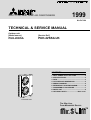
SPLIT-TYPE, HEAT PUMP AIR CONDITIONERS
No.OC184
TECHNICAL & SERVICE MANUAL
Outdoor unit
[Model names]
[Service Ref.]
PUH-4VKSA
PUH-4VKSA.UK
CONTENTS
1.
2.
3.
4.
5.
6.
7.
8.
9.
PART NAMES AND FUNCTIONS·····················2
SPECIFICATIONS ·············································2
DATA··································································3
OUTLINES AND DIMENSIONS ························4
WIRING DIAGRAM ···········································5
REFRIGERANT SYSTEM DIAGRAM··················6
DISASSEMBLY PROCEDURE ·························7
PARTS LIST ······················································9
OPTIONAL PARTS ··························Back cover
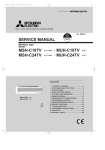
OUTDOOR UNIT
The Slim Line.
From Mitsubishi Electric.
1
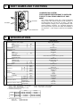
PART NAMES AND FUNCTIONS
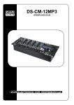
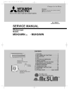
CHARGELESS SYSTEM
PRE-CHARGED REFRIGERANT IS SUPPLIED
FOR UP TO 30m PIPING LENGTH AT SHIPMENT.
The unique refrigerant circuit and a large accumulator
always control the optimal refrigerant level regardless of
the length (50m max. and 5m min.) of piping. The additional refrigerant charging work during installation often
causes problems. Therefore, it is completely eliminated.
This unique system improves the quality and reliability of
the work done. It also helps to speed up the installation
work.
Air outlet
Air intake
PUH-4VKSA.UK
OUTDOOR UNIT
2
SPECIFICATIONS
Service Ref.
Power supply (phase, cycle, voltage)
Input
Running current
Starting current
External finish
Refrigerant control
Compressor
Model
Motor output
Starter type
Protection devices
Cranckcase heater
Heat exchanger
Fan(drive) o No.
Fan motor output
Airflow
Defrost method
Noise level
REFRIGERANT
PIPING
kW
A
A
kW
kW
CMM
W
D
H
Dimensions
PUH-4VKSA.UK
Single, 50Hz, 220~240V
3.52
16.3
79
Munsell 5Y 7/1
Capillary tube
Hermetic
NH56VNDT
2.7
Line start
Internal thermostat, thermal switch, Hp switch
38
Plate fin coil
Propeller (direct) o2
0.065+0.065
95
Reverse cycle
54
870(34-1/4)
295+24 (11-5/8 add 1)
1258(49-1/4)
94(207)
R-22
4.2(9.2)
1600 (MS-32)
9.52 (3/8)
19.05(3/4)
Flared
Flared
Max. 50m
Max. 50m
Weight
Refrigerant
Charge
Oil (Model)
dB(A)
mm(in)
mm(in)
mm(in)
kg(lbs)
kg(lbs)
CC
mm(in)
mm(in)
Liquid
Gas
Indoor side
Connection method
Outdoor side
Height difference
Between the indoor & outdoor unit
Piping length
Pipe size O.D.
Notes1. Rating Conditions (JIS B8616)
Cooling : Indoor :27°C(80°F)DB. 19°C(66°F)WB
Heating : Indoor :20°C(68°F)DB.
Refigerant piping length (one way) :5m (16ft)
2. Guaranteed operating range
Cooling
Heating
Upper limit
Lower limit
Upper limit
Lower limit
Indoor
32°C DB, 23°C WB
21°C DB, 15°C WB
27°C DB
20°C DB
Outdoor :35°C(95°F)DB. 24°C(75°F)WB
Outdoor :7°C(45°F)DB. 6°C(43°F)WB
Outdoor
43°C DB
-5°C DB
24°C DB, 18°C WB
-5°C DB, -6°C WB
3. Above values are as follows.
Indoor Unit
1 phase 240V 50Hz
Outdoor Unit
1 phase 240V 50Hz
2
3
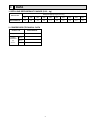
DATA
1. REFILLING REFRIGERANT CHARGE (R-22 : kg)
Refrigerant pipimg length (one way)
Service Ref.
PUH-4VKSA.UK
5m
10m
15m
20m
25m
30m
35m
40m
45m
50m
3.5
3.6
3.8
3.9
4.1
4.2
4.4
4.5
4.6
4.8
2. COMPRESSOR TECHNICAL DATA
Outdoor unit
PUH-4VKSA.UK
Compressor Model
NH56VNDT
Winding
Resistance
(')
at 20-C
U-V
(R-C)
U-W
(R-C)
W-V
0.64
1.55
—
3
Handle
for moving
95
10
Rear piping hole
For 10 units or less
138
Rear fresh
air intake
Side air intake
23
7
295(11-5/8)
Outlet guide
installation hole
Handle for moving
24(1)
Air intake
524
300
1000
33
Drain hole
40
524
870(34-1/4)
Air intake
500(19-11/16)
Drain hole
2-12o23 Oval holes
(standard bolt M10)
302
Air outlet
185
(7-9/32)
Refrigerant-pipe flared
connection [19.05 3/4F
Refrigerant-pipe flared
connection [9.52 3/8F
12
R6
65
500
Note:Allow adequate
upper clearance
120
60
Service space
Knock out holes for
power line 2-[27
Standard bolt length
Front right piping holesdetail figures
Knock out hole
for right piping
R2
(refrigerant,
0
drainage and wiring)
Knock out hole
for front piping
(refrigerant,drainage
and wiring)
Bottom
piping hole
39
10
10
Front opening
Terminal block for power line
and Ground terminal
Handle
for moving
60
10
Terminal block for
indoor and outdoor
unit connection
Service panel
2-U-shaped
notched
holes
104
185
(7-9/32)
382
150
585
345
61
524
83
17
39.5 27.5
330(13)
362(14-1/4)
15
403
52
1258(49-1/2)
The upper side must be open.
0
R2
959
57
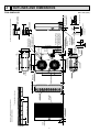
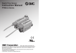
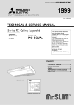
Outdoor Unit-Necessary surrounding clearance
80
45
Outdoor Unit-Necessary surrounding clearance
(Concentrated installation)
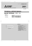
PUH-4VKSA·UK
17
500
300
100
25 max.
4
53
4
OUTLINES AND DIMENSIONS
Unit : mm (inch)
5
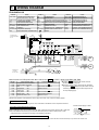
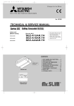
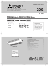
WIRING DIAGRAM
PUH-4VKSA·UK
SYMBOL
NAME
CN3<O.B> CONNECTOR(CONNECTING
WIRES INDOOR/OUTDOOR)
CN4T<O.B> CONNECTOR(TRANSFORMER)
HC
CRANKCASE HEATER
C1
FAN MOTOR CAPACITOR
C2
COMPRESSOR CAPACITOR
FC<O.B> FAN CONTROLLER
F<O.B>
FUSE(6A)
LD1-LD8<O.B> LED(CHECK,SERVICE)
26C
DISCHARGE PIPE THERMOSTAT
YLW
2
ORN
3
BRN
LED
TH
O.B
SW1
TB3
4 3 2 1
CN4
LD1
LD2
LD3
LD4
LD5
LD6
LD7
LD8
SW3
CN2
OFF
ON
21
3
2 CN3
1
X14 X13 X12 X11
X14
X13
X12
26C
X11
63H1
CN4T
4
YLW
ORN
RED
AC12.3V
240V
230V
220V
21R
52C
21
S4
CH
ZNR
R
WHT
WHT
21S4
GRY
GRY
BRN
BRN
AC
12.3V
TRF
BLU
BLU
RED
RED
SV
RED
RED
S
MF1
T
BLU BLU
A1
5
HC
52C
MF2
51CM
F
4 3 2 1
F.C
63H2
63H1
A2
7 6 X16 2
X16
T
26C
C1
GRY
GRY
WHT
WHT
1
X16
5
BLU
SW2
YLW
DC 12V
1
NAME
COMPRESSOR RELAY
SOLENOID COIL RELAY
SOLENOID COIL RELAY
HIGH PRESSURE RELAY
SURGE ABSORBER
4-WAY VALVE SOLENOID COIL
COMPRESSOR CONTACTOR
CONTROL HIGH PRESSURE SWITCH
PROTECT HIGH PRESSURE SWITCH
YLW
VLT
VLT
BLK
BLK
CONNECTING WIRES
SYMBOL
NAME
X12<O.B>
COMPRESSOR
X13<O.B>
FAN MOTOR
OUTDOOR CONTROLLER BOARD X14<O.B>
SOLENOID COIL(BYPASS VALVE) X16
SELECT SWITCH(CHECK,SERVICE) ZNR<O.B>
21S4
TRANSFORMER
52C
TERMINAL BLOCK
OUTDOOR COIL THERMISTOR 63H1
63H2
CRANKCASE HEATER RELAY
EARTH
BRN
BRN
TO INDOOR UNIT
SYMBOL
MC
MF
O.B
21R
SW1 • 2 • 3<O.B>
T
TB1,3
TH
X11<O.B>
8
~ (1PHASE)
C1
RED
L1/1
T1/2
RED
BLU
N
L3/5
220-240V 50Hz
GRN/YLW
WHT
BLU
RED
ORN
MF
63H2
BLU
TB1
L
3
4
2
1
GRY
RED
POWER SUPPLY
WHT
BLU
RED
ORN
C2
T3/6
52C
WHT
WHT
3
BLU
BLU
4
BRN
BRN
2
YLW
YLW
1
MF
BLK R
S
RED
MC
WHT C
Main functions of LED (when both No.1 and No.2 of SW3 are "OFF") How to use SW1 and SW2
LED No.
LD1
LD2
LD3
LD4
LD5
LD6
LD7
LD8
Output Display (light)
Compressor indoor command
Heating indoor command
63H1
ON
Compressor
ON
Outdoor fan
ON
4-way valve
ON
Bypass valve
ON
Crankcase heater ON
Check Display (flashing)
● Pressing SW1 erases the past check contents
stored on the microcomputer.
● The output display (light) remains during operation
Pipe sensor short/open
63H2 functions
but pressing SW2 displays the past check contents
in flashing mode. Pressing the switch again returns
to output display(light).
26C Overheat protection
TH overheat protection
Defective input
NOTE: If the operation of the protection device stops to function, then check the display flashes.
CAUTION FOR SERVICING
● Connect the lead wires according to the colour indication of the sticker on the compressor terminal.
w When Power Supply is 220V
CAUTIONS FOR POWER SUPPLY WIRING
● Since LD8 lights when normal power is turned "ON", check the power supply with the ON or OFF LD8.
w Since the outdoor transformer (T) is connected with 240V power, if 220V or 230V power is used,
change the wiring connections according to the following procedure.
YELLOW 240V
ORANGE 230V
RED
220V
WHITE
CAUTION FOR INDOOR AND OUTDOOR CONNECTING WIRES
● Since the indoor and outdoor connecting wires have polarity,make sure to connect the same terminal numbers(1,2,3)for indoor and outdoor units.
5
6
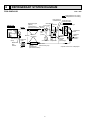
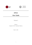
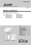
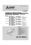
REFRIGERANT SYSTEM DIAGRAM
Unit : mm
PUH-4VKSA·UK
Refrigerant flow in cooling
Refrigerant flow in heating
High pressure
Control switch
Oil separator
Refrigerant pipe
Service
(option)
4-way valve
port
19.05A({3/4")
Ball valve
(with heat insulator) Strainer
Indoor unit
Flexible tube
Indoor
heat
exchanger
Strainer Flared
connection
Thermistor
(TH2)
Distributor
with
strainer
Restrictor
valve
Capillary
tube
Protective high
pressure switch
Outdoor unit
Outdoor heat exchanger
Thermistor
TH3
Service
port
(check)
Accumulator Compressor
Refrigerant pipe Ball valve
(with service port)
(option)
9.52A({3/8")
(with heat insulator)
6
Bypass
valve
Thermal
switch
(Discharge)
Restrictor
valve
Capillary
tube W1
Strainer
W1(O.D.3.2OI.D.2.0-R820)O2pcs
7
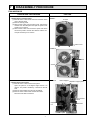
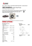
DISASSEMBLY PROCEDURE
PUH-4VKSA·UK
OPERATING PROCEDURE
PHOTOS
1. Removing the electrical parts
(1) Remove the 3 screws at the front and 2 screws at the
rear of the top panel.
(2) Remove the top panel.
(3) Remove the screw from the panel cover. Unhook the
catches from the side panel and pull the panel cover
toward you to remove.
(4) Remove the screw from the service panel. Pull down
the service panel to unhook the catches. Pull the service panel toward you to remove.
Photo 1
Screws
Panel cover
Photo 2
Terminal block
Screws
Photo 3
2. Removing the fan motors
(1) Remove the 3 screws and the front panel.
Open the panel to a 45-degree angle and lift it to
remove. The panel is hooked by 3 catches on the left
side.
(2) Remove the propeller nuts and the propellers.
(3) Remove the 3 screws each and the fan motors.
Disconnect the lead connectors.
Motor support Separator support plate
High pressure
switch
Propeller
nut
Valve bed
Propeller
7
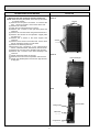
OPERATING PROCEDURE
PHOTOS
3. Removing the heat exchanger and the compressor
NOTE :When removing the panels, move them up and down
to unhook catches.
(1) Remove the rear panel set screws : 2 screws at the
front, 1 screw on the side, and 3 screws at the rear.
(2) Remove the valve bed.
(3) Open the rear panel rearward to remove.
(4) Remove the 4 screws of the right side panel and
remove it.
(5) Remove the 3 screws of the rear guard and remove it.
(6) Remove the 4screws of the separator support plate
and remove it.
(7) Remove the 2 screws of the motor support and
remove it.
(8) Remove the 5 screws of the valve bed. Lift the valve
bed to unhook the catches on both sides.
(9) Remove the electrical parts box.
(10) Disconnect the connectors of the high-pressure
switch, crankcase heater, shell thermo, and fan motor.
(11) Remove the 2 screws of the separator and remove it.
(12) Remove the 2 screws of the heat exchanger and
remove it.
(13) Detach the brazed points of the pipe.
(14) Remove the 3 nuts of the compressor and remove it.
(15) Detach the welded points of the suction pipe and discharge pipe.
Photo 4
Screws
Screws
Photo 5
Heat exchanger
Photo 6
Charge plug
Ball valve
Compressor
8
Accumulator
8
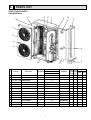
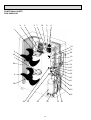
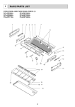
PARTS LIST
STRUCTURAL PARTS
PUH-4VKSA·UK
10 13
12
6
1
9
14
7
3
2
4
3
4
8
11
5
Q'ty/set
No.
Part No.
Part name
Specification
PUH-4
Remarks
VKSA.UK
1 S70 020 641 TOP PANEL
1
2 S70 004 668 FRONT PANEL
1
3 S70 001 675 FAN GUARD
2
4 S70 A00 655 PANEL HANDLE
3
5 S70 004 661 SERVICE PANEL
1
6 S70 040 662 SIDE PANEL
1
7 S70 040 682 REAR PANEL
1
8 S70 020 658 PANEL COVER
1
9 S70 040 698 REAR GUARD
1
10 S70 050 130 MOTOR SUPPORT
1
11 S70 001 686 BASE
1
–
F.ST SCREW
13
(Z004M203H10)
13
–
MOTOR PLATE
1
(BG00G231G01)
14
–
LABEL(MITSUBISHI)
1
(BC79G510H01)
12
9
Price
Wiring RecomDiagram mended
Unit Amount
Symbol Q'ty
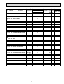
FUNCTIONAL PARTS
PUH-4VKSA·UK
6
5
3 7
32
9
8
1
23
2
33
24
30
1
18
13
29
31
17
15
34
2
27
11
30
14
10
22
28
19
25
26
10
21 20
Part numbers that are circled are not shown in the figure.
Q'ty/set
No.
Part No.
Part name
Specification
PUH-4
VKSA.UK
1 S70 040 763 FAN MOTOR
2
PN6V60-UA
2 S70 001 115 PROPELLER
2
3 S70 A04 315 OUTDOOR CONTROLLER BOARD
1
4 S70 A01 529 D.P ASSY
1
Price
Wiring RecomRemarks Diagram mended
Unit Amount
Symbol Q'ty
MF
O.B
5 S70 509 716 TERMINAL BLOCK
3P(L,N,;)
1
TB1
6 S70 516 716 TERMINAL BLOCK
3P(1,2,3)
1
TB3
7 S70 106 799 TRANSFORMER
1
T
8 S70 39J 255 FAN MOTOR CAPACITOR
2
C1
9 S70 956 708 COMPRESSOR CONTACTOR S-N35
1
52C
10 S70 272 428 SOLENOID VALVE
1
11 S70 106 242 SOLENOID COIL
1
12 S70 A00 425 CAPILLARY TUBE
4+ 440V
{3.2O{2.0O820mm
21R
2
13 S70 993 418 RESTRICTOR VALVE
2
14 S70 42L 450 STRAINER
1
15 S70 260 403 4-WAY VALVE
1
16 S70 A02 201 DISCHARGE PIPE THERMOSTAT
1
17 S70 A11 450 STRAINER
1
18 S70 943 413 CHARGE PLUG
1
19 S70 A01 413 CHARGE PLUG
1
20 S70 670 411 BALL VALVE
3/4"
1
21 S70 943 410 BALL VALVE
3/8"
1
26C
22 S70 A14 490 OIL SEPARATOR
1
23 S70 A12 440 ACCUMULATOR
1
24 S70 A00 202 OUTDOOR COIL THERMISTOR
1
TH
1
MC
1
HC
1
63H1
1
63H2
25 S70 610 300 COMPRESSOR
NH-56VNDT
26 S70 A02 236 CRANKCASE HEATER 240V 38W
27 S70 A00 208 CONTROL HIGH PRESSURE SWITCH
28 S70 A04 208 PROTECT HIGH PRESSURE SWITCH
OFF
ON
2.55MPa 2.1MPa
OFF
ON
3.3MPa 2.1MPa
2
29 S70 012 408 OUTDOOR HEAT EXCHANGER
30 S70 30L 097 NUT
M8
2
31 S07 113 425 CAPILLARY TUBE
{2.5O{0.6O1000A
1
32 S70 737 215 HIGH PRESSURE RELAY LY-2F 230V 10A
1
X16
33 S70 040 723 COMPRESSOR CAPACITOR 60+ 450V
1
C2
34 S70 A00 242 4WAY COIL
1
11
9
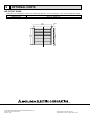
OPTIONAL PARTS
AIR OUTLET GUIDE
This guide is for changing the outdoor unit air discharge direction. For PUH-4/5/6 type, 2 sets of PAC-292SG are needed.
Part No.
PAC-292SG (1 pc/set)
Applied Service
PUH-1.6~6K(S)A type
538
7
524
4 holes
7 {6
524
7
537
7
72
HEAD OFFICE MITSUBISHI DENKI BLDG.MARUNOUCHI TOKYO100-8310 TELEX J24532 CABLE MELCO TOKYO
© Copyright 1999 MITSUBISHI ELECTRIC ENGINEERING CO.,LTD.
Issued in Mar.1999 No.OC184 242
Printed in Japan.
New publication, effective Mar.1999
Specifications subject to change without notice.