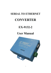
1
LanConn-100 User Guide
User’s Manual
First Edition
(C)2002-2003 Eletech Enterprise Co., Ltd.
All Rights Reserved.
1. Description
LanConn-100 is a full duplex serial port to Ethernet converter. Through LanConn-100, your system
can easily communicate with the LAN, WAN or Internet via the RS232/RS422/RS485 port. When
sending data to the network, LanConn-100 automatically adds the necessary TCP/IP stack. When
receiving data from the network, LanConn-100 automatically removes the TCP/IP stack.
LanConn-100 also provides a device interface with seven digital I/O ports, making it a powerful and
cost effective solution to many applications such as industrial automation and remote (Internet
enabled) device control.
2. System Structure
3. Specifications
Hardware
Winbond 78E58 CPU, 36.864 MHz
32KB SRAM
Realtek 8019AS Ethernet controller
Protocol
ARP, IP, UDP, TCP, ICMP, HTTP, DHCP
Interface
10 Mbps Ethernet interface
300-115200 bps asynchronous stream
(RS232/RS422/RS485)
Throughput
9 KB/s half-duplex,
6 KB/s full-duplex
LanConn-100 User’s Guide
1
4. Hardware Connection Diagram
POWER DC9V
IO1
1
IO2
2
IO3
3
IO4
4
IO5
5
IO6
6
IO7
7
DCD
DSR
RS-232
RXD
RTS
TXD
CTS
DTR
GND
WRESET 9
GND 10
Tx+
Tx Rx+
Rx-
1
2
3
4
5
6
7
8
LanConn-100 User’s Guide
rsRxrsRx+
RJ45
RS-485
rsTxrsTx+
2
5. Etm Manager Program
Etm.exe is a device manager program which runs under the Windows 32 bit environment. Using
UDP broadcast packets, Etm.exe allows you to inquire and modify LanConn-100’s basic parameters.
Upon executing Etm.exe, the following screen (example) will appear if a LANCON-100 is found.
The screen shows number of devices detected, as well as their IP Address, Subnet Mask, MAC
Address and Device ID. If you select the [View] / [Refresh] function (or press the F5 key), the system
will re-detect the devices and update the screen accordingly. Because Etm.exe uses UDP
Broadcast Packets, it has the following characteristics:
It’s not subject to the subnet restriction – the program is usable even if LanConn-100’s IP and
the PC’s IP are not on the same subnet.
Since broadcast packets cannot pass through the router, only the devices on the same network
section can be detected.
Due to the fact that Etm.exe uses UDP broadcast, for security reasons the Configuration is available
when only one LanConn-100 device is detected. In this case, the following parameters can be
modified under the Configuration.
LanConn-100 User’s Guide
3
IP Address
Enter the new IP
address and click [OK]. Or click [Cancel] to abort the operation
Subnet Mask
Enter the Subnet Mask value and click [OK]. Or click [Cancel] to abort the operation
LanConn-100 User’s Guide
4
6. Browser Configuration
LanConn-100 supports the HTTP communication protocol. All device configurations can be easily
set in the browser program. Just type in the LanConn-100’s IP address, and the following screen will
be displayed.
The following basic information is shown in the display.
• System time elapsed: The elapsed time since the system was turned on. In the screen
shown above, the elapsed time is 0 hour 0 minute and 9 seconds. This information can be used to
determine if the device has been operating normally without being reset.
• Firmware release date: This is used to identity the firmware version of the LanConn-100
device.
• Ethernet address: The Ethernet address has 6 hex-decimal bytes.
Now, type in the password and click the [Login] button to enter the configuration screen. Note that
initially the password is not required, just click the [Login] button.
LanConn-100 User’s Guide
5
• If the correct password is not entered in three tries, you have to wait at least 20 minutes to try
again.
The following is an example of the configuration screen.
Click the [Update] button to update the parameters.
IP Address
4 numbers separated by dots, assigned by the server under DHCP mode.
Subnet mask
4 numbers separated by dots, assigned by the server under DHCP mode.
Gateway address
4 numbers separated by dots, assigned by the server under DHCP mode.
DHCP client
If disabled, then IP address, Subnet masks and Gateway address must be
assigned manually.
Socket port of
If disabled, then IP address, Subnet masks and Gateway address must be
HTTP setup
assigned manually.
Socket port of
LanConn-100 User’s Guide
• Port Number: any number between 1 and 65536, can be assigned to port
6
serial I/O
80 and 81. this function allows users build their own Web pages.
• Socket Type
TCP Server, uses TCP protocol, passively waits for Client.
TCP Client, uses TCP protocol, actively connects to Server.
UDP Client, uses UDP protocol, exchanges packets with Server without
connection.
This is an extra I/O socket with similar configuration as the socket port of serial
I/O, but the Port Number must be different.
• Port Number: any number between 1 and 65536, except 80 and 81 (which
Socket port of
digital I/O
have been designated as the web pages.)
• Socket Type:
TCP Server, uses TCP protocol, passively waits for Client.
TCP Client, uses TCP protocol, actively connects to Server.
UDP Client, uses UDP protocol, exchanges packets with Server without
connection.
Client mode
server IP address
Client mode
server socket port
The server IP address under TCP Client or UDP Client mode.
Any Valid port can be assigned (1-65535),
• Baud Rate: 300 - 115200 bps
•
N,8,1 (10 bits)
N,8,2 (11 bits)
Serial I/O settings
E,7,1 (10 bits)
(baud rate, parity,
E,7,2 (11 bits)
data bits, stop bits)
O,7,1 (10 bits)
O,7,2 (11 bits)
E,8,1 (11 bits)
O,8,1 (11 bits)
• RS232: use only TxD and RxD to transfer and receive data.
• RS232 (RTS/CTS):
TxD, RxD – transfer and receive data.
Interface of serial
I/O
RTS/CTS – flow control.
• RS232 (RTS/CTS, DTR/DSR):
TxD, RxD – transfer and receive data.
RTS/CTS – flow control.
DTR – socket connection status, DSR – socket connection control.
LanConn-100 User’s Guide
7
• RS485 (Half duplex): half duplex.
• RS422 (Full duplex): full duplex.
If packet mode is disabled, the data received from the serial port will be
Packet mode of
transmitted immediately with minimal delay. If packet mode is enabled, the data
serial input
will be saved in the buffer memory first, and transmitted when the entire packet is
received or when the buffer memory is full.
Packet mode
inter-packet
timeout
Device ID
In packet mode, the time constant used to determine if the packet is finished.
Acceptable range is 10 to 1000 ms.
User assigned device ID number. Acceptable range is 0 to 65535.
If this function is enabled, the device will report the device ID after the socket is
connected. The format is:
Report device ID
Serial I/O socket
nnnnnA[LF][CR]
when connected
Digital I/O socket
nnnnnB[LF][CR]
There are eight bytes: “nnnnn” is the 5-digit device ID, [LF] is decimal 10, and
[CR] is decimal 13.
Setup password
The login password can be empty of 1 to 15 characters long. If the password is
empty then no password is required for login.
This is the password for socket connection. It can be empty or 1 to 15 characters
long. If the password is empty, then no password is required for socket
connection. If the password is not empty, then it must be entered immediately
Access password
after socket connection is made. If the password is not entered within 10
seconds or a wrong password is entered, then LanConn-100 will automatically
disconnect. If a wrong password is entered for three times in a roll, no connection
is allowed within 20 minutes.
LanConn-100 User’s Guide
8
After clicking on the [Update] button, the following screen will appear:
At this point LanConn-100 is restarting with the new parameters. In about 5 seconds the system will
return to the Login screen.
LanConn-100 User’s Guide
9
7. Testing
A. Null Modem
(1) Make a null modem by connecting pin 2 and 3 together on a 9-pin male RS-232 connector. Plug
the null modem on LanConn-100’s RS-232 connector.
(2) Connect LanConn-100 onto the LAN, into the same subnet as the testing PC.
(3) Execute Hypertrm.exe. The following screen will appear.
(4) Key in your favorite name and click the [OK] button. The following screen will appear.
IP Address
Socket port
of serial I/O
LanConn-100 User’s Guide
10
(5) Enter IP address and socket port of serial I/O. Make sure TCP/IP (Winsock) is selected and click
the [OK] button. The following screen will appear.
Characters looped back from
the serial port
.
(6) At this point you may type in a few test characters. These characters will be looped back through
the null modem, and displayed on the screen. Note that “Rx” will flash once whenever you type
in a character, to indicate the receiving of that character. You may also send a text file and it will
be displayed on the screen. However, you should not use the “Send File” function because the
transmission protocols such as Zmodem will cause Hyperterminal to reset LanConn-100.
B. Digital I/O
(1) Connect LanConn-100 onto the LAN, into the same subnet as the testing PC.
(2) Execute Hypertrm.exe. The following screen will appear.
LanConn-100 User’s Guide
11
(3) Key in your favorite name and click the [OK] button. The following screen will appear.
IP Address
Socket port
of digital I/O
(4) Enter IP address and socket port of digital I/O. Make sure “TCP/IP (Winsock)” is selected and
click the [OK] button. The following screen will appear.
Current status of
digital I/O ports
LanConn-100 User’s Guide
12
(5) Select [File]\[Property]\[Configure]\[ASCII] and make the following settings.
(6) At this point you may key in command strings to change the digital I/O port status. For example,
020 == change output #2 to low
021 == change output #2 to high
070 == change output #7 to low
071 == change output #7 to high
Change output #2 to low
Change output #2 to high
Change output #7 to low
Change output #7 to high
LanConn100 reports
digital I/O status
LanConn-100 User’s Guide
13