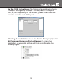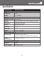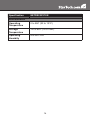
1
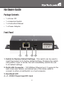
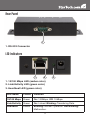
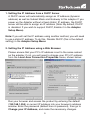
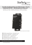
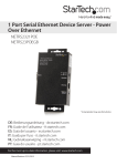
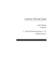
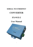
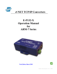
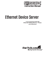
NETRS2321POE
Instruction Manual
Ethernet Device Server
1-Port Industrial RS-232
Ethernet Device Server - Power
over Ethernet FCC Compliance Statement
This equipment has been tested and found to comply with the limits for a Class B digital
device, pursuant to part 15 of the FCC Rules. These limits are designed to provide reasonable protection against harmful interference in a residential installation. This equipment generates, uses and can radiate radio frequency energy and, if not installed and
used in accordance with the instructions, may cause harmful interference to radio communications. However, there is no guarantee that interference will not occur in a particular installation. If this equipment does cause harmful interference to radio or television
reception, which can be determined by turning the equipment off and on, the user is
encouraged to try to correct the interference by one or more of the following measures:
• Reorient or relocate the receiving antenna.
• Increase the separation between the equipment and receiver.
• Connect the equipment into an outlet on a circuit different from that to which the receiver
is connected.
• Consult the dealer or an experienced radio/TV technician for help.
Use of Trademarks, Registered Trademarks, and other Protected Names and Symbols
This manual may make reference to trademarks, registered trademarks, and other
protected names and/or symbols of third-party companies not related in any way to
StarTech.com. Where they occur these references are for illustrative purposes only and
do not represent an endorsement of a product or service by StarTech.com, or an endorsement of the product(s) to which this manual applies by the third-party company in
question. Regardless of any direct acknowledgement elsewhere in the body of this document, StarTech.com hereby acknowledges that all trademarks, registered trademarks,
service marks, and other protected names and/or symbols contained in this manual and
related documents are the property of their respective holders.
Table of Contents
Hardware Guide................................................................ 2
Package Contents........................................................................2
Front Panel...................................................................................2
Rear Panel....................................................................................3
LED Indicators..............................................................................3
Hardware installation....................................................... 4
Configuring the Adapter.................................................. 4
Setting the IP Address..................................................................4
Setting the IP Address from a DHCP Server............................5
Setting the IP Address using a Web Browser...........................5
Setting the IP Address using the Em.exe Utility.......................6
Managing the Adapter Settings....................................................6
Controller Setup Menu Items........................................................7
Software Installation........................................................ 9
VSP Virtual COM Port Driver........................................................9
Installing the VSP Virtual COM Port Driver...................................10
Specifications................................................................... 13
Technical Support............................................................ 15
Warranty Information....................................................... 15
i
Hardware Guide
Package Contents
• 1 x Driver CD
• 1 x Industrial Switch
• 1 x Instruction Manual
• 1 x Power Adapter
Front Panel
1
2
3
4
1. Switch to Restore Default Settings - This switch can be used to reset the product to its factory default settings. Pressing the switch using either a pen or similar tool will immediately restore the unit to its default settings.
2. RJ45 LAN Connector - 10/100Mbps Ethernet port. It supports the auto cross-over feature, and allows use of the same cable to
connect to either a Hub/Switch or a host computer.
3. Heartbeat LED
4. +7~12VDC Power Input DC Jack
2
Rear Panel
1
1. RS-232 Connector
LED Indicators
1
2
3
1. 10/100 Mbps LED (amber color)
2. Link/Activity LED (green color)
3. Heartbeat LED (green color)
LED Name
Colour
Function
10/100 Mbps
Green
On: 100Mbps. Off: 10Mbps.
Link/Activity
Green
On: Linked. Blinking: Transfering Data.
Heartbeat
Amber
Blinking: Normal Operation. Not Blinking:
Malfunction.
3
Hardware installation
1. Use static electricity discharge precautions. Remove possible static
discharge potential from any objects that the adapter may come in contact with prior to installation. This can be accomplished by
touching a bare metal chassis rail after you have turned off the power.
2. If you will be externally powering the device, connect the DC power adapter. If connecting to a PoE switch, hub, or other device, then
a power adapter is not required, as the product will draw its power from the host device it is connected to. In this case, ensure that your switching hub is the PoE type that can act as PSE (Power Source Equipment).
3. Connecting LAN cable: Use a standard straight-through Ethernet cable to connect to a Hub or Switch. If you connect the adapter to your computer’s Ethernet port instead, you don’t need to change to a cross-over type cable since the adapter provides the auto cross- over feature.
4. Connect the Adapter’s serial port to your serial device.
5. Use the DIN RAIL mounting Kit if you want to place the product on the industrial DIN RAIL. (optional)
Configuring the Adapter
Setting the IP Address
Please consult your Network Administrator to determine the appropriate IP address. The adapter comes with the factory installed IP address
192.168.1.254. It is ready to accept a new IP address from a DHCP
Server. If your network has a DHCP server, it will automatically assign
an IP address to the Adapter the first time it is connected and powered
up.
4
1. Setting the IP Address from a DHCP Server
A DHCP server will automatically assign an IP address (dynamic address) as well as Subnet Mask and Gateway to this adapter. If you power up the Adapter without a fixed (static) IP address, the DHCP server will be able to assign an IP address (Note: By default, DHCP is disabled. If you wish to support DHCP, Enable it in the Adapter Setup Menu).
Note: If you will set the IP address using another method, you will need
to use a static IP address. To do this, Disable DHCP (this is the default
setting) in the Adapter Setup Menu.
2. Setting the IP Address using a Web Browser
Please ensure that your PC’s IP address is set to the same subnet as the adapter. If not, you will need to change your PC’s IP address from the Local Area Connection Properties menu, shown below:
Run your browser and access the product by entering the default (192.168.1.254) or current IP address into your browser’s address window. Enter the password (default has no password), then go to Change your IP Address, and make the necessary changes.
5
3. Setting the IP Address using the Em.exe Utility
The Em.exe is a Microsoft Windows based utility used to identify the adapters connected on the same subnet and network segment. To
run the Em.exe utility, please insert the driver CD supplied with the Adapter. Open the program at the following location (assume the
CD-ROM drive is at E):
E:\IO_over_IP\Utilities\Em\Em.exe
Managing the Adapter Settings
When you enter the Adapter Setup Menu, the following page will be
available for your access. By default there is no password for entry.
Once you have entered the Controller Setup Menu and made the
necessary changes, click the Update button. Also ensure that you
make note of your password as you will need it to enter the setup menu
again.
6
Controller Setup Menu Items
Menu Item
Description
IP Address
4 numbers separated by dots. If enabled, these
can be assigned by the DHCP server.
Subnet Mask
4 numbers separated by dots. If enabled, these
can be assigned by the DHCP server.
Gateway Address
4 numbers separated by dots. If enabled, these
can be assigned by the DHCP server.
DHCP Client
If disabled, the IP address, Subnet mask and
Gateway address must be assigned manually.
7
Menu Item
Description
Socket Port of HTTP
Setup
If disabled, the IP address, Subnet mask and
Gateway address must be assigned manually.
Socket Port of Serial
I/O
Port Number:
Any number between 1 and 65536,except 80
and 8080 (these have been designated as the
web pages).
Socket Type:
TCP Server - Uses TCP protocol, passively
waits for Client.
TCP Client - Uses TCP protocol, actively
connects to Server.
UDP Client - Uses UDP protocol, exchanges
packets with Server without connection.
Socket Port of Digital
I/O
Spared function for the future expansion.
Currently has no function.
Destination IP
Address/Socket Port
(TCP client and UDP)
The Server IP address under TCP client or
UDP client mode.
Serial I/O Settings
(baud rate, parity,
data bits, stop bits)
Baud Rate: 300 – 115200 bps
Parity Bits: No Parity, Even, Odd
Data Bits: 5, 6, 7, 8
Stop Bit: 1 or 2
Interface of serial I/O
RS-232
Packet mode of serial
input
If packet mode is disabled, the data received
from the serial port will be transmitted
immediately with minimal delay. If packet mode
is enabled, the data will be saved in the buffer
memory first, and transmitted when the entire
packet is received or when the buffer memory
is full.
8
Menu Item
Description
Packet mode interpacket timeout
In packet mode, the time constant used to
determine if the packet is finished. Acceptable
range is 10 to 1000 ms.
Device ID
User assigned device ID number. Acceptable
range is 0 to 65535.
Report device ID
when connected
If this function is enabled, the device will report
the device ID after the socket is connected. The
format is:
Serial I/O socket
nnnnnA[LF][CR]
Digital I/O socket nnnnnB[LF][CR]
There are eight bytes: nnnnn is the 5-digit
device ID, [LF] is decimal 10, and [CR] is
decimal 13
Setup password
The login password can be empty or 1 to 15
characters long. If the password is empty then
no password is required for login.
Software Installation
VSP Virtual COM Port Driver
The VSP is a redirector driver that allows your applications to use
serial devices provided by serial device servers on your network. This
redirection is achieved by creating one or more virtual COM port(s) that
allow these networked serial devices to function as though they are
directly connected to the local computer.
Since the redirector’s virtual COM port(s) function much like standard
Windows COM ports, your application software sees no difference
between a local serial device and one provided by a serial server.
9
Installing the VSP Virtual COM Port Driver
1. Locate the necessary Software in the following folder on your driver CD. The VSP COM.exe is the redirector software. The Em.exe is used to setup the hardware mode to support VSP redirector.
2. Configure your hardware mode to support VSP.
• Run the EM.exe application to find the device hardware.
• Enter the setup menu by double clicking the listed hardware.
• Click Login (by default settings, there is no password).
10
• Change the settings to COM Port, save the changes, and exit the setup menu.
3. Run the VSP Setup Program.
•
Double click the VSP COM.exe application in the VSP folder
on the supplied CD. You may receive a message indicating that this driver has not yet passed Windows logo testing. If so, click Continue Anyway.
• Select the COM ports to be redirected by checking the boxes next to them:
11
•
Set the COM Port settings: The following figure shows only one COM port setting being changed. You may have 4 COM ports (or 1, 2 ports depending on the model), you will need to set it 4 times for, once for each COM port.
•
Checking the Installation: Go to the Device Manager (right click My Computer, Hardware, Device Manager) to check the
installation, a successful settings will look something like the
following figure:
12
Specifications
Specification
NETRS2321POE
LAN
Connector
RJ45
Speed
10/100Mbps
RS-232
Number of Ports
1 x RS-232
Signals
TXD, RXD, RTS, CTS, DTR, DSR, DCD, GND
Connector
DB9 Male (RS-232)
Parity
None, Odd, Even
Data Bits
6, 7, 8
Stop Bits
1, 2
Speed
300 to 115.2Kbps
Power Requirements
Power Input
12V DC (via DC Jack), or
48V DC (via Ethernet Cable, PoE model only)
Power
Consumption
110mA @ 12V DC
Mechanical Specifications
Material
Metal
Gross Weight
250.5g (0.55 lb)
13
Specification
NETRS2321POE
Environmental
Operating
Temperature
0 to 55C (32 to 131F)
Storage
Temperature
-20 to 85C (-4 to 185F)
Operating
Humidity
5 to 95% RH
14
Technical Support
StarTech.com’s lifetime technical support is an integral part of our commit-ment to provide industry-leading solutions. If you ever need help
with your product, visit www.startech.com/support and access our comprehensive selection of online tools, documentation, and downloads.
Warranty Information
This product is backed by a one year warranty.
In addition, StarTech.com warrants its products against defects in
materials and workmanship for the periods noted, following the initial
date of purchase. During this period, the products may be returned for
repair, or replacement with equivalent products at our discretion. The
warranty covers parts and labor costs only. StarTech.com does not warrant its products from defects or damages arising from misuse, abuse,
alteration, or normal wear and tear.
Limitation of Liability
In no event shall the liability of StarTech.com Ltd. and StarTech.com
USA LLP (or their officers, directors, employees or agents) for any damages (whether direct or indirect, special, punitive, incidental, consequential, or otherwise), loss of profits, loss of business, or any pecuniary loss,
arising out of or related to the use of the product exceed the actual price
paid for the product. Some states do not allow the exclusion or limitation
of incidental or consequential damages. If such laws apply, the limitations or exclusions contained in this statement may not apply to you.
15
StarTech.com has been making “hard-to-find easy” since 1985,
providing high quality solutions to a diverse IT and A/V customer
base that spans many channels, including government, education
and industrial facilities to name just a few. We offer an unmatched
selection of computer parts, cables, A/V products, KVM and Server Management solutions, serving a worldwide market through our
locations in the United States, Canada, the United Kingdom and
Taiwan.
Visit www.startech.com today for complete information about all
our products and to access exclusive interactive tools such as the
Cable Finder, Parts Finder and the KVM Reference Guide.