1
Witte Software
Modbus Poll User manual
Modbus Master Simulator
June 2015
Modbus Poll version 6.3
Copyright: Witte Software, 2002 -2015
http://www.modbustools.com
Table of content
1
2
3
4
5
6
Modbus Poll ............................................................................................................................................... 5
Modbus Poll Features ................................................................................................................................ 6
2.1
Connections ....................................................................................................................................... 6
2.2
Supported Modbus Functions ........................................................................................................... 6
2.3
Data logging ....................................................................................................................................... 6
2.4
Display formats .................................................................................................................................. 6
2.5
Miscellaneous features...................................................................................................................... 6
Overview .................................................................................................................................................... 7
3.1
Help from anywhere .......................................................................................................................... 7
3.2
Alias cells ........................................................................................................................................... 7
3.3
Value cells .......................................................................................................................................... 8
3.4
Change color and font ....................................................................................................................... 8
3.5
Open a new window .......................................................................................................................... 9
Connection dialog .................................................................................................................................... 10
4.1
Connection....................................................................................................................................... 10
4.2
Serial Settings .................................................................................................................................. 11
4.3
Mode ............................................................................................................................................... 11
4.4
Response timeout............................................................................................................................ 11
4.5
Min delay between polls ................................................................................................................. 11
4.6
Remote Server ................................................................................................................................. 11
4.7
Advanced settings............................................................................................................................ 11
4.7.1
RTS Toggle................................................................................................................................ 11
4.7.2
DSR........................................................................................................................................... 11
4.7.3
CTS ........................................................................................................................................... 12
4.7.4
DTR........................................................................................................................................... 12
4.7.5
Remove Echo ........................................................................................................................... 12
Read/Write definition.............................................................................................................................. 13
5.1
Slave ID ............................................................................................................................................ 13
5.2
Function code .................................................................................................................................. 13
5.2.1
Read functions ......................................................................................................................... 13
5.2.2
Write functions ........................................................................................................................ 14
5.3
Address ............................................................................................................................................ 14
5.3.1
Protocol/message address ...................................................................................................... 14
5.3.2
Device address ......................................................................................................................... 14
5.3.3
5 digits vs. 6 digits addressing ................................................................................................. 14
5.4
Address examples ............................................................................................................................ 14
5.4.1
Read Holding Registers ............................................................................................................ 14
5.4.2
Read Discrete Inputs................................................................................................................ 15
5.5
Scan rate .......................................................................................................................................... 15
5.6
Read/Write Disabled ....................................................................................................................... 15
5.6.1
Disable on error ....................................................................................................................... 15
5.7
Hide alias columns ........................................................................................................................... 15
5.8
Address in cell .................................................................................................................................. 15
5.9
PLC Addresses (Base 1) .................................................................................................................... 16
5.10 Enron/Daniel Mode ......................................................................................................................... 16
5.11 Rows ................................................................................................................................................ 16
Display formats ........................................................................................................................................ 17
6.1
Native Modbus registers ................................................................................................................. 17
6.2
32 bit long ........................................................................................................................................ 17
6.3
32 bit floating .................................................................................................................................. 17
6.4
64 bit double.................................................................................................................................... 17
http://www.modbustools.com
2
Modbus Poll User manual
7
8
Save/Open Workspace ............................................................................................................................ 18
Test center ............................................................................................................................................... 19
8.1
ASCII Example .................................................................................................................................. 19
8.2
TCP/IP Example................................................................................................................................ 19
8.3
Test center string file ....................................................................................................................... 19
8.3.1
Content of a string list ............................................................................................................. 19
8.4
Copy ................................................................................................................................................. 19
9 Modbus Data logging............................................................................................................................... 20
9.1
Text file ............................................................................................................................................ 20
9.1.1
Log Rate ................................................................................................................................... 20
9.1.2
Delimiters ................................................................................................................................ 20
9.1.3
Log if data changed only .......................................................................................................... 20
9.1.4
Log Errors ................................................................................................................................. 20
9.1.5
Log Date ................................................................................................................................... 21
9.1.6
Start Log when ok is pressed ................................................................................................... 21
9.1.7
Start Log when *mbp is opened .............................................................................................. 21
9.1.8
Flush to file immediately ......................................................................................................... 21
9.1.9
Append .................................................................................................................................... 21
9.2
Microsoft Excel ................................................................................................................................ 22
9.2.1
Log Rate ................................................................................................................................... 22
9.2.2
Header information ................................................................................................................. 22
10 Communication traffic ............................................................................................................................. 24
11 OLE/Automation ...................................................................................................................................... 25
11.1 Excel example .................................................................................................................................. 25
11.1.1 Excel 2007 ................................................................................................................................ 25
11.1.2 Excel 2010 ................................................................................................................................ 25
11.1.3 Excel sample code.................................................................................................................... 26
11.2 Connection Functions/Properties.................................................................................................... 27
11.2.1 Connection............................................................................................................................... 27
11.2.2 BaudRate ................................................................................................................................. 27
11.2.3 DataBits.................................................................................................................................... 27
11.2.4 Parity ........................................................................................................................................ 28
11.2.5 StopBits .................................................................................................................................... 28
11.2.6 SerialPort ................................................................................................................................. 28
11.2.7 ResponseTimeout .................................................................................................................... 28
11.2.8 ServerPort ................................................................................................................................ 28
11.2.9 ConnectTimeout ...................................................................................................................... 29
11.2.10
IPVersion .............................................................................................................................. 29
11.2.11
OpenConnection .................................................................................................................. 29
11.2.12
CloseConnection .................................................................................................................. 30
11.3 Read Functions ................................................................................................................................ 31
11.3.1 ReadCoils ................................................................................................................................. 31
11.3.2 ReadDiscreteInputs ................................................................................................................. 31
11.3.3 HoldingRegisters ...................................................................................................................... 31
11.3.4 InputRegisters .......................................................................................................................... 32
11.3.5 ShowWindow........................................................................................................................... 32
11.3.6 Byte order ................................................................................................................................ 32
11.3.7 ReadResult ............................................................................................................................... 33
11.3.8 WriteResult .............................................................................................................................. 33
11.4 Automation data properties ............................................................................................................ 34
11.4.1 Coil ........................................................................................................................................... 34
11.4.2 Signed Register ........................................................................................................................ 34
http://www.modbustools.com
3
Modbus Poll User manual
11.4.3 Unsigned Register .................................................................................................................... 34
11.4.4 Long ......................................................................................................................................... 35
11.4.5 Float ......................................................................................................................................... 35
11.4.6 Double ..................................................................................................................................... 35
11.5 Automation Write Functions ........................................................................................................... 36
11.5.1 WriteSingleCoil ........................................................................................................................ 36
11.5.2 WriteSingleRegister ................................................................................................................. 36
11.5.3 WriteMultipleCoils................................................................................................................... 36
11.5.4 WriteMultipleRegisters ........................................................................................................... 37
12 Exception and error messages ................................................................................................................ 38
12.1 Modbus Exceptions ......................................................................................................................... 38
12.2 Modbus Poll error messages ........................................................................................................... 39
http://www.modbustools.com
4
Modbus Poll User manual
1 Modbus Poll
Modbus Poll is an easy to use Modbus master simulator developed for many purposes. Among others:
Designers of Modbus slave devices for quick and easy testing of protocol interface
Automation engineers that need to test Modbus devices or networks on site
Service engineers that want to read out and/or change specific service data from a device
Change Modbus registers in a slave device
Log data from Modbus devices
Troubleshooting and compliance testing
http://www.modbustools.com
5
Modbus Poll User manual
2 Modbus Poll Features
2.1 Connections
Modbus Poll read/write data from devices using:
Modbus RTU or ASCII on RS232 or RS485 networks. (USB/RS232/485 Converter)
Modbus TCP/IP
Modbus Over TCP/IP. (Modbus RTU/ASCII encapsulated in a TCP packet)
Modbus UDP/IP
Modbus over UDP/IP. (Modbus RTU/ASCII encapsulated in a UDP packet)
2.2 Supported Modbus Functions
01: Read coils
02: Read discrete inputs
03: Read holding registers
04: Read input registers
05: Write single coil
06: Write single register
15: Write multiple coils
16: Write multiple registers
17: Report slave ID
22: Mask write register
23: Read/Write registers
2.3 Data logging
Log data to a text file
Log data direct into Excel
2.4 Display formats
Each cell can be individual formatted.
Signed 16 bit register
Unsigned 16 bit register
Hex
Binary
32 bit long with any word/byte order
32 bit float with any word/byte order
64 bit double float with any word/byte order
2.5 Miscellaneous features
OLE/Automation for interfacing with Excel VB etc.
Monitoring of data traffic
Print and print preview
Font and color selection
http://www.modbustools.com
6
Modbus Poll User manual
3 Overview
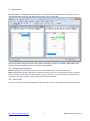
Modbus Poll uses a multiple document interface. That means several windows can be opened. Each one
with different data contents from different slave devices at the same time.
This picture shows two open windows. One reading 10 Holding registers from address 4000 (44001) and
another reading 10 Holding registers from address 2000 (42001).
3.1 Help from anywhere
Press F1 and get context sensitive help on a topic associated with the current selected item.
SHIFT + F1 invokes a special “help mode” in which the courser turns into a help courser (arrow + question
mark). The user can then select a visible object in the user interface, such as a menu item, toolbar button,
or window. This opens help on a topic that describes the selected item.
3.2 Alias cells
Here you can type any text for designation of the value cells. You can also copy/paste text from Excel cells.
http://www.modbustools.com
7
Modbus Poll User manual
3.3 Value cells
Show the data values of the Modbus registers. If you double click a value cell a dialog box lets you write a
new value to the slave device. Typing a number in a value cell shows the dialog as well. It is possible to
select the used Modbus function used to write the value.
The check box “Close dialog on Response ok” is used to automatically close the dialog box when a value is
successfully sent. This is convenient when a lot of values are to be changed. In that way it is fast to select a
new cell and then type a new value again.
3.4 Change color and font
Select the cells to be changed and then right click. Then a context menu is shown with 3 options to change
colors and font.
http://www.modbustools.com
8
Modbus Poll User manual
Colorize for better overview.
3.5 Open a new window
To open another window you have 3 options:
Press CTRL+N
Select new in the file menu
Press
on the tool bar
http://www.modbustools.com
9
Modbus Poll User manual
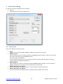
4 Connection dialog
To open the connection dialog you have 2 options:
Press F3
Select connect from the connection menu
4.1 Connection
There are 5 different connection types:
1. Serial:
Modbus over serial line. RS232 or RS485. A USB serial converter can be used.
2. Modbus TCP/IP:
Select TCP/IP if you want to communicate with a MODBUS TCP/IP network. In this case, slave ID is
the same as the Unit ID used in MODBUS TCP/IP.
The port number is default 502.
If the connection fails then try if you can ping your device at the command prompt. If the ping
command fails then Modbus Poll fails too.
3. Modbus UDP/IP:
Select UDP/IP if you want to communicate with a MODBUS UDP/IP network. This is the same as
Modbus TCP/IP but the connection less UDP protocol is used instead.
4. Modbus RTU/ASCII over TCP/IP:
This is a RTU or ASCII message send over a TCP/IP network instead of serial lines.
5. Modbus RTU/ASCII over UDP/IP:
This is a RTU or ASCII message send over a UDP/IP network instead of serial lines.
http://www.modbustools.com
10
Modbus Poll User manual
Note: Connection type 3-5 is not standard Modbus as specified by www.modbus.org but they are
added for convenience.
Depending on your selection some other settings will be grayed.
4.2 Serial Settings
Use these parameters to set serial port settings. They are only available if connection type is “Serial Port”.
4.3 Mode
Use this option to select RTU or ASCII mode. Default RTU.
4.4 Response timeout
Response timeout specifies the length of time that Modbus Poll should wait for a response from a slave
device before giving up. Default is 1000ms.
4.5 Min delay between polls
This setting ensures a minimum delay until next request is transmitted no matter of the scan rate.
The resolution of this setting is approximately 15ms. It's possible on some computers to obtain better
resolution but not all.
Important: If you set this value lower than 20ms the 3.5 char time gap between response and a new
request can’t be guaranteed. This is because the Windows scheduler switch tasks every 10 - 20ms.
1. If you Polls several slaves in a serial RS485 network you should NOT set the value lower than 20ms.
This is to ensure the 3.5 char time gap.
2. In a TCP/IP network less than 20ms is ok.
3. Serial connection to only one slave device less than 20ms is ok.
4.6 Remote Server
Remote server settings are only available when use an Ethernet connection.
IP Address: Servers IP address. Default is local host 127.0.0.1
Port: Server port number. Default 502
Connect Timeout: Max time to use to establish a connection. Default 1000
4.7 Advanced settings
4.7.1 RTS Toggle
RTS Toggle specifies that the RTS line will be high if bytes are available for transmission. After all buffered
bytes have been sent, the RTS line will be low.
You can use this to switch direction if you have a 232/485 converter without automatic direction switch.
Warning:
The use of RTS controlled RS232/RS485 converters should be avoided if possible. It is difficult to
determine the exact time when to switch off the transmitter with non real-time operating systems like
Windows and Linux. If it is switched off to early characters might still sit in the FIFO or the transmit
register of the UART and these characters will be lost. Hence the slave will not recognize the message.
On the other hand if it is switched off too late then the slave's message is corrupted and the master will
not recognize the message.
4.7.2 DSR
DSR specify whether the DSR (data-set-ready) signal is monitored for output flow control. If this member is
TRUE and DSR is turned off, output is suspended until DSR is sent again.
http://www.modbustools.com
11
Modbus Poll User manual
4.7.3 CTS
CTS specify whether the CTS (clear-to-send) signal is monitored for output flow control. If this checkbox is
enabled and CTS is turned off, output is suspended until CTS is sent again.
4.7.4 DTR
DTR specifies whether the DTR will be enabled or disabled whenever the port is opened.
4.7.5 Remove Echo
If your device or RS232/RS485 converter echoes the chars just sent.
http://www.modbustools.com
12
Modbus Poll User manual
5 Read/Write definition
Use this command to define the data to be monitored for the active window.
To open the Read/Write Definition dialog you have 3 options:
Press F8
Select “Read/Write Definition” from the Setup menu
Press
on the tool bar
5.1 Slave ID
Range 1 to 255. (MODBUS protocol specifications say 247). The value 0 is also accepted to communicate
directly to a MODBUS/TCP or MODBUS/UDP device.
5.2 Function code
You can select 1 of 8 function codes.
5.2.1 Read functions
The data returned by the read functions are displayed on the grid window.
01: Read coils
(0x)
02: Read discrete inputs
(1x)
03: Read holding registers
(4x)
04: Read input registers
(3x)
http://www.modbustools.com
13
Modbus Poll User manual
5.2.2 Write functions
The write functions write the data displayed on the grid window.
05: Write single coil
(Writes to Coil status)
06: Write single register
(Writes to Holding registers)
15: Write multiple coils
(Writes to Coils)
16: Write multiple registers
(Writes to Holding registers)
5.3 Address
Addresses in the Modbus protocol are confusing! Some protocol specifications use the protocol/message
address and others use device addressing.
5.3.1 Protocol/message address
Some protocol specifications use the protocol/message address counting from 0 to 65535 along with a
function code. This is also what the new Modbus specifications use. This is the address inside the message
sent on the wire.
Modbus Poll use protocol/message address counting from 0 to 65535.
5.3.2 Device address
Some protocol specifications use device address/registers. Registers counts from 1. The first digit describes
the function to be used. That means the device address 40101 is identified by address 100. The “4” means
Holding registers and 4x registers counts from 1. And even more confusing: 4x means function code 03 and
3x means function code 04!
5.3.3 5 digits vs. 6 digits addressing
The address format 4x counts from 40001 to 49999. The next address is not 50000. In old days 9999
addresses was enough. There are cases where 9999 is not enough. Then a zero is added. 40101 become
400101 and so on. This is called 6 digits addressing or extended addressing.
This is not a problem with Modbus Poll. 410001 become 10000. The “4” is thrown away and the rest 10001
is decremented by 1 as we count from 0 instead of 1.
5.4 Address examples
These examples show how to setup Modbus Poll if a specification use device addresses.
5.4.1 Read Holding Registers
You want to read 20 registers from device address 40011 from slave ID 2 every 1000ms. From the “4” we
know this is function 03 “Read Holding Registers”.
- Slave ID = 2
- Function = ”03 Read Holding Registers (4x)”
- Address = 10 (11 minus 1)
- Quantity = 20
-
Scan rate = 1000
http://www.modbustools.com
14
Modbus Poll User manual
5.4.2 Read Discrete Inputs
You want to read 1000 coils from address 110201 from slave ID 5 every 500ms. From the “1” we know this
is function 02 “Read Discrete Inputs”
- Slave ID = 5
- Function = ”02 Read Discrete Inputs (1x)”
- Address = 10200 (10201 - 1)
- Quantity = 1000
- Scan rate = 500
5.5 Scan rate
The scan rate can be set from 0 to 3600000ms. Note that setting the scan rate lower than the transaction
time does not make sense. If a serial connection at 9600baud is used and 125 registers are requested the
transaction time is roughly 8 + 2 + 250 + 2 = 262ms + the gap (>3.5 char time) between the request and the
response. In this case setting the scan rate at e.g. 100ms do not make sense as the transaction time is at
least 262ms + delay in the slave (gap) + min time between polls. (Set in the connection dialog).
5.6 Read/Write Disabled
The ‘Read/Write Disabled’ check box can be used to temporary enable or disable the communication for
this window. A text (Disabled) is then shown along with the Tx and Error counters.
If 'Read/Write' is disabled you can make single requests with the ‘Read/Write Once’ button or press F6.
5.6.1 Disable on error
The ‘Disable on error’ check box is used to disable Read/Write in case of error.
5.7 Hide alias columns
The ‘Hide Alias Columns’ is used to hide all alias columns. This is convenient to make more space if they are
not used.
5.8 Address in cell
If enabled, the address is also shown in the value cell like: 2000 = 00000
http://www.modbustools.com
15
Modbus Poll User manual
5.9 PLC Addresses (Base 1)
This option will show the addresses as device address.
5.10 Enron/Daniel Mode
Enron or Enron/Daniels Modbus is Standard Modbus with a few "Vendor Extensions". The exact impact of
these extensions is context dependent, but most common Modbus commands works as expected. There
are some custom vendor-defined functions available - but few users expect or use them. The largest impact
has to do with how 32-bit data values are read/written.
Enron-Modbus defines two special 4x holding register ranges:
4x5001 to 4x5999 are assumed 32-bit long integers (4-bytes per register).
4x7001 to 4x7999 are assumed 32-bit floating points (4-bytes per register).
Dealing with 32-bit values in Modbus is NOT unique to Enron-MB. However, Enron-MB takes the debatable
step of returning 4-bytes per register instead of the 2-bytes implied by the term "holding register" in the
Modbus specification. This means a poll of registers 4x5001 and 4x5002 in Enron-Modbus returns 8-bytes
or two 32-bit integers, whereas Standard Modbus would only return 4-bytes or one 32-bit integer treated
as two 16-bit integers. In addition, polling register 4x5010 in Enron-MB returns the tenth 32-bit long
integer, whereas Standard Modbus would consider this 1/2 of the fifth 32-bit long integer in this range.
5.11 Rows
Specify the number of rows in the grid you prefer.
http://www.modbustools.com
16
Modbus Poll User manual
6 Display formats
Mark the cells to be formatted. Select one of the 16 display formats from the display menu.
6.1 Native Modbus registers
The 16 bit Modbus registers can be displayed in 4 different modes.
Signed.
Unsigned.
Hex.
Binary.
6.2 32 bit long
This combines 2 16bit Modbus registers. It can be displayed in 4 different word/byte orders.
Long AB CD
Long CD AB
Long BA DC
Long DC BA
Example:
Byte Order: AB CD
The decimal number 123456789 or in hexadecimal 07 5B CD 15
Order as they come over the wire in a Modbus message: 07 5B CD 15
6.3 32 bit floating
This combines 2 16bit Modbus registers. It can be displayed in 4 different word/byte orders.
Float AB CD
Float CD AB
Float BA DC
Float DC BA
Example:
Byte Order: AB CD
The floating point number 123456.00 or in hexadecimal 47 F1 20 00
Order as they come over the wire in a Modbus message: 47 F1 20 00
6.4 64 bit double
This combines 4 16bit Modbus registers. It can be displayed in 4 different word/byte orders.
Double AB CD EF GH
Double GH EF CD AB
Double BA DC FE HG
Double HG FE DC BA
Example:
Byte Order: AB CD EF GH
The floating point number 123456789.00 or in hexadecimal 41 9D 6F 34 54 00 00 00
Order as they come over the wire in a Modbus message: 41 9D 6F 34 54 00 00 00
http://www.modbustools.com
17
Modbus Poll User manual
7 Save/Open Workspace
If you open many related Modbus windows it is convenient to save a snapshot of the current layout of all
open and arranged Modbus Windows in one workspace.
A workspace (*mbw) is a file that contains display information and file names of all open windows. Not the
actual contents. To do this, go to File-> Save Workspace.
When you open a workspace file, Modbus Poll opens all Modbus Windows and displays them in the layout
that you saved.
http://www.modbustools.com
18
Modbus Poll User manual
8 Test center
The purpose of this test dialog is to help MODBUS slave device developers to test the device with any string
of their own composition.
The list box displays the transmitted data as well as the received data.
You can have several test strings in the pull down list box. When you have entered a string then press the
"Add to List" button then the string is added to the list.
The selected string is sent when the "Send" button is pressed.
With the "Save list" button you can store the strings in a text file.
Check the "Add Check” check box if you want to add a CRC or LRC to the end of the input string.
When using the test center you may want to disable communication from other windows. Check the
“Read/Write disable” check box in “Read/Write Definition” dialog. Setup->Read/Write Definition.
8.1 ASCII Example
String in the combo box:
3A 30 31 30 33 30 30 30 30 30 30 30 41
The transmitted string if LRC is added
3A 30 31 30 33 30 30 30 30 30 30 30 41 46 32 0D 0A
A CR LF pair are also added.
8.2 TCP/IP Example
Read 10 holding registers.
00 00 00 00 00 06 01 03 00 00 00 0A
The first 6 bytes are the TCP/IP header.
8.3 Test center string file
With a text editor such as notepad or similar you can prepare strings to be used in the test.
The first line in the file must be the string ‘Test Center’. This is how Modbus Poll knows that the file is the
correct format. Press “Open list” to open the prepared text file.
8.3.1 Content of a string list
Modbus Poll
3A 30 31 30 33 30 30 30 30 30 30 30 41
3A 30 32 30 33 30 30 30 30 30 30 30 41
3A 30 33 30 33 30 30 30 30 30 30 30 41
8.4 Copy
Use the Copy button to copy selected Tx/Rx strings to the clipboard.
The SHIFT and CTRL keys can be used together with the mouse to select and deselect strings, select groups
of strings, and select non-adjacent strings.
Hint:
Leave this window open while doing other commands.
http://www.modbustools.com
19
Modbus Poll User manual
9 Modbus Data logging
You can log data to either a text file or direct to Microsoft Excel.
9.1 Text file
Select Log from the setup menu or use short cut keys: Alt+L
Each Modbus Window logs to its individual text file.
When you want to stop the data logging then select the logging off command on the setup menu.
9.1.1 Log Rate
Each read: Write a log line for all Modbus requests. Log frequency as scan rate.
Select: Specify the log rate in seconds. Independent of scan rate.
Remark: If the scan rate is e.g. 10000ms it makes no sense to set a 1 sec log rate as data are logged
only when new data are ready.
9.1.2 Delimiters
As delimiter you can use one of following options:
Fixed width: Means that the values are organized in columns.
Comma: Values separated by a comma.
Tab: Values separated by a tab.
9.1.3 Log if data changed only
Specify that a new log line is written only if any data is changed since last log.
9.1.4 Log Errors
Specify that errors such a timeout etc. are logged.
http://www.modbustools.com
20
Modbus Poll User manual
9.1.5 Log Date
Specify that the current date is added to the log time.
9.1.6 Start Log when ok is pressed
Specify that logging is started when ok button is pressed. Otherwise the log setup is just stored when *mbp
file is saved.
9.1.7 Start Log when *mbp is opened
Specify that logging is automatically started when a *.mbp file is opened.
9.1.8 Flush to file immediately
This ensures that log lines are not cashed in the file system but physical written immediately.
9.1.9 Append
Specify that logs are appended to selected file. Otherwise a new file is created.
Example of a text file with fixed width:
22:28:13
22:28:14
22:28:15
22:28:16
<40001>
<40001>
<40001>
<40001>
17395
17396
17394
13350
0
1
1
1
0
0
0
0
0
0
0
0
0
0
2
4
0
0
55
0
0
0
0
0
0
0
0
0
0
0
0
0
You can import the data in an Excel spreadsheet.
http://www.modbustools.com
21
Modbus Poll User manual
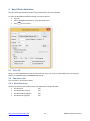
9.2 Microsoft Excel
This feature requires that Microsoft Excel is installed. Excel 2003 log is limited to 65535 logs as this is the
max number of rows in an Excel sheet. Excel 2007 is limited to 1,048,576 rows. Each Modbus Window logs
to its individual Excel sheet.
Select Excel Log from the setup menu or use short cut keys: Alt+X
Do not touch the Excel sheet while logging as this will interrupt the logging.
9.2.1 Log Rate
Each read: Write a log line for all Modbus requests. Log frequency as scan rate.
Select: Specify the log rate in seconds. Log is independent of scan rate.
Remark: If the scan rate is e.g. 10000ms it makes no sense to set a 1 sec log rate as data are logged
only when new data are ready.
Stop after: Specify the number of log lines. Note that Excel 2003 is limited to 65,536 rows and Excel
2007 1,048,576 rows.
9.2.2 Header information
Insert header: Information is inserted in the top most 3 lines in the Excel sheet.
o Alias cells in top row: Insert alias names in row 3.
o Poll definition: Insert ID, Function etc. in row 2.
o Name: Insert a log name in row 1.
http://www.modbustools.com
22
Modbus Poll User manual
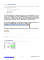
Excel log with header information.
http://www.modbustools.com
23
Modbus Poll User manual
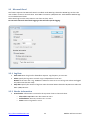
10 Communication traffic
Select the menu Display->Communication to show the traffic on the serial line or Ethernet cable. Use the
stop button to temporary stop the update for inspection.
Use the copy button to copy selected line to the clipboard.
Note:
This window show only data sent and received by Modbus Poll. You can’t use it as a data sniffer.
Hint:
Leave this window open while doing other commands.
http://www.modbustools.com
24
Modbus Poll User manual
11 OLE/Automation
Automation (formerly known as OLE Automation) makes it possible for one application to manipulate
objects implemented in another application.
An Automation client is an application that can manipulate exposed objects belonging to another
application. This is also called an Automation controller.
An Automation server is an application that exposes programmable objects to other applications. Modbus
Poll is an automation server.
That means you can use any program that supports Automation such as Visual Basic, Excel etc. to interpret
and show the MODBUS data according to your specific requirements.
11.1 Excel example
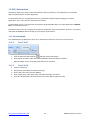
You should display the Developer tab or run in developer mode when you want to write macros.
11.1.1
Excel 2007
1. Click the Microsoft office button
and then click Excel options.
2. Click popular and then select the show Developers tab in the ribbon check box.
Note the ribbon is part of the Microsoft fluent user interface.
11.1.2
1.
2.
3.
4.
3.
Excel 2010
Click on the file tab.
Click options. Excel Options window will open.
On the left pane click Customize Ribbon.
On the right pane, under Main Tabs, check the Developer check box.
Click OK. The Developer tab should now show in the ribbon (right most tab).
http://www.modbustools.com
25
Modbus Poll User manual
11.1.3
Excel sample code
This example opens two windows. One reading registers and another reading Coils.
Modbus Poll is hidden but you can show it by uncomment the “ShowWindow” line. This will show one of
the windows.
An example is also included with the Modbus Poll installation.
Start -> All Programs -> Modbus Poll -> Examples
Public doc1 As Object
Public doc2 As Object
Public app As Object
Dim res As Integer
Dim n As Integer
Private Sub StartModbusPoll_Click()
Set app = CreateObject("Mbpoll.Application")
Set doc1 = CreateObject("Mbpoll.Document")
Set doc2 = CreateObject("Mbpoll.Document")
' Read 10 Holding Registers every 1000ms
res = doc1.ReadHoldingRegisters(1, 0, 10, 1000)
' Read 10 Coil Status every 1000ms
res = doc2.ReadCoils(1, 0, 10, 1000)
‘ doc1.ShowWindow()
app.Connection = 1 ' Modbus TCP/IP
app.IPAddress = "127.0.0.1" ' local host
app.ServerPort = 502
app.ConnectTimeout = 1000
res = app.OpenConnection()
End Sub
Private Sub Read_Click()
Cells(5, 7) = doc1.ReadResult() 'Show results for the requests
Cells(6, 7) = doc2.ReadResult()
For n = 0 To 9
Cells(5 + n, 2) = doc1.SRegisters(n)
Next n
For n = 0 To 9
Cells(18 + n, 2) = doc2.Coils(n)
Next n
End Sub
http://www.modbustools.com
26
Modbus Poll User manual
11.2 Connection Functions/Properties
The following properties and functions do the same as you setup in the connection dialog (F3).
11.2.1
Connection
Connection selects the desired connection. A serial port or one of the Ethernet connections can be
selected.
Property Connection as Integer
Valid values:
0
Serial port
1
Modbus TCP/IP
2
Modbus UDP/IP
3
Modbus ASCII/RTU over TCP/IP
4
Modbus ASCII/RTU over UDP/IP
11.2.2
BaudRate
Applicable only for Connection = 0
Property BaudRate as Long
Valid values:
300
600
1200
2400
4800
9600
14400
19200
38400
56000
57600
115200
128000
256000
Default value = 9600
Example:
BaudRate = 9600
11.2.3
DataBits
Applicable only for Connection = 0
Property DataBits as Integer
Valid values:
7
8
Default value = 8
Example:
DataBits = 8
http://www.modbustools.com
27
Modbus Poll User manual
11.2.4
Parity
Applicable only for Connection = 0
Property Parity as Integer
Valid values:
0 = None
1 = Odd
2 = Even
Default value = 2
Example:
Parity = 2
11.2.5
StopBits
Applicable only for Connection = 0
Property StopBits as Integer
Valid values:
1
2
Default value = 1
Example:
StopBits = 1
11.2.6
SerialPort
Applicable only for Connection = 0
Property SerialPort as Integer
Valid values:
1…255
Default value = 1
Example:
SerialPort = 1
11.2.7
ResponseTimeout
The ResponseTimeout specifies the length of time in ms that Modbus Poll should wait for a response from a
slave device before giving up.
Property ResponseTimeout as Integer
Valid values:
50…100000
Default value = 1000
Example:
ResponseTimeout = 1000
11.2.8
ServerPort
Applicable only for Connection = 1…4
Property ServerPort as Long
Valid values:
0…65535
Default value = 502
Example:
ServerPort = 502
http://www.modbustools.com
28
Modbus Poll User manual
11.2.9
ConnectTimeout
The ConnectTimeout specifies the length of time that Modbus Poll should wait for a TCP/IP connection to
succeed.
Applicable only for Connection = 1…4
Property ConnectTimeout as Integer
Valid values:
100…30000ms
Default value = 1000ms
Example:
ConnectTimeout = 1000
11.2.10
IPVersion
Applicable only for Connection = 1…4
Property IPVersion as Integer
Valid values:
4
IP Version 4
6
IP Version 6
Default value = 4
Example:
IPVersion = 4
11.2.11
OpenConnection
Opens the connection selected with the Connection property.
Function OpenConnection() As Integer
Return Value:
For error 3-5: Please check if you have the latest serial port driver.
0 = SUCCESS
1 = Serial Port not available
3 = Serial port. Not possible to get current settings from port driver.
4 = Serial port. Serial port driver did not accept port settings.
5 = Serial port. Serial port driver did not accept timeout settings.
12 = TCP/UDP Connection failed. WSA start up
13 = TCP/UDP Connection failed. Connect error
14 = TCP/UDP Connection failed. Timeout
15 = TCP/UDP Connection failed. IOCTL
17 = TCP/UDP Connection failed. Socket error
21 = TCP/UDP Connection failed. Address information
Example how to open a Modbus TCP/IP connection:
Public app As Object
Dim res As Integer
Set app = CreateObject("Mbpoll.Application")
app.Connection = 1 ' Select Modbus TCP/IP
app.IPVersion = 4
app.IPAddress = “192.168.1.27”
app.ServerPort = 502
app.ConnectTimeout = 1000
app.ResponseTimeout = 1000
res = OpenConnection()
http://www.modbustools.com
29
Modbus Poll User manual
Example how to setup a serial connection:
Public app As Object
Dim status As Integer
‘ Create an object to Modbus Poll
Set app = CreateObject("Mbpoll.Application")
app.Connection = 0
app.SerialPort = 1
app.BaudRate = 9600
app.Parity = 0
app.Mode = 0
app.ResponseTimeout = 1000
status = app.OpenConnection()
11.2.12
‘
‘
‘
‘
‘
‘
Mode is serial port
Com port 1
9600 baud
None parity
RTU mode
Wait 1000ms until give up
CloseConnection
Function CloseConnection() As Integer
Return Value
Zero if success. Nonzero value if failed.
http://www.modbustools.com
30
Modbus Poll User manual
11.3 Read Functions
The following functions do the same as you setup in the read/write definition dialog (F3). Read functions
are associated with a Modbus Poll document. (The window with data)
Example:
First a Modbus Poll document is needed.
Public doc As Object
Set doc = CreateObject("Mbpoll.Document")
res = doc.ReadCoils(1, 0, 100, 1000) ‘ Read 100 coils every 1000ms
Remarks:
You must create a Read before you can use properties to get data.
11.3.1
ReadCoils
Function ReadCoils(SlaveID As Integer, Address As Long, Quantity As Integer, ScanRate As Long) As Integer
Return Value
True if success. False if not success
Parameters
SlaveID,
The slave address 1 to 255
Address,
The data address (Base 0)
Quantity,
The number of data. 1 to 2000
ScanRate,
0 to 3600000ms
11.3.2
ReadDiscreteInputs
Function ReadDiscreteInputs(SlaveID As Integer, Address As Long, Quantity As Integer, ScanRate As Long)
As Integer
Return Value
True if success. False if not success
Parameters
SlaveID,
The slave address 1 to 255
Address,
The data address (Base 0)
Quantity,
The number of data. 1 to 2000
ScanRate,
0 to 3600000ms
11.3.3
HoldingRegisters
Function ReadHoldingRegisters(SlaveID As Integer, Address As Long, Quantity As Integer, ScanRate As
Long) As Integer
Return Value
True if success. False if not success
Parameters
SlaveID,
The slave address 1 to 255 (247 is max according to MODBUS specification)
Address,
The data address (Base 0)
Quantity,
The number of data. 1 to 125
ScanRate,
0 to 3600000ms
http://www.modbustools.com
31
Modbus Poll User manual
11.3.4
InputRegisters
Function ReadInputRegisters(SlaveID As Integer, Address As Long, Quantity As Integer, ScanRate As Long)
As Integer
Return Value
True if success. False if not success
Parameters
SlaveID,
The slave address 1 to 255
Address,
The data address (Base 0)
Quantity,
The number of data. 1 to 125
ScanRate,
0 to 3600000ms
11.3.5
ShowWindow
ShowWindow()
As default Modbus document windows are hidden. The ShowWindow function makes Modbus Poll visible
and show the document with data content.
11.3.6
Byte order
Property ByteOrder As Integer
Description
Sets the byte order used by Longs, Floats and Doubles properties.
0 = AB CD (Default)
1 = CD AB
2 = BA DC
3 = DC BA
Example for Longs:
Byte Order: AB CD
The decimal number 123456789 or in hexadecimal 07 5B CD 15
Order as they come over the wire in a Modbus message: 07 5B CD 15
Syntax
ByteOrder [=newvalue]
http://www.modbustools.com
32
Modbus Poll User manual
11.3.7
ReadResult
Use this property to check if communication established with Read is running successful.
Property ReadResult As Integer
Return Value:
0 = SUCCESS
1 = TIMEOUT ERROR
2 = CRC ERROR
3 = RESPONSE ERROR (The response was not the expected slave id, function or address)
4 = WRITE ERROR
5 = READ ERROR
6 = PORTNOTOPEN ERROR
10 = DATA UNINITIALIZED
11 = INSUFFICIENT BYTES RECEIVED
81h = ILLEGAL FUNCTION
82h = ILLEGAL DATA ADDRESS
83h = ILLEGAL DATA VALUE
84h = FAILURE IN ASSOCIATED DEVICE
85h = ACKNOWLEDGE
86h = BUSY, REJECTED MESSAGE
87h = NAK-NEGATIVE ACKNOWLEDGMENT
11.3.8
WriteResult
Return a write result as an integer.
Use this function to check if a write was successful. The value is DATA_UNINITIALIZED until the result from
the slave is available. See ReadResult for a list of possible values.
Property WriteResult As Integer
http://www.modbustools.com
33
Modbus Poll User manual
11.4 Automation data properties
The below properties are used to set or get values in the internal write/read arrays in Modbus Poll. The
Index used is not a Modbus Address. The Index always counts from 0 no matter of the address used. The
data properties are associated with a Modbus Poll document. (The window with data)
Example 1:
doc is assumed created first. See Excel example.
doc.SRegisters(0) = 1
doc.SRegisters(1) = 10
doc.SRegisters(2) = 1234
‘Write 3 registers stored in Modbus Poll internal array
‘to Modbus address 100 (40101)
res = doc.WriteMultipleRegisters(1, 100, 3)
Example 2 with floating point values:
doc.Floats(0) = 1.3
doc.Floats(2) = 10.5
doc.Floats(4) = 1234.12
res = doc. WriteMultipleRegisters(1, 0, 6) ‘Write the 6 register stored in Modbus Poll
6 Registers are written as float is 32 bit wide.
11.4.1
Coil
Property Coils(Index As Integer) As Integer
Description
Sets a coil in the write array structure or return a coil from the read array
Syntax
Coils(Index) [=newvalue]
11.4.2
Signed Register
Property SRegisters(Index As Integer) As Integer
Description
Sets a register in the write array structure or return a register from the read array.
Syntax
SRegisters (Index) [=newvalue]
11.4.3
Unsigned Register
Property URegisters(Index As Integer) As Long
Description
Sets a register in the write array structure or return a register from the read array.
Syntax
Object. URegisters (Index) [=newvalue]
http://www.modbustools.com
34
Modbus Poll User manual
11.4.4
Long
Property Longs(Index As Integer) As Long
Description
Sets a long in the write array structure or return a long from the read array.
Syntax
Longs (Index) [=newvalue]
11.4.5
Float
Property Floats(Index As Integer) As Single
Description
Sets a float in the write array structure or return a float from the read array.
Syntax
Floats (Index) [=newvalue]
11.4.6
Double
Property Doubles(Index As Integer) As Double
Description
Sets a double in the write array structure or return a double from the read array.
Syntax
Doubles (Index) [=newvalue]
http://www.modbustools.com
35
Modbus Poll User manual
11.5 Automation Write Functions
The write functions write the values stored in the array filled by the properties. The functions are
associated with a Modbus Poll document. (The window with data)
11.5.1
WriteSingleCoil
Function WriteSingleCoil(SlaveID As Integer, Address As Long) As Integer
Return Value
True if write array is ready and the data are sent. False if array empty or error in parameters.
The controlling application is responsible for verifying the write operation by reading back the value
written.
Parameters
SlaveID,
The slave address 0 to 255
Address,
The data address (Base 0)
Description
Writes the first coil stored in the write array.
Function 05 is used.
11.5.2
WriteSingleRegister
Function WriteSingleRegister (SlaveID As Integer, Address As Long) As Integer
Return Value
True if write array is ready and the data are sent. False if array empty or error in parameters.
The controlling application is responsible for verifying the write operation by reading back the value
written.
Parameters
SlaveID,
The slave address 0 to 255
Address,
The data address (Base 0)
Description
Writes the first register stored in the write array.
Function 06 is used.
11.5.3
WriteMultipleCoils
Function WriteMultipleCoils(SlaveID As Integer, Address As Long, Quantity As Integer) As Integer
Return Value
True if write array is ready and the data are sent. False if array empty or error in parameters.
The controlling application is responsible for verifying the write operation by reading back the values
written.
Parameters
SlaveID,
The slave address 0 to 255
Address,
The data address (Base 0)
Quantity,
The number of data. 1 to 1968
Description
Write the coils stored in the write array.
Function 15 is used.
http://www.modbustools.com
36
Modbus Poll User manual
11.5.4
WriteMultipleRegisters
Function WriteMultipleRegisters(SlaveID As Integer, Address As Long, Quantity As Integer) As Integer
Return Value
True if write array is ready and the data are sent. False if array empty or error in parameters.
The controlling application is responsible for verifying the write operation by reading back the value
written.
Parameters
SlaveID,
The slave address 0 to 255
Address,
The data address (Base 0)
Quantity,
The number of data. 1 to 123
Description
Write the registers stored in the write array.
Function 16 is used.
http://www.modbustools.com
37
Modbus Poll User manual
12 Exception and error messages
Modbus Exceptions and error messages are display in red text in 2nd line in each window.
12.1 Modbus Exceptions
Modbus exceptions are errors returned from the slave device.
Illegal Function
Illegal Data Address
Illegal Data Value
Slave Device Failure
Acknowledge
Slave Device Busy
The function code received in the query is not an allowable action for the server
(or slave). This may be because the function code is only applicable to newer
devices, and was not implemented in the unit selected. It could also indicate
that the server (or slave) is in the wrong state to process a request of this type,
for example because it is not configured and is being asked to return register
values.
The data address received in the query is not an allowable address for the
server (or slave). More specifically, the combination of reference number and
transfer length is invalid. For a controller with 100 registers, a request with
offset 96 and length 4 would succeeds, a request with offset 96 and length 5 will
generate exception 02.
A value contained in the query data field is not an allowable value for server (or
slave). This indicates a fault in the structure of the remainder of a complex
request, such as that the implied length is incorrect. It specifically does NOT
mean that a data item submitted for storage in a register has a value outside
the expectation of the application program, since the MODBUS protocol is
unaware of the significance of any particular value of any particular register.
An unrecoverable error occurred while the server (or slave) was attempting to
perform the requested action.
Specialized use in conjunction with programming commands. The server (or
slave) has accepted the request and is processing it, but a long duration of time
will be required to do so. This response is returned to prevent a timeout error
from occurring in the client (or master). The client (or master) can next issue a
Poll Program Complete message to determine if processing is completed.
Specialized use in conjunction with programming commands. The server (or
slave) is engaged in processing a long–duration program command. The client
(or master) should retransmit the message later when the server (or slave) is
free.
http://www.modbustools.com
38
Modbus Poll User manual
12.2 Modbus Poll error messages
Timeout error
The response is not received within the expected time.
Response Error
CRC Error
Write Error
The response is not the expected one. Different slave ID.
The CRC value of the received response is not correct.
This is an error reported by the serial driver. This could happen if a USB/RS232/485
converter is used and the USB cable is unplugged. There are 4 types:
Break condition
I/O error
Serial connection error
Output buffer overflow
Read Error
Write error using TCP/IP connection is normally caused by lost connection.
This is an error reported by the serial driver. There are 6 types:
Framing error
Character buffer overrun
Parity error
Input buffer overflow
I/O error
Break condition
Read error using TCP/IP connection is normally caused by lost connection.
Insufficient bytes
received
Byte count error
The response is not the expected length.
The byte count in the response is not correct. Compared to the expected.
http://www.modbustools.com
39
Modbus Poll User manual