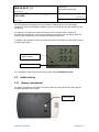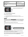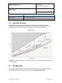
1
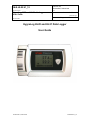
IN-E-HL20-V1_12
Rotronic AG
Bassersdorf, Switzerland
Document code
Unit
HygroLog HL20 and HL21 data logger:
User Guide
Instruction Manual
Document Type
Page
Document title
1 of 17
HygroLog HL20 and HL21 Data Logger
User Guide
© 2010-2011; Rotronic AG
IN-E-HL20-V1_12
IN-E-HL20-V1_12
Rotronic AG
Bassersdorf, Switzerland
Document code
Unit
HygroLog HL20 and HL21 data logger:
User Guide
Document title
Instruction Manual
Document Type
Page
2 of 17
Table of contents:
1. Overview.................................................................................................................................. 3
1.1
General ................................................................................................................................ 3
2. General description ................................................................................................................ 4
2.1
Models ................................................................................................................................. 4
2.2
Required accessories .......................................................................................................... 4
2.3
Batteries ............................................................................................................................... 4
2.4
Real time clock .................................................................................................................... 5
2.5
Memory ................................................................................................................................ 5
2.6
Function key ........................................................................................................................ 5
2.7
Status indicator (LED).......................................................................................................... 5
2.8
Service and data connector ................................................................................................. 6
2.9
Optional display ................................................................................................................... 6
2.10 Operating limits .................................................................................................................... 6
2.11 Configurable settings ........................................................................................................... 6
2.12 Factory default settings ....................................................................................................... 8
2.13 Data logging ......................................................................................................................... 8
3. Operation................................................................................................................................. 9
3.1
Front panel with optional display ......................................................................................... 9
3.2
Initial start-up ..................................................................................................................... 10
3.3
Recording and displaying data (models without display) .................................................. 12
3.4
Displaying and recording data (models with display) ........................................................ 12
3.5
Practical advice for measuring temperature and humidity ................................................ 13
4. Maintenance .......................................................................................................................... 13
4.1
Periodic calibration check .................................................................................................. 13
4.2
Firmware updates .............................................................................................................. 14
5. Technical data ...................................................................................................................... 14
5.1
Specifications ..................................................................................................................... 14
5.2
Dew point accuracy ........................................................................................................... 16
6. Accessories .......................................................................................................................... 16
7. Supporting documents ........................................................................................................ 17
8. Document releases .............................................................................................................. 17
© 2010-2011; Rotronic AG
IN-E-HL20-V1_12
IN-E-HL20-V1_12
Rotronic AG
Bassersdorf, Switzerland
Document code
Unit
HygroLog HL20 and HL21 data logger:
User Guide
Document title
Instruction Manual
Document Type
Page
3 of 17
Applicability:
This manual is valid for instruments with firmware version 1.0x (check using the ROTRONIC HW4
software, Device Manager). Examples: 1.0a, 1.0b. Changes in the last character of the version
number reflect minor changes in the internal software of the instrument that do not affect the
manner in which the instrument should be operated.
1.
Overview
1.1
General
The HygroLog HL20 data logger can record up to 20,000 pairs of relative humidity and
temperature values within the range of 0 to 100 %RH and -10 to 60°C (14 to 140°F).
The HygroLog HL21 data logger can record up to 20,000 temperature values within the range of
-10 to 60°C (14 to 140°F). Models with the optional LC display are limited 0 to 50°C (32 to 122°F).
Temperature is measured with a Pt100 RTD. Relative humidity is measured with a ROTRONIC
Hygromer IN1 capacitive sensor. Both sensors are internal and there is no apparent probe.
Both the HL20 and HL21 require three AA batteries (1.5V) for power. Depending on both the log
interval and the display option, these data loggers can record data over a time period of up to 20
months without replacing the batteries.
Configuration of the HL20 and HL21, as well as the downloading and viewing of recorded data,
requires a PC with the ROTRONIC HW4 software installed as well as a service cable such as the
AC3006
Based on the ROTRONIC AirChip 3000 digital technology the HL20 and HL21 offer the following
features:
Unit system: metric or English
Real time clock (runs for up to 4 hours without the 3 AA batteries after initial charge)
Calculation of the dew or frost point (calculated parameter can be displayed but not recorded)
Optional LC display (%RH, temperature) with battery charge indicator and message bar
Function key: starts and stops data logging, turns optional LC display on and off
Status indicator (LED): flashes green when logging, flashes red for out-of-limit values or a
logger problem
Humidity temperature calibration and adjustment
Simulator mode (used to validate the data recording function)
Note: Instructions for using the HW4 software are not included in this manual. These instructions
are shipped separately on the software CD ROM.
© 2010-2011; Rotronic AG
IN-E-HL20-V1_12
IN-E-HL20-V1_12
Rotronic AG
Bassersdorf, Switzerland
Document code
Unit
HygroLog HL20 and HL21 data logger:
User Guide
Document title
2.
General description
2.1
Models
Instruction Manual
Document Type
Page
4 of 17
Basic models without display
o
o
HygroLog HL-20: relative humidity and temperature logger, function key, status indicator
(LED), internal sensors protected by a slotted cover.
HygroLog HL-21: temperature data logger, function key, status indicator (LED), internal
Pt100 RTD
Models with display
o
o
2.2
HygroLog HL-20D: same as HL20, LC display with backlight, message bar and battery
charge indicator
HygroLog HL-21D: same as HL21, LC display with backlight, message bar and battery
charge indicator
Required accessories
The following accessories are required in order to be able to configure the logger and to
download and view the recorded data:
- Cable AC3006 or equivalent (plugs into a USB port of the PC)
- PC with the ROTRONIC HW4 software installed (version 2.4.0 or higher)
2.3
Batteries
All models ship with three AA batteries which must be inserted first (see battery replacement).
Note: To conserve battery power, models with the LC display are shipped with the Display Sleep
function enabled and set to 1 minute (see Software Functions). When the function key has not
been pressed for some time (in this case 1 minute), the display sleep function automatically turns
the display off. The display can be temporarily turned on at any time by pressing on the function
key.
2.3.1
Battery lifetime
The battery lifetime depends on the manner in which the HL20 or HL21 is being used. The
following examples are based on the following assumptions:
● Fresh set of AA batteries (2900 mAh)
● Display backlight turned off (if applicable)
● Log interval set to 30 minutes
© 2010-2011; Rotronic AG
IN-E-HL20-V1_12
IN-E-HL20-V1_12
Rotronic AG
Bassersdorf, Switzerland
Document code
Unit
HygroLog HL20 and HL21 data logger:
User Guide
Document title
Instruction Manual
Document Type
Page
5 of 17
Battery lifetime in months
Models w/o LC display
20
Models with LC display, display sleep function set to 1 minute
13
Models with LC display, display sleep function disabled
5
2.4
Real time clock
After inserting a fresh set of batteries for the first time, the real time clock must be adjusted prior
to using the HL20 or HL21 (see “Operation”). The real time clock is powered from a large
capacitor and can run for up to 4 hours without the batteries. Removing the battery for an
extended period of time will cause the logger to completely lose track of the date and time.
Because of the requirement to always keep track of the date and time, the HL20 and HL21 do not
have a power on/off switch.
2.5
Memory
All models use a non-volatile EEPROM internal memory to hold the measurement data. The
memory cannot be removed from the data logger.
Memory capacity is as follows:
HL20: 20,000 pairs of relative humidity and temperature values
HL21: 20,000 temperature values
2.6
Function key
The function key is used as follows:
Long key press: press the key for a few seconds to start or stop data logging.
Short key press: depending on the configuration settings of the display (display sleep
function) a short key press turns on and off the optional LC display.
For more details, see “Operation”
2.7
Status indicator (LED)
The status indicator consists of a green and red LED. The green side of the LED flashes every 5
seconds when logging is active. The red side of the LED flashes every 5 seconds when a
measured value is out of limits (see “Configurable settings”) or when the logger requires attention
(low battery, memory full, major sensor failure – such as open or shorted sensor)
© 2010-2011; Rotronic AG
IN-E-HL20-V1_12
IN-E-HL20-V1_12
Rotronic AG
Bassersdorf, Switzerland
Document code
Unit
HygroLog HL20 and HL21 data logger:
User Guide
Document title
2.8
Instruction Manual
Document Type
Page
6 of 17
Service and data connector
The service / data connector (mini-USB type) can be accessed after removing the back cover
(see Operation). The connector gives access to the data logger UART digital interface (Universal
Asynchronous Receiver Transmitter).
Configuring the data logger or retrieving the recorded data requires cable AC3006 or equivalent.
One end of the cable plugs into the service / data connector. The other end plugs into the USB of
a PC with the ROTRONIC HW4 software installed. See “Initial start-up” for the location of the
service / data connector.
2.9
Optional display
The optional LC display has a backlight which can be enabled or disabled when configuring the
data logger.
o
HL20D: depending on the configuration of the logger, the LC display shows relative humidity
and temperature or the dew / frost point and temperature. The top line displays humidity
(%RH or the dew / frost point)
o
HL21D: the LC display shows temperature.
The LC display can be configured to show the measured or calculated values with either one or
two decimals.
Note: the LC display is automatically turned on when the data logger is connected to the USB
port of a PC by means of cable AC3006 or equivalent.
2.10 Operating limits
Models without display:
● -10…60°C with the factory supplied alkaline batteries
● 0…100 %RH, non condensing
Models with display:
● 0…50°C with the factory supplied alkaline batteries
● 0…100 %RH, non condensing
2.11 Configurable settings
Configuration of the data logger by the user and access to its functions requires a PC with the
ROTRONIC HW4 software (version 2.4.0 or higher) installed. Service cable AC3006 is used to
connect the service / data connector to a USB port of the PC.
© 2010-2011; Rotronic AG
IN-E-HL20-V1_12
IN-E-HL20-V1_12
Rotronic AG
Bassersdorf, Switzerland
Document code
Unit
HygroLog HL20 and HL21 data logger:
User Guide
Document title
Instruction Manual
Document Type
Page
7 of 17
Instructions regarding the configuration of the data logger and access to its functions are provided
in the following manuals:
E-M-HW4v3-F2-018
E-M-HW4v3-Main (§ 7.5)
E-M-HW4v3-A2-001
2.11.1 Relative humidity symbol and temperature unit
Both the symbol representing relative humidity and the temperature can be configured to suit
local requirements.
2.11.2 Calculated parameter
HL20: the data logger can be set to compute one of the following psychrometric parameters.
o
o
Dew point (Dp)
Frost point (Fp)
Notes:
When the optional display is configured to show the calculated parameter, either the
symbol Dp or the symbol Fp appear to the left of the numerical value, depending on
whether the dew point or frost point was selected. For values below freezing, the symbol
Fp indicates that the value is a frost point (above ice) as opposed to being a dew point
(above liquid).
The data logger cannot be used to record either the dew point or the frost point
2.11.3 Alarm function (out-of-limit value)
The alarm function can be enabled or disabled for each of the measured or calculated
parameters. High and low value can be associated with each parameter so as to define out-oflimits values. A hysteresis value can also be entered for each parameter. The hysteresis value is
used for both the low and the high alarm conditions.
The data logger has a red LED which flashes when the value of any parameter is out-of-limits.
The LED stops flashing when the value returns to normal..
Log files do not record the existence of an alarm condition. However, when the contents of a log
file are viewed as a data table with the HW4 software, values that correspond to an alarm
condition are printed over a red background, based on the alarm settings that HW4 downloaded
from the logger.
2.11.4 Display-Sleep function
Using the Display Sleep function can substantially extend the lifetime of the battery. When the
Display Sleep function is active, the LC display of the data logger stays blank.
The optional display of the data logger can be set to be always on. In this case, the display can
be turned on and off manually with the function key. The display can also be set to automatically
go blank after 1, 5, 10 or 20 minutes.
© 2010-2011; Rotronic AG
IN-E-HL20-V1_12
IN-E-HL20-V1_12
Rotronic AG
Bassersdorf, Switzerland
Document code
Unit
HygroLog HL20 and HL21 data logger:
User Guide
Instruction Manual
Document Type
Page
Document title
8 of 17
The data logger suspends the Display Sleep function whenever the function key is pressed. The
function is also suspended when the data logger is connected to the USB port of a PC by means
of cable AC3006.
2.12 Factory default settings
Configurable Settings
Factory default
Unit system
Psychrometric calculation
Display resolution
Metric, except USA: English
No calculation
1 decimal
Display Sleep function
Display backlight
Displayed parameters
Communication protocol
Device name
Enabled, display automatically turns off after 1 minute
Off
%RH and temperature or temperature only
RO-ASCII
Instrument model
Functions
Factory default
Humidity / temperature adjustment
Device write protection
Enabled
Disabled
Limit humidity to 100 %RH
Out-of-limit value alarm
Data recording
Major sensor failure alarm
Simulator mode
Enabled
Disabled
Stopped (loop mode – 10 min. interval)
Enabled (cannot be disabled)
Disabled
2.13 Data logging
● Function overview:
The main characteristics of the data logging function are as follows:
-
Relative humidity values are recorded with a resolution of 0.1%RH
Temperature values are recorded with a resolution of 0.05˚C / 0.09˚F
Memory capacity: 20,000 single values or value pairs
Adjustable log interval: from 5 seconds to 1 hour, in increments of 5 seconds
Two data recording modes: Loop and Start-Stop
Note: Any recorded data present in the data logger memory is automatically erased whenever a
new recording session is started.
© 2010-2011; Rotronic AG
IN-E-HL20-V1_12
IN-E-HL20-V1_12
Rotronic AG
Bassersdorf, Switzerland
Document code
Unit
HygroLog HL20 and HL21 data logger:
User Guide
Instruction Manual
Document Type
Page
Document title
9 of 17
● Data recording modes:
Loop
: when the memory is full the logger dumps the oldest data sample and keeps
recording. The memory retains the most recent data.
Start-Stop
: the logger stops recording data as soon as the memory is full
Data recording can be stopped at any time by pressing on the function key (long key press) or
with the ROTRONIC HW4 software.
● Recorded parameters:
Depending on the model, the data logger records either temperature only or relative humidity and
temperature. A calculated value such as dew point cannot be recorded by the HL20 but it can be
added to the humidity and temperature data after downloading the recorded data to a PC with the
HW4 software. See the following HW4 manual: E-M-HW4v3-F2-018
● Date and time:
The data logger has an internal real time clock that is used to associate a date and time stamp
with each data record.
When data recording is either started or stopped using the ROTRONIC HW4 software, the real
time clock is automatically synchronized with the PC clock.
● Log file format (data download to a PC with HW4):
The recorded data can be saved as a file to a PC using either HW4 or another communications
software. When using HW4, the file can be either formatted as a text file (extension TXT) or as an
encrypted binary file (extension LOG). The LOG file format can only be read with HW4 and
complies with the FDA / GAMP rules regarding electronic records and electronic signatures.
3.
Operation
3.1
Front panel with optional display
Status indicator
(LED)
Function key
© 2010-2011; Rotronic AG
IN-E-HL20-V1_12
IN-E-HL20-V1_12
Rotronic AG
Bassersdorf, Switzerland
Document code
Unit
HygroLog HL20 and HL21 data logger:
User Guide
Document title
Instruction Manual
Document Type
Page
10 of 17
The LC display has a backlight which can enabled or disabled as part of the data logger
configuration. When the backlight is enabled, it turns on for a few seconds after pressing on the
function key.
The upper line corresponds to relative humidity or dew / frost point and the bottom line
corresponds to temperature. In the event of an alarm (out-of-limit value) the display shows the
symbol [ ! ] to the right of the value and the LED indicator flashes red.
In addition to the measured values, the display also provides information such as battery charge
and data logger status.
3-segment battery
charge indicator
Message bar
For configuration instructions see the following HW4 manual: E-M-HW4v3-F2-018.
3.2
3.2.1
Initial start-up
Battery compartment
The battery compartment is located on the back panel and can be opened after loosening the
screw that holds the cover in place
Cover screw
© 2010-2011; Rotronic AG
IN-E-HL20-V1_12
IN-E-HL20-V1_12
Rotronic AG
Bassersdorf, Switzerland
Document code
Unit
HygroLog HL20 and HL21 data logger:
User Guide
Instruction Manual
Document Type
Page
Document title
11 of 17
Insert three fresh AA alkaline batteries in the battery
compartment. Be sure to observe the polarity.
3.2.2
Initial configuration (all models)
Required Hardware and software
PC with the ROTRONIC HW4 software installed (version 2.4.0 or higher)
Cable AC3006 or equivalent (connects the data logger service / data connector to a PC
USB port)
IMPORTANT:
After installing the HW4 software and prior to running HW4, connect cable AC3006 to a USB port
of the PC. The PC will detect the cable and ask for the appropriate driver. The ROTRONIC USB
driver (ftdibus.inf) is located in a folder named USB_Driver which is in the HW4 installation folder.
For detailed instructions see documents E-M-HW4v3-Main (§ 7.3: USB port) and E-M-HW4v3F2-018
Setting the Real Time Clock (required configuration step)
The real time clock of the data logger should be set to agree with the date and time of the HW4
PC.
Service and data connector (mini USB type)
Use cable AC3006 to connect the data logger to a USB port of the HW4 PC. Start HW4 and
discover the data logger by selecting with the mouse the following command in the menu bar:
Devices and Groups > Search for Master Devices > USB Masters.
When the Data logger icon appears, left click with the mouse on the (–) sign located to the left of
the icon. This displays the functional modules available for the data logger. Click on the Device
Manager module. For additional instructions, see document E-M-HW4v3-F2-018.
© 2010-2011; Rotronic AG
IN-E-HL20-V1_12
IN-E-HL20-V1_12
Rotronic AG
Bassersdorf, Switzerland
Document code
Unit
HygroLog HL20 and HL21 data logger:
User Guide
Instruction Manual
Document Type
Page
Document title
12 of 17
Other initial configuration steps
Other initial configuration steps include the following:
-
Temperature measurement unit
Log interval
Recording mode (start-stop or loop)
For additional instructions, see document E-M-HW4v3-F2-018.
3.2.3
Optional display configuration
To conserve battery power, models with a display are shipped with the Display Sleep function
enabled (set to 1 minute) and with the display backlight disabled. When configured in this manner
the data logger can record data for extended periods of time
For additional instructions regarding the configuration of the display, see document
E-M-HW4v3-F2-018.
3.3
Recording and displaying data (models without display)
To start or stop recording data, press on the function key for a few seconds. When the
data logger is recording data, the status indicator flashes green every 5 seconds
The ROTRONIC HW4 software is required to view the measured or calculated data on a PC
monitor. Connect the data logger to the HW4 PC as explained under “Initial Start-up”. HW4 is
also required to download and save the recorded data to disk. For additional instructions, see
document E-M-HW4v3-F2-018.
3.4
Displaying and recording data (models with display)
Displaying data
When the display sleep function is enabled, the display goes blank after some time in order to
conserve battery power.
To view the measured or calculated data, press briefly on the function key. When the
display sleep function is not enabled, the display can be manually turned off by
pressing briefly on the function key.
Start or stop recording data
To start or stop recording data, press on this key for a few seconds. When the data
logger is recording data, this is indicated by the display message bar and by the LED
indicator flashes green every 5 seconds
© 2010-2011; Rotronic AG
IN-E-HL20-V1_12
IN-E-HL20-V1_12
Rotronic AG
Bassersdorf, Switzerland
Document code
Unit
HygroLog HL20 and HL21 data logger:
User Guide
Document title
Instruction Manual
Document Type
Page
13 of 17
The ROTRONIC HW4 software is required to view the measured or calculated data on a PC
monitor. Connect the data logger to the HW4 PC as explained under “Initial Start-up”. HW4 is
also required to download and save the recorded data to disk. For additional instructions, see
document E-M-HW4v3-F2-018.
3.5
Practical advice for measuring temperature and humidity
The most common source of error when measuring relative humidity is a difference between
the temperature of the probe and the temperature of the environment. At a humidity condition
of 50 %RH, a temperature difference of 1 C (1.8 F) typically results in an error of 3 %RH on
relative humidity.
When using the data logger, it is good practice to allow for sufficient for temperature
equilibration with the environment. The larger the initial temperature difference between the
probe and the environment to be measured, the more time temperature equilibration requires.
This can be monitored with the optional display.
In extreme situations, condensation may occur on the sensors when the data logger is colder
than the environment. As long as the humidity / temperature limits of the humidity sensor are
not exceeded, condensation does not alter the calibration of the sensor. However, the sensor
has to dry out before it can provide a valid measurement.
Non-moving air is an excellent insulator. When there is no air movement, surprising differences in
temperature and humidity can noted over short distances. Air movement at the probe generally
results in measurements that are both faster and more accurate.
4.
Maintenance
4.1
Periodic calibration check
Both the Pt 100 RTD temperature sensor and associated electronics are very stable and
should not require any calibration after the initial factory adjustment.
Long term stability of the ROTRONIC Hygromer humidity sensor is typically better than 1
%RH per year. For maximum accuracy, calibration of the HL20 should be verified every 6 to
12 months. Applications where the data logger is exposed to significant pollution may require
more frequent verifications.
Note: calibrating and adjusting the data logger typically require a humidity-temperature
generator or other specialized equipment that may not be available to all users.
© 2010-2011; Rotronic AG
IN-E-HL20-V1_12
IN-E-HL20-V1_12
Rotronic AG
Bassersdorf, Switzerland
Document code
Unit
HygroLog HL20 and HL21 data logger:
User Guide
Instruction Manual
Document Type
Page
Document title
14 of 17
Procedure for adjusting the data logger with the ROTRONIC HW4 software:
Use cable AC3006 to connect the service connector of the data logger to the USB port of
a PC with the ROTRONIC HW4 software installed. Note that the ROTRONIC USB driver
must be installed on the PC as explained in the HW4 manual E-M-HW4v3-Main
Start HW4 on the PC and search for the data logger (HW4 Main Menu Bar > Devices and
Groups > Search for USB Masters).
After finding the data logger with HW4, expand the device tree to see the data logger
functions. Select Probe Adjustment.
For further instructions see HW4 manual E-M-HW4v3-A2-001
4.2
Firmware updates
Firmware updates will be available on the ROTRONIC website for downloading. Firmware files
are given a name that shows both to which device the file applies and the version number of the
firmware. All firmware files have the extension HEX. Procedure for updating the firmware:
Use cable AC3006 to connect the service connector of the data logger to the USB port of
a PC with the ROTRONIC HW4 software installed. Note that the ROTRONIC USB driver
must be installed on the PC as explained in the HW4 manual E-M-HW4v3-Main
Copy the firmware update file from the ROTRONIC website to the PC.
Start HW4 software on the PC and search for the data logger (HW4 Main Menu Bar >
Devices and Groups > Search for USB Masters).
After finding the data logger, expand the device tree to see the data logger functions.
Select Device Manager. In the Device Manager menu bar select Tools > Firmware
Update. For instructions see document E-M-HW4v3-F2-018
5.
Technical data
5.1
Specifications
General
HL20 / HL21
Device type
Humidity-temperature data logger with internal sensor(s)
Battery type
3 x AA (1.5 V) alkaline
Battery life time
Depends on log interval and other settings. Examples based on a 30 minutes log
interval:
Models w/o LC display: 20 months
Models with LC display, display sleep function set to 1 minute: 13 months
Low battery indication
Yes (with HW4 software or with optional display)
Humidity measurement
HL20
Sensor
ROTRONIC Hygromer ® IN1
Measuring range
0…100 %RH
Measurement accuracy at 23 °C
±0.8 %RH
Repeatability
0.3 %RH
Long term stability
< 1 %RH / year
Response time
Typical 3 min. (depends on air flow)
© 2010-2011; Rotronic AG
IN-E-HL20-V1_12
IN-E-HL20-V1_12
Rotronic AG
Bassersdorf, Switzerland
Document code
Unit
HygroLog HL20 and HL21 data logger:
User Guide
Instruction Manual
Document Type
Page
Document title
15 of 17
Temperature measurement
HL20 / HL21
Sensor
Pt100 RTD, IEC 751 1/3 class B
Measuring range
-10...60°C
Measurement accuracy at 23 °C
±0.2 °C
Repeatability
0.05°C
Long term stability
< 0.1°C / year
Response time
Typical 10 min. (depends on air flow)
Calculated parameters
HL20
Psychrometric calculations
Dew or frost point (user configurable setting)
Start-up time and data refresh rate
HL20 / HL21
Start-up time
1.9s (typical)
Data refresh rate
1.7s (typical)
Data recording and download
HL20 / HL21
Recorded parameter(s)
HL20: relative humidity and temperature, HL21: temperature
Recording media
Internal EEPROM non volatile, not removable
Recording capacity
HL20: 20,000 value pairs, HL21: 20,000 values
Real time clock
Yes, adjustable via PC
Logging modes
Start-stop (recording stops when memory is full
Loop: oldest data is dumped to make room for latest data
Log interval
Min. 5 sec, up to1 hour in 5 sec. increments
Interface for data download
Internal connector, located under protective cover
Service and data connector
HL20 / HL21
Interface type
UART (Universal Asynchronous Receiver Transmitter)
Maximum service cable length
5 m (16.4 ft)
General specifications
HL20 / HL21
Optional display
LC, 1 or 2 decimals resolution, backlight, alarm and low battery indication
LED indicator
5 sec, green flash when recording data
5 sec. red flash for out-of-limit value or logger problem
Housing material
ABS
Housing protection grade
HL20: IP 40, HL21: IP65
Overall dimensions
130 x 72 x 32 mm (5.1 x 2.8 x 1.3”)
Weight
About 210 g (7.4 oz)
Conformity with standards
HL20 / HL21
CE / EMC immunity
EMC Directive 2004/108/EG: EN 61000-6-1: 2007, EN 61000-6-2: 2005
EN 61000-6-3: 2007, EN 61000-6-4: 2007
Solder type
Lead free (RoHS directive)
FDA / GAMP directives
compatible
© 2010-2011; Rotronic AG
IN-E-HL20-V1_12
IN-E-HL20-V1_12
Rotronic AG
Bassersdorf, Switzerland
Document code
Unit
HygroLog HL20 and HL21 data logger:
User Guide
Instruction Manual
Document Type
Page
Document title
16 of 17
Environmental limits
HL20 / HL21
Operating limits
-10….60 °C (models w/o display), 0….50 °C (models with display)
0…100 %RH, non condensing
Critical environments
Humidity sensor: as per DV04-14.0803.02 - Critical chemicals
5.2
Dew point accuracy
The HL20 can be configured to calculate either the dew point or frost point based on the
measurement of relative humidity and temperature. The accuracy of this conversion varies,
depending on the humidity and temperature conditions as shown in the graph below:
Example: at a temperature of 20 ˚C, a dew point value of -37 ˚C is measured with an accuracy of
± 1.0 ˚C or better.
6.
Accessories
For accessories and parts such as the HW4 configuration software, service cables, calibration
accessories and spare dust filters, please see document E-M-HC2-accessories
© 2010-2011; Rotronic AG
IN-E-HL20-V1_12
IN-E-HL20-V1_12
Rotronic AG
Bassersdorf, Switzerland
Document code
Unit
HygroLog HL20 and HL21 data logger:
User Guide
Document Type
Page
Document title
7.
Instruction Manual
17 of 17
Supporting documents
Document File Name
Contents
E-M-HC2-accessories
Accessories and parts for probes, indicators and transmitters
E-M-HW4v3-DIR
List of the HW4 manuals
E-M-HW4v3-Main
HW4 software version 3: General instructions and functions
common to all devices
E-M-HW4v3-F2-018
HW4 software version 3: Device Manager and Data Logging HL20 / HL21 data logger
E-M-HW4v3-A2-001
HW4 software version 3: Probe Adjustment function AirChip 3000
devices
E-M-AC3000-CP
AirChip 3000 Communication Protocol
E-M-CalBasics
Temperature and humidity calibration basics
Instructions for using the ROTRONIC humidity standards
E-T-HumiDefs
Humidity Definitions
Note: All document file names have an extension corresponding to the document release
number. This extension is not shown in the above table.
8.
Document releases
Doc. Release
Date
Notes
_10
Mar. 5, 2010
Original release
_11
Jun. 20, 2010
Updated document to HW4 software v.3
_12
Mar. 9, 2011
Corrected typing error in document
© 2010-2011; Rotronic AG
IN-E-HL20-V1_12