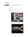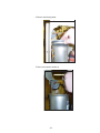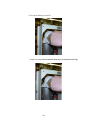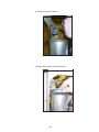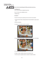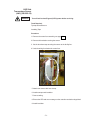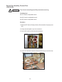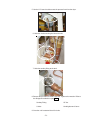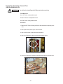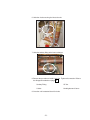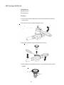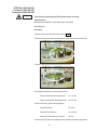
1
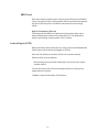
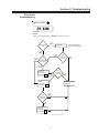
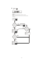
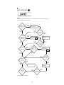
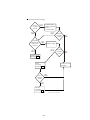
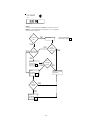
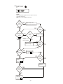
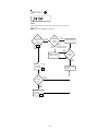
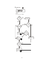
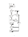
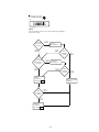
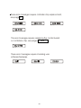
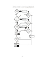
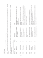
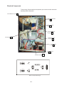
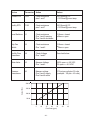
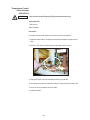
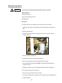
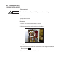
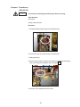
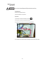
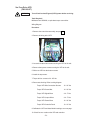
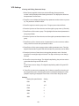
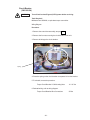
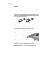
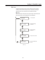
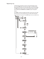
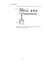
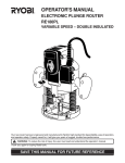
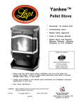
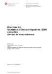
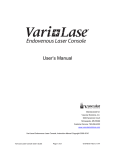
Coolant Distribution Unit (CDU, Chiller)
Jaguar Platform
Thermo Manual P/N U00862
Rev. 03/08/06
Troubleshooting
FRU Replacement
Table of Contents
Preface
After-sale Support ..................................................................................... 3
Warranty .................................................................................................. 3
Section I Safety
Warnings .................................................................................................. 5
EMO Circuit .............................................................................................. 6
Lockout/Tagout (LOTO) ............................................................................. 6
Section II Troubleshooting
Error Code Troubleshooting ....................................................................... 7
VFD Faults ............................................................................................. 20
Monitoring Fluid Loss ............................................................................. 22
Section III FRU List
FRU List ................................................................................................. 23
Section IV FRU Replacement
Electrical Components ........................................................................... 40
Control Box Assembly ............................................................................ 42
Keypad ................................................................................................... 43
Dryer Tube .............................................................................................. 44
Fill Port Screen ...................................................................................... 45
HFE Filter Bag Kit .................................................................................. 46
Pump Inline Dryer ................................................................................... 51
Tank Level Switch ................................................................................... 52
Pump ..................................................................................................... 53
Temperature Control Valve Assembly ...................................................... 57
Temperature Control Valve Actuator ........................................................ 62
Water Flow Transducer ........................................................................... 63
HFE Side Temperature Sensor (rtd1) ...................................................... 64
Pressure Transducers ........................................................................... 65
Drip Pan Level Switch Kit ....................................................................... 66
Pressure Regulator ................................................................................. 67
Plumbing, Pressure Regulator to Temperature Control Valve .................. 69
Plumbing, Facility Inlet Pipe ................................................................... 70
H2O Side Temperature Sensor (rtd2) ...................................................... 71
Return Pipe Assembly, Process Flow ..................................................... 72
Supply Pipe Assembly, Process Flow .................................................... 74
PRV Cartridge ........................................................................................ 76
VFD Filter, Contactor, Transformer .......................................................... 77
EMO Thermostat .................................................................................... 78
VFD ........................................................................................................ 79
VFD Settings .......................................................................................... 80
Circuit Breaker ........................................................................................ 81
Temp Option Board ................................................................................. 82
Chip Replacement .................................................................................. 83
TC-400 Controller .................................................................................... 84
-1-
LON Adapter Board ................................................................................. 86
Sight Tube Kit ......................................................................................... 87
Torque Specification Sheet ...................................................................... 89
Swagelok Tube Fitting Instructions ......................................................... 90
Section V Controller Loops
Main Loop .............................................................................................. 93
Engineering Loop .................................................................................... 94
Factory Reset ......................................................................................... 95
Section VI Facility Drawings
873-592-22 ............................................................................................. 96
873-611-00 .............................................................................................. 99
WARRANTY
-2-
Preface
After-sale Support
Thermo Electron Corporation is committed to customer service both during and
after the sale. If you have questions concerning the CDU operation, contact our
Sales Department. If your CDU fails to operate properly, or if you have questions concerning spare parts contact our Service Department.
(800) 258-0830
(603) 436-9444
Fax: (603) 436-8411
Before calling, please obtain the following information:
- CDU BOM number
- CDU serial number
- CDU software version
- voltage of power source
The CDU’s BOM and serial number label are located on the label on the fronttop of the CDU. See Service Manual for instructions on how to display the
software version.
Warranty
CDUs have a warranty against defective parts and workmanship for 24 months
from date of shipment. See back pages for more details.
-3-
This page intentionally left blank.
-4-
Section I Safety
Warnings
Make sure you read and understand all instructions and safety precautions
listed in this manual before installing or operating your CDU. If you have any
questions concerning the operation of your CDU or the information in this
manual, contact our Sales Department for assistance.
DANGER
DANGER indicates an imminently hazardous situation which, if not avoided,
will result in serious injury or death. This signal word is limited to the most
extreme situations.
WARNING
WARNING indicates a potentially hazardous situation which, if not avoided,
could result in serious injury or death.
CAUTION
CAUTION indicates a potentially hazardous situation which, if not avoided,
may result in minor or moderate injury. It may also be used to alert against
unsafe practices.
Performance of installation, operation, or maintenance procedures
other than those described in this manual may result in a hazardous
situation and may void the manufacturer’s warranty.
Transport the CDU with care. Sudden jolts or drops can damage the
CDU.
Do not attempt to defeat any of the interlock switches or safety features
built into the CDU.
Observe, and never remove, all warning labels.
Never operate damaged or leaking equipment.
Never operate the CDU without cooling fluid in the fluid reservoir.
Process fluid are subject to environmental regulatory restrictions. Do
not dispose into the environment. In the United States use proper OSHA
approved location for disposal.
Use remote lockout tag-out procedures prior to servicing the CDU. Make
sure the CDU is off before connecting or disconnecting the power cord
or other cables.
Always turn off the CDU and disconnect the power cord from the power
source before performing any service or maintenance procedures, or
before moving the CDU.
Always empty the fluid reservoir before moving the CDU.
Never operate equipment with damaged power cords.
Refer service and repairs to a qualified technician.
-5-
EMO Circuit
Each of the following safeties is part of the test system Emergency Off (EMO)
circuit. The tripping of either of these safeties will cause power to be dropped to
the CDU by the test system. The EMO circuit should not exceed 10A @
24VDC.
High Air Temperature (TSH-101)
This safety opens the EMO circuit when the air temperature safety switch
detects a temperature inside the CDU greater than 70°C. The temperature
switch is self-resetting at a temperature of 54°C or below.
Lockout/Tagout (LOTO)
Before performing Chiller maintenance, the energy sources associated with the
Chiller system must be lockout and tagged out (LOTO).
Since the CDU itself has no electrical LOTO, lock out power remotely.
Electrical LOTO can be provided by:
Disconnecting main power at the facility power source prior to the system
controller cabinet.
The unit does not provide LOTO for the facility water flow. An external usersupplied device is required.
In addition, follow all local facility LOTO directives.
-6-
Section II Troubleshooting
Error Code
Troubleshooting
LEVEL WARN
LED
Error Message
Cause:
Upper low level warning switch closed for at least 3 seconds.
Fluid Level
OK?
NO
Also see Monitoring
Fluid Loss on page 22.
Add fluid
YES
NO
NO
Is
switch/wiring
defective?
Did
message
clear?
YES
YES
Replace
switch/wiring.
See page 52
50.
NO
Did
message
clear?
YES
Reset
controller.
See page 95
87.
Did
message
clear?
Return to normal
operation
YES
NO
Replace
controller.
See page 79.
-7-
Recalibrate
controller.
Refer to Teradyne
Service
Documentation
FILTER
LED
Error Message
Cause:
Return pressure greater than 10 psi for 1 minute.
NOTE: Normally indicates the filter in the reservoir needs
changing.
Remove filter.
See page 44.
Does filter
need
changing?
YES
Change filter.
See page 44.
46
NO
NO
Reset
controller.
See page 95
87.
Did error
message
clear?
YES
Return to normal
operation
Did
message
clear?
NO
YES
Recalibrate
controller.
Refer to Teradyne
Service
Documentation
Replace
controller.
See page 84
79.
-8-
LOW HFE PRES
LED
Error Message
Cause:
A major leak has developed or the unit supply pressure less than 20 psi for 30
seconds after pump / VFD start.
Is there any
evidence of a
leak?
YES
Repair the source
of the leak(s)
NO
Is VFD
displaying
an error
message?
NO
YES
NO
YES
Are
pressure
transducers
functional?
YES
Return to normal
operation
Troubleshoot VFD.
See page 20
22.
NO
Is pump
running?
Did error
message
clear?
Did error
message
clear?
YES
Replace
transducers.
65
See page 61.
NO
YES
NO
NO
Is VFD
Volt IN
correct?
NO
YES
Is VFD
Volt OUT
correct?
Did error
message
clear?
YES
Return to normal
operation
Correct Volt IN.
NO
Continued on next page
-9-
Did error
message
clear?
YES
Continued from previous page
Is VFD
Volt OUT
correct?
Correct V OUT.
Refer to Teradyne
Service
Documentation
NO
YES
NO
Is wiring
between VFD
and pump
correct?
NO
Did error
message
clear?
YES
Did error
message
clear?
YES
Replace wiring
NO
YES
Replace pump.
See page 53
51.
Reset
controller.
See page 95
87.
Did
message
clear?
Return to normal
operation
YES
NO
Replace
controller.
See page 84
79.
- 10 -
Recalibrate
controller.
Refer to Teradyne
Service
Documentation
LVL FAULT
LED
Error Message
Cause:
Lower low level warning switch open for at least 3 seconds
NOTE: The LEVEL WARN LED should also be on, if not replace
the level switch assembly
Fluid Level
OK?
NO
Also see Monitoring
Fluid Loss on page 22.
Add fluid
YES
NO
NO
Is
switch/wiring
defective?
Did
message
clear?
YES
YES
Replace
switch/wiring.
See page 52
50.
NO
Did
message
clear?
YES
Reset
controller.
See page 95
87.
Did
message
clear?
NO
Return to normal
operation
YES
Recalibrate
controller.
Refer to Teradyne
Service
Documentation
Replace
controller.
See page 79.
84
- 11 -
TEMP FAULT
LED
Error Message
Cause:
Fluid temperature higher than alarm setpoint value in
controller's setup loop.
NOTE: This is normally not a pump issue
Is
facility
water
adequate?
NO
Adjust facility water
temperature/flow/pressure
YES
Did
message
clear?
NO
Is
control valve
plunger full
down?
See page
62
58.
YES
NO
Is
voltage at
valve
~9½VDC?
Refer to
Teradyne Service
Documentation.
NO
YES
Adjust voltage.
YES
NO
Replace valve and
adjust. voltage.
Did
message
clear?
YES
NO
Is
pressure
across valve
correct?
NO
Adjust pressure.
See page 68
64.
YES
NO
Reset
controller.
See page 95
87.
Did
message
clear?
YES
Return to normal
operation
Did
message
clear?
NO
YES
Recalibrate
controller.
Refer to Teradyne
Service
Documentation
Replace
controller.
See page 84
79.
- 12 -
TEMP FAULT
LED
Error Message
Cause:
Fluid temperature lower than alarm setpoint value in controller's
setup loop.
NOTE: This is normally not a pump issue.
Is
control valve
plunger full
up?
See page
62
58
NO
YES
Is
voltage
NO Adjust voltage.
at valve
~0VDC?
Refer to
Teradyne Service
YES
Documentation.
NO
Replace valve/
adjust voltage.
Did
message
clear?
YES
Reset
controller.
See page 95
87.
Did
message
clear?
NO
Return to normal
operation
YES
Recalibrate
controller.
Refer to Teradyne
Service
Documentation
Replace
controller.
See page 84
79.
- 13 -
DRIP PAN
LED
Error Message
Cause:
Drip pan level switch is open.
Is there
fluid in
the drip
pan?
YES
Remove fluid
Check for leaks
NO
NO
NO
Is
switch/wiring
defective?
Did
message
clear?
YES
YES
Replace
switchs/wiring.
66
See page 62.
NO
Did
message
clear?
YES
Reset
controller.
95
See page 87.
Return to normal
operation
YES
Did
message
clear?
NO
Replace
controller.
See page 84
79.
- 14 -
Recalibrate
controller.
Refer to Teradyne
Service
Documentation
VFD FAULT
LED
Error Message
Cause:
Open relay on VFD.
Does VFD
display an
error?
YES
Troubleshoot VFD.
20
See page 32.
NO
NO
NO
Is
wiring
defective?
Did
message
clear?
YES
YES
Fix wiring
NO
Did
message
clear?
YES
Return to normal
operation
Reset
controller.
95
See page 87.
Did
message
clear?
NO
YES
Recalibrate
controller.
Refer to Teradyne
Service
Documentation
Replace
controller.
84
See page 79.
- 15 -
These error messages require checking the applicable
sensor and its associated wiring. If the error message does
not clear reset and/or replace the controller.
SENSOR FAIL
LED
Error Message
The reservoir fluid temperature probe RTD1 input is open or shorted,
84
see page 60.
Error Message
The coolant return pressure sensor input is out of range, see page 63.
67
Error Message
67
The coolant supply pressure sensor input is out of range, see page 63.
Error Message
The supply pressure is greater than 110 psi.
Error Message
The differential pressure equals a negative value for at least 3 seconds.
- 16 -
COMM DISC
LED
Error Message
Cause:
Communications lost for over 10 seconds while operating in
the remote mode.
Are all
connections
secure?
NO
Secure
connections
YES
NO
Are
commands
being sent to
the unit?
NO
NO
Reset
controller.
See page 87.
95
NO
YES
Send start
command.
YES
Did
message
clear?
Did
message
clear?
Did
message
clear?
YES
Return to normal
operation
YES
Recalibrate
controller.
Refer to Teradyne
Service
Documentation
Replace
controller.
See page 84
79.
- 17 -
These error messages require controller chip replacement,
83
see page 78.
Error Message
Error Message
Error Message
Error Message
This error message requires replacing the control board
83 and 79.
84
or controller's chip, see pages 78
Error Message
These error messages require checking user
software/hardware.
Error Message
Error Message
Error Message
- 18 -
Unit will not start, no error message displayed.
Is
1CB
closed?
NO
Close 1CB
YES
NO
Is
incoming
voltage and/or
phase to 1T
correct ?
NO
NO
NO
YES
Adjust voltage
and/or phase
YES
Is 1T
secondary
voltage
correct?
Did
display
come on?
Did
display
come on?
YES
Replace 1T.
See page 77
72.
NO
YES
Reset
controller.
See page 95
87.
Did
display
come on?
YES
Return to normal
operation
Did
message
clear?
NO
YES
Recalibrate
controller.
Refer to Teradyne
Service
Documentation
Replace
controller.
See page 84
79.
- 19 -
- 20 -
Under Voltage
Over Voltage
Motor Stalled
Motor Overload
Heatsink
OverTemp
Ground Fault
F005
F006
F007
F008
F013
Power Loss
F003
F004
Fault
Display
2
1
1
1
1
1
2
Type
For any other fault display contact Thermo.
A current path to earth ground
has been detected at one or more
of the drive output terminals.
Heatsink temperature exceeds
a predefined value.
Internal electronic overload trip.
Drive is unable to accelerate
motor.
DC bus voltage exceeded
maximum value.
DC bus voltage fell below the
minimum value.
DC bus voltage remained below
85% of nominal.
Description
Check the motor and external wiring to the drive output terminals
for a grounded condition.
1. Check for blocked or dirty heat sink VFD fins. Verify ambient
temperature has not exceeded 50°C(122°F)
2. Check fan.
An excessive motor load exists. Contact Thermo.
Check connections on VFD.
Monitor the AC line for high line voltage or transient conditions.
Bus overvoltage can also be caused by motor regeneration.
Extend the decel time or install dynamic brake option.
Monitor the incoming AC line for low voltage or line power
interruption.
1. Monitor the incoming AC line for low voltage or line power
interruption.
2. Check input fuses.
Action
Type 2- This type of fault may require VFD or motor repair, or is caused by wiring or programing errors. The cause of the fault must be corrected before the
fault can be cleared.
Type 1 - The VFD attempts to automatically reset the fault. If the condition that caused the fault is no longer present, the fault will be reset and the VFD will be
restarted.
A fault is a condition that stops the VFD. There are two fault types:
VFD Faults
- 21 -
Phase UW Short
Phase VW Short
F042
F043
I/O Board Fail
Phase UV Short
F041
F122
Phase W to Ground
F040
Power CDU
Phase V to Ground
F039
F070
Phase U to
Ground
F038
2
2
2
2
Failure has been detected in the
drive control and I/O section.
Failure has been detected in the
drive power section.
See F041
See F041
Excessive current has been
detected between these two
output terminals.
See F038
See F038
A phase to ground fault has been
detected between the drive and
motor in this phase.
1. Cycle power.
2. Replace drive if fault cannot be cleared.
1. Cycle power.
2. Replace drive if fault cannot be cleared.
1. Check the motor and drive output terminal wiring for a
shorted condition.
2. Replace drive if fault cannot be cleared.
1. Check the wiring between the drive and motor.
2. Check motor for grounded phase.
3. Replace drive if fault cannot be cleared.
Monitoring for Fluid
Loss
Each line on the Reservoir Gauge represents approximately 1/10 of a gallon.
On a routine basis check and record the fluid level. If the fluid level is dropping
at a rate faster than indicated by the specification then perform the following:
1. Ensure the Tank Fill Port and the Tank Auxiliary Port Cap are properly
installed and on hand tight.
2. Check all sanitary gaskets to insure that they are properly installed and
are on according to the Torque Specification Sheet on page 88.
3. Look for signs of a leak at all connections and solder joints.
4. If none of the above yield any results, use a Halogen Leak detector on
each connection and joint.
5. Check for leaks at the Test Equipment per your procedures.
Reservoir Gauge
- 22 -
Section III FRU List
Description
SYS HFE -20CDU
FRU CDU RETURN PIPE ASSY
FRU CDU FILTER BAG
FRU CDU FILTER O-RING
FRU CDU PUMP W/ GASKETS
FRU CDU PUMP SUCT LINE
FRU CDU INLINE DRIER
FRU CDU SUPPLY PIPE ASSY
FRU CDU FILL PORT SCREEN
FRU CDU PRESS REGULATOR
FRU CDU FLOW XDUCER
FRU CDU TEFLON PASTE
FRU CDU FACIL INLET PIPE
FRU CDU VALVE W/ACTUATOR
FRU CDU VLV ACTUATOR ONLY
FRU CDU INSUL TAPE
FRU CDU TANK LVL SWITCH
FRU CDU PRESS XDUCER
FRU CDU DRIP PAN SWITCH
FRU CDU RTD H2O SIDE
FRU CDU DRIER TUBE
FRU CDU RTD HFE SIDE
FRU CDU FILL PORT CAP
FRU CDU FILL PORT O-RING
FRU CDU PETES PLUG
FRU CDU CIRCUIT BREAKER
FRU CDU CONTACTOR
FRU CDU TRANSFORMER
FRU CDU VAR FREQ DRIVE
FRU CDU LON ADAPT BOARD
FRU CDU TEMP OPTION BRD
FRU CDU VFD FILTER
FRU CDU EMO THERMOSTAT
FRU CDU 1.5" SANIT GASKT
FRU CDU 2" SANIT GASKET
FRU CDU 1.5" SANIT CLMP
FRU CDU 2" SANIT CLMP
FRU CDU TC400 CNTRL BRD
FRU CDU EPROM SOFTWARE
FRU CDU PIPING TO MOD VLV
FRU PRV CARTRIDGE
FRU KEYPAD
FRU CDU DRIP PAN PLUG
FRU CDU ELECT BOX ASSY
FRU VFD BOX ASSU
FRU MOTOR OVERLOAD
FRU SIGHT TUBE KIT
Thermo
603099991705
093354
093355
093385
093356
093357
093449
093358
093386
093359
087773
093387
093360
093361
087774
093388
087775
087782
087776
087777
093362
087778
093397
093363
093384
087783
087784
087779
087785
087786
087787
087780
087788
093380
093381
093382
093383
087790
087791
093448
015779
015781
093498
087823
N/A
N/A
093703
- 23 -
Teradyne
873-592-00
360-900-00
360-900-01
360-900-02
360-900-03
360-900-04
360-900-05
360-900-06
360-900-07
360-900-08
360-900-09
360-900-10
360-900-11
360-900-12
360-900-13
360-900-14
360-900-15
360-900-16
360-900-17
360-900-18
360-900-19
360-900-20
360-900-21
360-900-22
360-900-23
360-900-24
360-900-25
360-900-26
360-900-27
360-900-28
360-900-29
360-900-30
360-900-31
360-900-32
360-900-33
360-900-34
360-900-35
360-900-38
360-900-39
360-900-40
360-900-41
360-900-42
360-900-57
360-900-58
N/A
N/A
360-966-15
Thermo
603099991706
093354
093355
093385
093356
093357
093449
093495
093386
093359
093493
093387
093496
093497
087774
093388
087775
087782
087820
087777
093362
087821
093397
093363
093384
087783
087784
087779
087785
087786
087787
087780
087788
093380
093381
093382
093383
087790
087791
093499
015779
015781
093498
087823
N/A
N/A
093703
Teradyne
873-611-00
390-900-00
360-900-01
360-900-02
360-900-03
360-900-04
360-900-05
360-900-50
360-900-07
360-900-08
360-900-51
360-900-10
360-900-52
360-900-53
360-900-13
360-900-14
360-900-15
360-900-16
360-900-54
360-900-18
360-900-19
360-900-55
360-900-21
360-900-22
360-900-23
360-900-24
360-900-25
360-900-26
360-900-27
360-900-28
360-900-29
360-900-30
360-900-31
360-900-32
360-900-33
360-900-34
360-900-35
360-900-38
360-900-39
360-900-59
360-900-41
360-900-42
360-900-57
360-900-58
N/A
N/A
360-966-15
NOTE: If two numbres are listed the second number applies to the 873-611-00 unit.
360-900-09 Transducer,Water Flow
360-900-51
360-900-13 Valve Actuator Only
360-900-15 Tank Level Switch
- 24 -
360-900-17 Sensor Kit, Drip Pan Level
360-900-54
360-900-18 RTD H2O Side
360-900-20 RTD HFE Side
360-900-55
- 25 -
360-900-26 Transformer
360-900-30 VFD Filter
360-900-16 Pressure Transducer
- 26 -
360-900-24 Circuit Breaker
360-900-25 Contactor
360-900-27 Var Freq Drive
- 27 -
360-900-28 LON Adapter Board
360-900-29 Temp Option Board
360-900-31 EMO Thermostat
- 28 -
360-900-58 Control Box Assembly
360-900-38 TC400 Control Board
360-900-00 Return Pipe Assembly, Process Flow
- 29 -
360-900-01 Filter Bag Kit
360-900-03 Pump with Gaskets
360-900-04 Pump Suction Line, with Gaskets
- 30 -
360-900-06, Supply Pipe Assembly
360-900-50
360-900-08 Pressure Regulator
360-900-11 Facility Inlet Pipe
360-900-52
- 31 -
360-900-12 Valve Assembly, Temperature Control (873-592-00 unit)
360-900-53 Valve Assembly, Temperature Control (873-611-00 unit)
360-900-19 Dryer Tube
- 32 -
360-900-32 Gasket 1½" / 360-900-33 Gasket 2"
360-900-34 Clamp, Sanitary Fitting 1½" / 360-900-35 Clamp, Sanitary Fitting 2"
360-900-23 Petes Plug
- 33 -
360-900-02 O-ring, Filter Housing
360-900-07 Fill Port Screen
360-900-10 Teflon® Paste
- 34 -
360-900-14 Tape, Insulating
360-900-57 Fitting, Drip Pan Plug
360-900-21 Fill Port Cap
- 35 -
360-900-40 Piping to Mod Valve
360-900-59
360-900-05 Pump Inline Dryer
Programmable Chip Extractor
- 36 -
360-900-42 Keypad
360-900-41 Pressure Relief Valve Cartridge
360-900-22 Service Kit, Fill Port Cap
- 37 -
360-966-15 Sight Tube Kit
- 38 -
Section IV FRU Replacement
CAUTION
WARNING
CAUTION
For personal safety and equipment reliability, the following procedures
should only be performed by a qualified technician. The following
steps assume the technician is knowledgable of all Swagelok initial
tightening and retightening procedures. Contact our Service Department for assistance.
Contact with hazardous voltage inside the chiller can cause severe
injury of death. Turn off and Lockout/Tagout (LOTO) power before
servicing. Have a qualified technician verify that line voltage is no
longer present within the unit after performing a LOTO procedure and
before working on system.
Performance maintenance and service procedures other than those
described in this manual may result in a hazardous situation.
- 39 -
Electrical Components
To access any of these electrical components you must remove the control box
assembly and the side panel.
Circuit Breaker see page 81
TC-400 Controller Board
see page 84
Temp Option Board
seepage 82
Programmable Chip
see page 83
VFD see page 79
EMO Thermostat
see page 78
VFD Filter see
page 72
Transformer see
page 77
Contactor see page 77
123 4 5
67 8 9
123 4 5
67 8 9
Bottom View (See Next Page)
- 40 -
Connector
Action
Values
Coolant RTD
J102
Check resistance
pins 1 and 7
100 Ohms @ 0°C
~110 Ohms @ room temp
Facility RTD
P103
Check resistance
pins 1 and 7
100 Ohms @ 0°C
~110 Ohms @ room temp
Level Switches
J1
Check resistance
Pins 1 and 2 warning
Pins 3 and 4 shut down
0 Ohms = closed
Ohms = open
Drip Pan
Switch
J2
Check resistance
Pins 1 and 2
0 Ohms = closed
Ohms = open
Facility Flow
Transducer
J4
Check Voltage
Pins 1 and 2
See chart below
Motor Valve
J5
Measure Voltage
Pins 1 and 2
100% open => 9.5 VDC
0% open = < 6.0 VDC
Pressure
Transducers
J6
Measure voltage
Pins 2 and 3 supply
Pins 5 and 6 return
37.5 psi per volt plus 0.5 volts
(example - 150 psi = 4.5 volts)
8
8
Device
Output (Hz)
200.00
150.00
100.00
50.00
5
10
15
20
25
Flow Rate (gpm)
- 41 -
30
35
Control Box Assembly
(360-900-58)
WARNING
Turn off and Lockout/Tagout (LOTO) power before servicing.
Tools Required:
#2 Philips Head Screwdriver
11/32" wrench
Wiring Diagram
Procedure:
1. Using #2 Philips Head, remove the 4
screws securing the control box assembly to the front of the unit.
2. Remove the single screw securing the
base of the control box to the unit's midframe.
3. Remove the 8 connectors at the bottom of
the control box.
4. At the pump motor, remove the wiring
running from the base of the control box.
5. Remove the 11/32 nut securing the ground
wire at the rear of the unit.
6. Slide the control box assembly out from the unit.
7. To reinstall, reverse the procedure.
Torque Control Box to Mid Pan, Bottom
Torque Control Box to Mid Pan, Top
Torque Control Box Assembly to Sides
14 - 16"-lbs
24 - 28"-lbs
24 - 28"-lbs
8. Rewire according to the wiring diagram.
9. Return the replaced control box assembly to Thermo Electron.
- 42 -
360-900-42 Keypad
Tools Required:
Screwdriver
11/32" wrench
Procedure:
1. Remove the 4 screws securing the keypad panel to the front of the unit.
2. Disconect ribbon cable from control board.
3. Remove the 11/32 grounding nut.
4. Peal the keypad off the panel.
5. When reinstalling, tighten gounding nut 14-16"-lbs.
- 43 -
Dryer Tube
(360-900-19)
When the cartridge color-change feature (blue to pink) reaches the bottom of
the top cap, the dryer tube needs changing.
WARNING
Turn off and Lockout/Tagout (LOTO) power before servicing.
Tools Required:
Tywrap cutter/scissors
Procedure:
1. Remove the top and bottom tubes from the dryer tube nipples.
2. Cut the ty-wrap.
3. Reverse the procedure to install a new dryer tube.
4. Once the unit is restarted check for leaks.
- 44 -
Fill Port Screen
(360-900-07)
WARNING
Turn off and Lockout/Tagout (LOTO) power before servicing.
Tools Required:
None
Procedure:
1. Remove the fill port cap by turning counterclockwise.
2. Remove the screen.
3. Replace the screen.
4. Reinstall the fill cap.
5. Once the unit is restarted check for leaks.
- 45 -
HFE Filter Bag Kit
(360-900-01)
WARNING
Turn off and Lockout/Tagout (LOTO) power before servicing.
Tools Required:
None
Procedure:
1. Crack open the reservoir fill to allow air into the tank.
2. Locate and then loosen the black knob on the clamp at the top of the filter
housing.
3. Remove the clamp. Note how the "T" is locked into position on the clamp.
T
- 46 -
4. Remove the lid and gasket.
5. Remove the spacer, handle up.
- 47 -
6. Pull out the old bag to remove it.
7. Install a new bag. Ensure that the paper tag is removed from the bag.
- 48 -
8. Reinstall the spacer, handle up.
9. Replace the lid gasket and reinsall the lid.
- 49 -
10. To reinstall a new bag push down on the lid and gasket when tightening the
black knob. Hand tighten until the gap matches the other two gaps.
11. Once the unit is restarted check for leaks.
12. Ensure the LED and error message on the controller are both extinguished.
- 50 -
Pump Inline Dryer
(360-900-05)
WARNING
Turn off and Lockout/Tagout (LOTO) power before servicing.
Tools Required:
9/16" wrench
Procedure:
For easier access to the assembly remove the unit from the cabinet.
1. Note orientation of dryer assembly.
2. Crack open the reservoir fill to allow air into the tank.
3. Use the 9/16" wrench to remove the Swageloks securing the dryer assembly
to the unit. To make removing the outer Swagelok easier, bend the inner
dryer line down to get it out of the way.
Inner Swagelok
Dryer
Outer Swagelok
Top View
4. Undo the two Velcro straps and remove the dryer assembly.
5. Install a new dryer assembly. Secure the Velcro straps first to prevent
bending the lines.
6. Connect the two ¼" lines and tighten the Swageloks per the tightening
procedure on page 90.
7. Once the unit is restarted check for leaks.
- 51 -
Tank Level Switch
(360-900-15)
WARNING
Turn off and Lockout/Tagout (LOTO) power before servicing.
Tools Required:
Adjustable wrench
Tywrap cutter/scissors
Procedure:
1. For easier access to the switch, remove the control box assembly, see page
42.
2. Undo the electrical "D" connector on the rear of the unit.
3. Remove the ty wraps.
4. Undo the green plastic fitting and remove the switch assembly from the
reservoir.
5. To reinstall a new assembly reverse the procedure. NOTE: To prevent cross
threading, install the new assembly into the reservoir only hand tight.
6. Once the unit is restarted check for leaks.
7. Ensure the LED and error message on the controller are both extinguished.
- 52 -
Pump (360-900-03)
WARNING
CAUTION
Turn off and Lockout/Tagout (LOTO) power before servicing.
Crack the fill cap to relieve any tank/system pressure.
Tools Required:
11/16" wrench
7/16" wrench
1/2" wrenchet.
Procedure:
For easier access to the pump remove the unit from the cabin
1. Drain the water. Refer to Teradyne Service Documentation for proper procedure.
2. Remove the control box assembly, see page 42.
3. Remove sanitary clamps from both ends of the elbow running from pump
discharge line to the plate exchanger.
- 53 -
4. Remove the clamps, elbow, and gaskets from the unit.
5. Remove the sanitary clamp on the pump's suction line.
6. Using a 11/16" wrench, remove the fitting from the pump's drain line.
- 54 -
7. Using a 7/16" wrench, remove the 6 bolts securing the pump plate to the unit.
8. Remove the pump and plate from the unit.
CAUTION
The pump weighs at least 80 pounds.
9. Using a 1/2" wrench, remove the nuts and washers securing the pump to
the pump plate.
10. When reinstalling a new pump do not tighten any of the nuts, bolts, or
clamps until all plumbing lines are properly aligned. Also, use new gaskets
when reinstalling the sanitary clamps.
11. First correct pump discharge line to pump and then the plate exchanger.
Recheck the alignment.
- 55 -
12. Using a 11/16" wrench, install the fitting from the pump's drain line.
13. Install the sanitary clamp on the pump's suction line.
12. Tighten all connections.
Torque Pump to Pump Plate
100-110"-lbs
Torque Pump Plate to Case
75"-lbs
Torque Sanitary Fittings
25"-lbs
13. Reconnect all the wiring.
Torque Pump Motor Ground Wires (3)
24 - 28"-lbs
14. Reinstall the control box assembly, see page 42.
15. Once the unit is restarted check for leaks.
16. Return the replaced pump to Thermo Electron.
- 56 -
Temperature Control
Valve Assembly
(360-900-12)
WARNING
Turn off and Lockout/Tagout (LOTO) power before servicing.
Tools Required:
1 3/4" wrench
Two 1 1/4" wrenches
Copper tubing cutting tool
Tywrap cutter/scissors
Tape, Insulating
Procedure:
For easier access to the valve remove the unit from the cabinet.
1. Drain the water. Refer to Teradyne Service Documentation for proper procedure.
2. Remove the insulation around the valve.
3. Use a 1 3/4" wrench to disconnect the right Swagelok.
- 57 -
4. Use two 1 1/4" wrenches to disconnect the motor valve assembly from the
Swagelok just below the unit's flow transducer.
5. Unplug the 6-pin connector and disconnect the ground wire.
6. Open the clamp securing the valve to the unit.
- 58 -
7. Cut the line in front of the valve in order to remove it from the unit.
NOTE: On units with a union. Disconnect the union to remove the valve.
8. To reinstall a new valve first connect the 1 3/4" Swagelok - finger tight.
9. Connect the left Swagelok just below the flow transducer.
10. Install the clamp.
11. Install/reinstall a union on the cut line.
12. Tighten all connection. Refer to the Swagelok Installation on page 90.
Torque clamp
50"-lbs.
13. Reinstall the 6-pin connector and the ground wire.
Torque ground wire
24 - 28"-lbs.
14. Once the unit is restarted check for leaks.
15. Ensure the LED and error message on the controller are both extinguished.
16. Install insulation.
- 59 -
Temperature Control
Valve Assembly
(360-900-53)
WARNING
Turn off and Lockout/Tagout (LOTO) power before servicing.
Tools Required:
1 3/4" wrench
Two 1 1/4" wrenches
Copper tubing cutting tool
Tywrap cutter/scissors
Tape, Insulating
Procedure:
For easier access to the valve remove the unit from the cabinet.
1. Drain the water. Refer to Teradyne Service Documentation for proper procedure.
2. Remove the insulation around the valve.
3. Use a 1 3/4" wrench to disconnect the Swageloks.
4. Unplug the 6-pin connector and disconnect the ground wire.
5. Open the clamp securing the valve to the unit.
- 60 -
6. To reinstall a new valve first connect the 1 3/4" Swageloks - finger tight.
7. Install the clamp.
8. Tighten the two Swageloiks. Refer to the Swagelok Installation on page 88.
Torque clamp
50"-lbs.
9. Reinstall the 6-pin connector and the ground wire.
Torque ground wire
24 - 28"-lbs.
10. Once the unit is restarted check for leaks.
11. Ensure the LED and error message on the controller are both extinguished.
12. Install insulation.
- 61 -
Temperature Control
Valve Actuator
(360-900-13)
WARNING
Turn off and Lockout/Tagout (LOTO) power before servicing.
Tools Required:
1 5/8" wrench
Tape, Insulating
Procedure:
For easier access to the actuator remove the unit from the cabinet.
1. Drain the water. Refer to Teradyne Service Documentation for proper procedure.
2. Use the 1 5/8" wrench to disconnect the actuator from the valve.
3. Unplug the 6-pin connector and disconnect the ground wire.
4. Reverse the procedure to install the actuator. Torque actuator to 20-25"-lbs.
5. Once the unit is restarted check for leaks.
6. Install insulation.
- 62 -
Water Flow Transducer
(360-900-09/360-900-51)
WARNING
Turn off and Lockout/Tagout (LOTO) power before servicing.
Tools Required:
Adjustable wrenches
Teflon Sealant (FasSeal-ATSTM)
Insulating Tape
Procedure:
For easier access to the assembly remove the unit from the cabinet.
1. Drain the water. Refer to Teradyne Service Documentation for proper procedure.
2. Remove the insulation.
3. Use a wrench to hold the bottom fitting in place and a second wrench to
undo the top hose.
4. Remove the bottom Swagelok.
5. Unplug the wiring from under the controller box.
6 The new flow transducer can be installed in either direction.
7. Connect both fittings, hand tight. NOTE: Use supplied thread sealant on
upper connection.
8. Tighten the fittings, refer to the Swagelok Installation Sheet on page 90.
9. Connect the wiring to the control box.
10. Once the unit is restarted check for leaks.
11. Ensure the LED and error message on the controller are both extinguished.
12. Install insulation.
- 63 -
HFE Temp Sensor (rtd1)
(360-900-20/360-900-55)
Tools Required:
WARNING
Turn off and Lockout/Tagout (LOTO) power before servicing.
1/2" wrench
Tywrap cutters/Scissors
Procedure:
1. Use the 1/2" wrench to disconnect the sensor.
2. Slide the sensor down and through the unit's midpan.
3. Unplug the sensor from below the control box.
4. Reverse procedure to install new sensor. Refer to the Swagelok Installation
Sheet on pages 90.
5. Once the unit is restarted check for leaks.
- 64 -
Pressure Transducers
(360-900-16)
WARNING
Turn off and Lockout/Tagout (LOTO) power before servicing.
Tools Required:
5/8" wrench
Tywrap cutters/Scissors
Procedure:
1. Unsnap the black plastic cap(s) on the transducer(s).
2. Use the 5/8" wrench to disconnect the transducer(s).
3. Unplug the wiring.
4. Reverse the procedure to install a new transducer. To tighten the fittings,
refer to the Swagelok Installation Sheet on pages 90.
5. Once the unit is restarted check for leaks.
- 65 -
Drip Pan Level
Switch Kit
(360-900-17/360-900-54)
WARNING
Turn off and Lockout/Tagout (LOTO) power before servicing.
Tools Required:
3/8" wrench
Tywrap cutters/Scissors
Procedure:
1. Remove the 3/8" nut securing the kit to its bracket.
2. Undo wiring from below the control box.
3. To reinstall, reverse the procedure.
- 66 -
Pressure Regulator
(360-900-08)
WARNING
Turn off and Lockout/Tagout (LOTO) power before servicing.
Tools Required:
Two 2 1/16" wrenches or adjustable wrenches
1/8" diameter test probe (Peterson Equip. Co. Inc. #500 Gauge Adapter or
equivalent).
Insulating Tape
Procedure:
For easier access to the assembly remove the unit from the cabinet.
1. Drain the water. Refer to Teradyne Service Documentation for proper procedure.
2. Remove insulation around the regulator.
3. Loosen top union fitting.
4. Undo bottom union fitting.
5. Undo top union fitting.
6. When installing new regulator and washers ensure the arrow on the side of
the regulator points down.
7. Install both unions, hand tight.
8. Tighten both unions, one full turn past hand tight.
9. Install new insulation.
10. Once the unit is restarted check for leaks.
11. Ensure the LED and error message on the controller are both extinguished.
12. Adjust the pressure differential, see next page.
- 67 -
Using the test probe, verify the differential pressure across the temperature
control valve using the two pressure test ports (Petes Plugs) PP-102 and
PP-103.
With the unit off and facility water on, measure the pressure at PP-102. The
pressure should match the facility water pressure. NOTE: If the pressure is 0
ensure that the facility water is on and that the facility supply valve is open.
Next measure the pressure at PP-103. The difference between the two readings should be 30 - 33 PSI.
PP-102
PP-103
If adjustment is necessary loosen the locknut on the pressure regulator and
then turn the adjustment bolt clockwise to increase the pressure, counterclockwise to decrease the pressure. Tighten the locknut.
Pressure Regulator
13. Install insulation.
- 68 -
Plumbing, Pressure Regulator to Temperature
Control Valve (360-900-40360-900-59)
WARNING
Turn off and Lockout/Tagout (LOTO) power before servicing.
Tools Required:
Two 2 1/16" wrenches or adjustable wrenches
One 1 3/4" wrench or adjustable wrench
Insulating Tape
Procedure:
For easier access to the assembly remove the unit from the cabinet.
1. Drain the water. Refer to Teradyne Service Documentation for proper procedure.
2. Remove insulation around the connections.
3. Undo the bottom union fitting on pressure regulator.
4. Use a 1 3/4" wrench to disconnect the Swagelok.
5. To reinstall tighten union, one full turn past hand tight.
6. Tighten the fitting, refer to the Swagelok Installation Sheet on page 90.
7. Once the unit is restarted check for leaks then install insulation.
- 69 -
Facility Inlet Pipe
(360-900-11/360-900-52)
WARNING
Turn off and Lockout/Tagout (LOTO) power before servicing.
Tools Required:
Two 2 1/16" wrenches or adjustable wrenches
One 1 3/4" wrench or adjustable wrench
Insulating Tape
Procedure:
For easier access to the assembly remove the unit from the cabinet.
1. Drain the water. Refer to Teradyne Service Documentation for proper procedure.
2. Remove insulation.
3. Undo top union fitting on pressure regulator.
4. Undo the u-bolts securing the plumbing to the bottom of the unit's midpan.
5. To reinstall, reverse the procedure.
6. Tighten u-bolts until split washers on both sides are flat.
7. Once the unit is restarted check for leaks then install insulation.
- 70 -
H2O Side
Temperature Sensor
(rtd2) (360-900-18)
WARNING
Turn off and Lockout/Tagout (LOTO) power before servicing.
Tools Required:
Tywrap cutters/Scissors
Insulating Tape
Procedure:
1. Remove the control box assembly, see page 42.
2. Remove the insulation covering the sensor.
3. Cut the aluminum tape securing the sensor to the facility line.
4. Undo the wiring from below the control box.
5. Attach new sensor with hose clamp.
6. Install new tape and insulation.
7. Connect wiring.
8. Ensure the LED and error message on the controller are both extinguished.
9. Install insulation.
- 71 -
Return Pipe Assembly, Process Flow
(360-900-00)
WARNING
Turn off and Lockout/Tagout (LOTO) power before servicing.
Tools Required:
One 1/2" wrench or adjustable wrench
One 9/16" wrench or adjustable wrench
One 5/8" wrench or adjustable wrench
Procedure:
1. Drain the HFE. Refer to Teradyne Service Documentation for proper procedure.
2. Unsnap the black plastic cap on the transducer
3. Use the 5/8" wrench to disconnect the transducer.
4. Use the 1/2" and 9/16" wrenchs to disconnect the two process flow lines.
- 72 -
5. Use the 1/2" wrench to disconnect the process lines from the dryer.
6. Undo the u-bolts securing the line to the unit.
7. Undo the sanitary fitting at the tank.
8. Reverse the procedure to install a new line. Tighten all connection. Refer to
the Swagelok Installation on page 90.
Sanitary Fitting
25"-lbs.
U-bolts
Hand tighten and 3 turns
9. Once the unit is restarted check for leaks.
- 73 -
Supply Pipe Assembly, Process Flow
(360-900-06/360-900-50)
WARNING
Turn off and Lockout/Tagout (LOTO) power before servicing.
Tools Required:
One 1/2" wrench or adjustable wrench
One 9/16" wrench or adjustable wrench
One 5/8" wrench or adjustable wrench
Procedure:
1. Drain the HFE. Refer to Teradyne Service Documentation for proper procedure.
2.Unsnap the black plastic cap on the transducer
3. Use the 5/8" wrench to disconnect the transducer.
4. Use the 1/2" wrench to disconnect the temperature sensor.
5. Use the 1/2" and 9/16" wrenchs to disconnect the two process flow lines.
- 74 -
6. Undo the u-bolts securing the line to the unit.
7. Undo the sanitary fitting at the heat exchanger.
8. Reverse the procedure to install a new line. Tighten all connection. Refer to
the Swagelok Installation on page 90.
Sanitary Fitting
25"-lbs.
U-bolts
Hand tighten and 3 turns
9. Once the unit is restarted check for leaks.
- 75 -
PRV Cartridge (360-900-41)
Tools Required:
Adjustable wrench
Two screwdrivers
Procedure:
1. Loosen locknut and turn adjusting screw counterclockwise to remove the
spring tension.
2. Remove the bonnet using the adjustable wrench.
3. Remove the cartridge using two screwdrivers as levers.
4. When installing new cartridge ensure the o-rings and washers are properly
installed.
Washer
O-rings
- 76 -
VFD Filter (360-900-30)
Contactor (360-900-25)
Transformer(360-900-26)
WARNING
Turn off and Lockout/Tagout (LOTO) power before servicing.
Tools Required:
McMaster Carr 8554A26, or equivalent torque screw driver
Wiring Diagram
Procedure:
1. Remove the control box assembly, see page 42.
2. Remove wiring and screws from transformer and contactor to access the RFI.
3. Remove wiring and screws securing RFI to the unit.
4 To reinstall components, reverse the procedure.
Torque Transformer Mounting Screws
14 - 16"-lbs
Torque Contactor/RFI Mounting Screws
24 - 28"-lbs
5. Reconnect wiring, refer to wiring diagram.
Torque RFI Wiring
15½"-lbs
Torque RFI Ground Wire
22 - 26"-lbs
Torque RFI Filter Wires to Contactor
25"-lbs
6. Ensure the LED and error message on the controller are both extinguished.
- 77 -
EMO Thermostat
(360-900-31)
WARNING
Turn off and Lockout/Tagout (LOTO) power before servicing.
Tools Required:
#6 Wrench or adjustable wrench
Loctite® threadlocker or equivalent
Procedure:
1. Remove the control box assembly, see page 42.
2. Remove the control box assembly side panel.
3. Locate the thermostat and remove the wiring and #6 nut.
4. To reinstall reverse the procedure. Hand-tight nut and secure with Loctite®.
- 78 -
Var Freq Drive VFD
(360-900-27)
WARNING
Turn off and Lockout/Tagout (LOTO) power before servicing.
Tools Required:
McMaster Carr 8554A26, or equivalent torque screw driver
Wiring Diagram
Procedure:
1. Remove the control box assembly, see page 42.
2. Remove all wiring to the VFD.
3. Loosen the bottom two screws securing the VFD to the unit.
4. Remove the top two screws securing the VFD to the unit.
5. Slide new VFD into the bottom screws.
6. Install the top screws.
7. Torque all four screws to 24 - 28"-lbs.
8. Reconnect all wiring. Refer to wiring diagram.
Torque VFD Wire Connection Screws
16 - 19"-lbs
Torque VFD Ground Nut
14 - 16"-lbs
Torque VFD Signal Wires
4.4 - 7"-lbs
Torque VFD Jumper Wires
4.4 - 7"-lbs
Torque VFD Power Wires
16 - 19"-lbs
Torque VFD Controller Panel
10 - 12"-lbs
9. Calibrate the VFD and install default settings, see next page.
10. Check for error codes on the VFD and controller.
- 79 -
VFD Settings
Viewing and Editing Parameter Steps.
1. When Power is applied, the last user-selected Display Group parameter
number is briefly displayed with flashing characters. The display then defaults to
that parameter’s current value.
2. Press Esc once to display the Display Group parameter number shown on powerup. The parameter number will flash.
3. Press Esc again to enter the group menu. The group menu letter will flash.
4. Press the Up Arrow or Down Arrow to scroll through the group menu (d, P and A).
5. Press Enter or Sel to enter a group. The right digit of the last viewed parameter in
that group will flash.
6. Press the Up Arrow or Down Arrow to scroll through the parameters that are in the
group.
7. Press Enter or Sel to view the value of a parameter. If you do not want to edit the
value, press Esc to return to the parameter number.
8. Press Enter or Sel to enter program mode to edit the parameter value. The right
digit will flash and the Program LED will illuminate if the parameter can be edited.
9. Press the Up Arrow or Down Arrow to change the parameter value. If desired,
press Sel to move digit to digit or bit to bit. The digit or bit that you can change
will flash.
10. Press Esc to cancel a change. The digit will stop flashing, the previous value is
restored and the Program LED will turn off.
Or
Press Enter to save a change. The digit will stop flashing and the Program LED
will turn off.
11. Press Esc to return to the parameter list. Continue to press Esc to back out of
the programming menu. If pressing Esc does not change the display, then d001
[Output Frequency] is displayed. Press Enter or Sel to enter the group menu.
Settings
Display Group and Number
Setting
P031
208
P033
14.7
P036
2
P038
2
A051
7
A052
5
- 80 -
Circuit Breaker
(360-900-24)
WARNING
Turn off and Lockout/Tagout (LOTO) power before servicing.
Tools Required:
McMaster Carr 8554A26, or equivalent torque screw driver
Wiring Diagram
Procedure:
1. Remove the control box assembly, see page 42.
2. Remove the four nuts securing the circuit breaker to the unit.
3. Remove all wiring to the circuit breaker.
Spring
4. Press the spring on the circuit breaker to separate it from the bracket.
5. To reinstall, reverse the procedure.
Torque Circuit Breaker 11/32 Mounting Nuts
14 - 16"-lbs
6. Reinstall wiring, refer to wiring diagram.
Torque Circuit Breaker Wire Connections
- 81 -
20"-lbs
Temp Option Board
(TC-400 to LON Adapter)
(360-900-29)
WARNING
Turn off and Lockout/Tagout (LOTO) power before servicing.
WARNING
Use proper ESD (Electro Static Discharge) procedures when handling
the chip and controller. Typically a grounded wrist strap is used to ground
the individual so static discharge is released prior to and during handling.
Tools Required:
Small pair of needle nose pliers
Wiring Diagram
Procedure:
1. Remove the control box assembly, see page 42.
2. Remove wiring
3. Using the pliers, press the "ears" on the four corners of the board and pull it
out.
4. Snap new board back into position.
5. Install wiring, refer to wiring diagram.
6. Ensure the LED and error message on the controller are both extinguished.
- 82 -
Chip Replacement
(390-900-39)
WARNING
Turn off and Lockout/Tagout (LOTO) power before servicing.
WARNING
Use proper ESD (Electro Static Discharge) procedures when handling
the chip and controller. Typically a grounded wrist strap is used to ground
the individual so static discharge is released prior to and during handling.
Tools Required
Plastic Leaded Chip Carrier (PLCC) extraction tool (not supplied) or equivalent.
Procedure
1. Remove control box assembly, see page 42.
2. The chip is located on the TC-400 Control Board, beneath the Communications Board. Remove the Communications Board.
3. Remove old programmed chip with the
PLCC extraction tool. If one is not
available a suitable tool is available from
Thermo under part number 082166.
Additional instructions are provided with
the tool.
4. Insert new programmed chip by
placing the chip over the socket with the
orientation dot on the chip aligned with
the orientation arrow on the board. Note that sometimes dot may be covered
by a label, see below. Do not rely on the chip label since its orientation can be
random. You may also notice that a corner of the chip and socket are slightly
flattened. Press chip onto the socket by applying equal pressure to the chip
until the chip completely snaps into the socket.
5. Replace the Communications Board and the control box assembly.
6. Start the unit and skip through any error messages using the controller’s
NEXT key. (Error 3 may appear when the new chip is powered up for the first
time.)
7. Unit must be recalibrated for proper operation. Refer to Teradyne Service
Documentation for proper procedure.
slots for
insertion tool
arrow
dot
empty socket
- 83 -
chip
chip in socket
TC-400 Control Board
(360-900-38)
WARNING
Turn off and Lockout/Tagout (LOTO) power before servicing.
WARNING
Use proper ESD (Electro Static Discharge) procedures when handling
the chip and controller. Typically a grounded wrist strap is used to ground
the individual so static discharge is released prior to and during handling.
Tools Required:
Small pair of needle nose pliers
Screwdriver
Phillips Screwdriver
¼" Nut driver
Plastic Leaded Chip Carrier (PLCC) extraction tool (not supplied) or equivalent.
Wiring Diagram
Procedure:
1. To allow the panel to fold down, remove the 4 screws securing the keypad
panel to the front of the unit.
- 84 -
2. Remove all wiring to the board.
3. Remove the Temp Option Board and Programmable Chip, see previous two
pages.
4. Undo the four corner mounting nuts securing the board to the unit.
TB2
TB4
TB1
5. To reinstall, reverse the procedure. Refer to wiring diagram. NOTE: Ensure
jumper settings on new board match the settings on the wiring diagram.
Torque mounting nuts
6 - 8"-lbs
Torque 1TB/2TB Wires
8 -10"-lbs
Torque 4TB Wires
4.4 - 7"-lbs
6. Calibrate the new board. Refer to Teradyne Service Documentation for proper
procedure.
7. Ensure the error message on the controller is extinguished.
- 85 -
LON Adapter Board
(360-900-28)
WARNING
Turn off and Lockout/Tagout (LOTO) power before servicing.
WARNING
Use proper ESD (Electro Static Discharge) procedures when handling
the chip and controller. Typically a grounded wrist strap is used to ground
the individual so static discharge is released prior to and during handling.
Tools Required:
Small pair of needle nose pliers
Wiring Diagram
Procedure:
1. Remove the SMC Rider Board.
2. Remove the wiring to the LON.
3. Press the "ears" on all four corners of the board and pull it out.
4. To reinstall, reverse the procedure. Refer to wiring diagram.
5. Install the SMC Rider Board.
6. Calibrate the new board. Refer to Teradyne Service Documentation for proper
procedure.
7. Ensure the LED and error message on the controller are both extinguished.
- 86 -
Sight Tube Kit
(360-966-15)
WARNING
Turn off and Lockout/Tagout (LOTO) power before servicing.
Tools Required:
11/16" wrenche or adjustable wrenche
5/8" wrenche or adjustable wrenche
Procedure:
1. Remove the old sight tube by loosening and removing the 2 swaglock
elbows from tank stub tubes using an 11/16 and 5/8 wrench.
2. To assemble the new tube you
need to remove one side of each
new swagelock elbow. The other
side of the elbow you need to take
apart and reassemble as follows.
a. Slide the nut portion on the tube
with the threads facing the ends of
the tube.
b. Install the brass back ferrule on
next with the wider part on first.
c. Install the TEFLON front ferrule
next with the larger end going on
first. Note you are not using the
brass front ferrule on the tube you
are replacing it with the Teflon one.
See drawing below for an example.
d. Install brass insert into each end
of tube.
e. Assemble the elbow pieces to
each end of the tube until they are
hand tight.
- 87 -
f. Slide the other end of the elbows onto the tank stub tubes and tighten finger
tight. With the wrenches hold the elbows straight and tighten the nut about and
1/8 of a turn no more than a ¼ of a turn.
g. Tighten the nuts on the tube side 1 ¼ turns from hand tight.
Back ferrule
Front ferrule
- 88 -
Torque Specification Sheet
Mechanical Assemblies
Pump Plate to Case
75"-lbs
Pump to Pump Plate
100-110"-lbs
Hose Clamps
50"-lbs
Unions (Pressure Regulator)
One full turn past hand tight
CAM Lock Fittings
70'-lbs
Sanitary Fittings
25"-lbs
Facility Water Outlet Assembly
75"-lbs
Process side U-bolts ¼-20 (084302)
Hand tighten and then 3 turns
Facility side U-bolts 3/8-16 (084292)
Hand tighten until split washers are flat on both sides
Temperature control valve actuator
20-25"-lbs
Sight tube kit
Hand tighten and then 1 1/4 turns
Electrical Assemblies
For phillips head screws we recommend using a McMaster Carr 8554A26, or equivalent
Float Switch
Hand tight
Motor Valve Ground Wire
24 - 28"-lbs
Pump Motor Ground Wires (3)
24 - 28"-lbs
Control Box Assembly to Mid Pan, Bottom
14 - 16"-lbs
Control Box Assembly to Mid Pan, Top
24 - 28"-lbs
Control Box Assembly to Sides
24 - 28"-lbs
Contactor Connecting Screws
25"-lbs
VFD Mounting Screws
24 - 28"-lbs
VFD Wire Connection Screws
16 - 19"-lbs
VFD Ground Nut
14 - 16"-lbs
VFD Signal Wires
4.4 - 7"-lbs
VFD Jumper Wires
4.4 - 7"-lbs
VFD Power Wires
16 - 19"-lbs
VFD Controller Panel
10 - 12"-lbs
Control Board Mounting #4 Nuts
6- 8"-lbs
1TB Wires
8 -10"-lbs
2TB Wires
8 -10"-lbs
4TB Wires
4.4 - 7"-lbs
Key Pad Ground 11/32 Nut
14 - 16"-lbs
RFI Filter Wires to Contactor
25"-lbs
RFI Filter Mounting Screws
24 - 28"-lbs
RFI Wiring
15½"-lbs
RFI Ground Wire
22 - 26"-lbs
1
Transformer Mounting Screws (8 - 32 x /4")
3
14 - 16"-lbs
Contactor Mounting Screws (10 - 32 x /8")
24 - 28"-lbs
Circuit Breaker 11/32 Mounting Nuts
14 - 16"-lbs
Circuit Breaker Wire Connections
20"-lbs
- 89 -
Swagelok Tube Fitting
Instructions1
Installation
1. Insert tubing into the Swagelok tube fitting.
2. Make sure that the tubing rests firmly on the shoulder of the tube fitting body
and that the nut is finger-tight.
3. Scribe the nut at the 6 o’clock position.
4. While holding fitting body steady, tighten the nut 11/4 turns to the 9 o’clock
position. Note: For 1/16, 1/8, and 3/16 in; 2, 3, and 4 mm tube fittings, tighten
the nut 3/4 turn to the 3 o’clock position.
Installation in High-Pressure Applications and High Safety-Factor
Systems
1. Follow steps 1 and 2 of the Swagelok Tube Fitting Instructions.
2. Tighten the nut until the tubing will not rotate freely by hand.
3. Follow steps 3 and 4 of the Swagelok Tube Fitting Instructions.
Gageability — On initial installation,
the Swagelok gap inspection gauge
assures the installer or inspector that
a fitting has been sufficiently tightened.
Position the Swagelok gap inspection
gauge next to the gap between the
nut and body.
• If the gauge will not enter the gap, the fitting is sufficiently tightened.
• If the gauge will enter the gap, additional tightening is required.
Reassembly Instructions — You may disassemble and reassemble a
- 90 -
Swagelok tube fitting, port connector, cap, and plug many times.
1. Insert tubing with pre-swaged ferrules into the fitting body until the front
ferrule seats.
2. Rotate the nut with a wrench to the previously pulled-up position. At this
point, a significant increase in resistance will be encountered.
3. Tighten slightly with a wrench. Note: Do not use the gap inspection gauge
with reassembled fittings.
Do not mix or interchange parts with those of other manufacturers.
1. Swagelok Pocket Catalog of Tube Fittings MS-13-58
- 91 -
This page intentionally left blank.
- 92 -
Section V Controller Loops
Main Loop
An alphanumeric display presents numeric readings of various operating
conditions within the chiller. Display function is selected by pressing the
appropriate keys to move through a menu of available information.
Main Loop
When the controller is first powered up it goes through a short self-test, and
then enters the Main Loop and displays the unit configuration.
STANDARD
Unit Configuration
NEXT
HFE T XX.XC
Process Fluid Supply
Temperature
NEXT
H2O T X.XC
Facility Fluid Supply
Temperature
NEXT
H2O F XX.XG
Facility Water Flow Rate
NEXT
HFE DP XXP
NEXT
Main Loop
- 93 -
Process Fluid Differential
Pressure
Engineering Loop
The Engineering Loop allows you to open or close the temperature control
valve. Use the YES button to enter the valve condition. The display will then
flash between the position of the valve and the facility flow value. Use the YES
or the NO buttons to open or close it in 10% increments. When the desired
value is displayed press ENTER and then NEXT to sequence through the
displays.
Press NEXT to sequence the display through the cool duty cycle, the coolant
return pressure, the coolant supply pressure, the facility water temperature,
and the ambient air temperature. Press NEXT again to return to the Main Loop.
Main Loop
HOLD
ENTER
NEXT
SETUP?
NO
HOLD
ENTER
NEXT
ENGINEER?
NO
YES
XX PCT XX.XG
YES
or
100 PC XX.XG
NO
NEXT
NEXT
NEXT
NEXT
NEXT
NEXT
NEXT
Engineering Loop
- 94 -
ENTER
Factory Reset
A Factory Reset returns all the controller settings to its factory preset values.
Main Loop
HOLD
ENTER
NO
YES
CALIBRATE?
NO
CONFIGURE?
+
PRESS
ENTER
SILENCE
After the Reset a controlller calibration is required. Refer to Teradyne Service
Documentation for proper procedure.
- 95 -
WARRANTY
Thermo Electron Corporation warrants for 24 months from date of shipment any Thermo Electron unit according
to the following terms.
Any part of the CDU manufactured or supplied by Thermo Electron and found in the reasonable judgment of
Thermo Electron to be defective in material or workmanship will be repaired at an authorized Thermo Electron
Repair Depot without charge for parts or labor. The CDU, including any defective part must be returned to an
authorized Thermo Electron Repair Depot within the warranty period. The expense of returning the CDU to the
authorized Thermo Electron Repair Depot for warranty service will be paid for by the buyer. Thermo Electron’s
responsibility in respect to warranty claims is limited to performing the required repairs or replacements, and no
claim of breach of warranty shall be cause for cancellation or recision of the contract of sales of any CDU. With
respect to CDUs that qualify for field service repairs, Thermo Electron’s responsibility is limited to the component parts necessary for the repair and the labor that is required on site to perform the repair. Any travel labor or
mileage charges are the financial responsibility of the buyer.
The buyer shall be responsible for any evaluation or warranty service call (including labor charges) if no defects
are found with the Thermo Electron product.
This warranty does not cover any CDU that has been subject to misuse, neglect, or accident. This warranty
does not apply to any damage to the CDU that is the result of improper installation or maintenance, or to any
CDU that has been operated or maintained in any way contrary to the operating or maintenance instructions
specified in Thermo Electron’s Instruction and Operation Manual. This warranty does not cover any CDU that
has been altered or modified so as to change its intended use.
In addition, this warranty does not extend to repairs made by the use of parts, accessories, or fluids which are
either incompatible with the CDU or adversely affect its operation, performance, or durability.
Thermo Electron reserves the right to change or improve the design of any CDU without assuming any obligation
to modify any CDU previously manufactured.
THE FOREGOING EXPRESS WARRANTY IS IN LIEU OF ALL OTHER WARRANTIES, EXPRESSED OR
IMPLIED, INCLUDING BUT NOT LIMITED TO WARRANTIES OR MERCHANTABILITY AND FITNESS FOR A
PARTICULAR PURPOSE.
Thermo Electron’s OBLIGATION UNDER THIS WARRANTY IS STRICTLY AND EXCLUSIVELY LIMITED TO THE
REPAIR OR REPLACEMENT OF DEFECTIVE COMPONENT PARTS AND Thermo Electron DOES NOT
ASSUME OR AUTHORIZE ANYONE TO ASSUME FOR IT ANY OTHER OBLIGATION.
Thermo Electron ASSUMES NO RESPONSIBILITY FOR INCIDENTAL, CONSEQUENTIAL, OR OTHER DAMAGES INCLUDING, BUT NOT LIMITED TO LOSS OR DAMAGE TO PROPERTY, LOSS OF PROFITS OR
REVENUE, LOSS OF THE UNIT, LOSS OF TIME, OR INCONVENIENCE.
This warranty applies to CDUs sold in the United States. Any CDUs sold elsewhere are warranted by the
affiliated marketing company of Thermo Electron. This warranty and all matters arising pursuant to it shall be
governed by the law of the State of New Hampshire, United States. All legal actions brought in relation hereto
shall be filed in the appropriate state or federal courts in New Hampshire, unless waived by Thermo Electron.