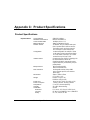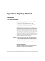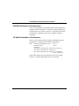
1
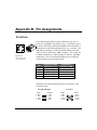
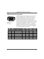
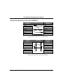
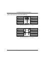
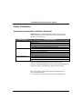
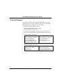
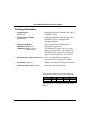
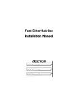
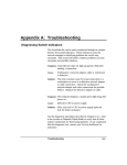
Appendix A: Troubleshooting Diagnosing Hub Indicators The Fast EtherHub 3500 Series can be easily monitored through its comprehensive panel indicators. These indicators assist the network manager in identifying problems the hub may encounter. This section describes common problems you may encounter and possible solutions. Symptom: Link indicator does not light up (green) after making a connection. Network interface (e.g., a network adapter card on the attached device), network cable, or hub port is defective. Solution: Verify that the hub and attached device are powered on. Be sure the cable is plugged into both the hub and corresponding device. Verify that the proper cable type is used and its length does not exceed specified limits (Chapter 2). Check the adapter on the attached device and cable connections for possible defects. Replace the defective adapter or cable if necessary. Cause: Symptom: Power indicator does not light up (green) after power on. Defective power outlet, power cord, or internal power supply. Solution: Check the power outlet by plugging in another device that is functioning properly. Check the power cord with another device. If these measures fail to resolve the problem, have the unit’s power supply replaced by a qualified Accton distributor. Cause: Use the diagnostic procedures described in Chapter 2 to verify that all other system components are functioning properly. If any component fails the diagnostic test, contact your Accton distributor for assistance. Troubleshooting A-1 Fast EtherHub 3500 System User’s Guide System Diagnostics Power and Cooling Problems If the power indicator does not turn on when the power cord is plugged in, you may have a problem with the power outlet, power cord, or internal power supply as explained in the previous section. However, if the unit powers off after running for a while, check for loose power connections, power losses or surges at the power outlet, and verify that the fans on back of the unit are unobstructed and running prior to shutdown. If you still cannot isolate the problem, then the internal power supply may be defective. In this case, contact your Accton distributor for assistance. Installation Verify that all system components have been properly installed. If one or more components appear to be malfunctioning (e.g., the power cord or network cabling), test them in an alternate environment where you are sure that all the other components are functioning properly. Transmission Mode If any devices are attached to the 100BASE-TX or FX SmartExtender Module, and operate at full duplex but do not support auto-negotiation, then you must manually set the transmission mode for this port on the hub. (Refer to Configuring Port Parameters in Chapter 5.) The default method of selecting the transmission mode for the 100BASE-TX and FX extender module is auto-negotiation. Therefore, if the Link signal is disrupted (e.g., by unplugging the network cable and plugging it back in again, or by resetting the power), the port will try to reestablish communications with the attached device via auto-negotiation. If auto-negotiation fails, A-2 Troubleshooting Fast EtherHub 3500 System User’s Guide then communications are set to half duplex by default. Based on this type of industry-standard connection policy, if you are using a full-duplex device that does not support auto-negotiation, communications can be easily lost (i.e., reset to the wrong mode) whenever the attached device is reset or experiences a power fluctuation. The best way to resolve this problem is to upgrade these devices to versions which support autonegotiation. Cabling 1. Verify that the cabling type is correct. Be sure all cable connectors are securely seated in the required ports. Use 100W cable for all twisted-pair connections to 100BASE-TX ports. Use Category 5 cable for all 100 Mbps Fast Ethernet connections; or use Category 3, 4 or 5 cable when making 10 Mbps Ethernet connections to the 100BASE-TX extender module. 2. Verify that the cabling type is correct. Be sure all cable connectors are securely seated in the required ports. Straight-through cable should be used for all standard twisted-pair connections. 3. When cascading two devices using RJ-45 station ports at both ends of the cable (i.e., not an MDI port), make sure a crossover cable is used. Crossover cable should only be used if the a daisy-chain port is not available. 4. Make sure all devices are connected to the network. Equipment may have been unintentionally disconnected from the network. External Adapters Make sure the network adapter cards installed in the workstations are compatible and are in good working condition. Troubleshooting A-3 Fast EtherHub 3500 System User’s Guide Physical Configuration If problems occur after altering the network configuration, restore the original connections, and try to track the problem down by implementing the new changes, one step at a time. Ensure that cable distances and other physical aspects of the installation do not exceed recommendations (Chapter 2). System Integrity As a last resort verify the hub’s integrity with a power-on reset. Turn the power to the hub off and then on several times. If the problem still persists and you have completed all the preceding diagnoses, then contact your Accton distributor for further assistance. (Refer to Appendix E.) A-4 Troubleshooting Appendix B: Pin Assignments RJ-45 Port Figure B-1 RJ-45 Connector (on the Hub Side) RJ-45 station ports (MDI-X) can be attached to any devices which use a standard LAN interface (e.g., a workstation, server or router). RJ-45 daisy-chain ports (MDI) can be cascaded to a station port on similar networking devices (e.g., a switch). Use unshielded twisted-pair (UTP) or shielded twisted-pair (STP) cable for RJ-45 connections: 100W Category 3, 4 or 5 cable for 10 Mbps connections or 100W Category 5 cable for 100 Mbps connections. Also be sure that the length of any twisted-pair connection does not exceed 100 meters. Pin 1 2 3 6 4,5,7,8 Assignment for MDI-X Station Ports 1 ~ 12 Input Receive Data + Input Receive Data Output Transmit Data + Output Transmit Data Not Used Assignment for Cascade Port 12MDI Output Transmit Data + Output Transmit Data Input Receive Data + Input Receive Data Not Used Table B.1 RJ-45 Pin Assignments Schematics for both straight and crossover twisted-pair cable are shown below. Straight-Through (Hub) 1 2 3 6 IRD+ IRDOTD+ OTD- (Adapter) 1 2 3 6 OTD+ OTDIRD+ IRD- Pin Assignments Crossover (Hub) 1 2 3 6 IRD+ IRDOTD+ OTD- (Hub) 1 2 3 6 IRD+ IRDOTD+ OTD- B-1 Fast EtherHub 3500 System User’s Guide DB9 Serial Port Pin Description The DB9 serial port on the front panel is used to connect the hub to a management device. The on-board menu-driven configuration program can be accessed from a terminal, a PC running a terminal emulation program, or from a remote location via a modem connection. In-band management software (which usually provides a graphical interface) can also be used to manage the hub from a remote location via a modem connection, by running SLIP over TCP/IP. You can use the managment port to configure port settings (e.g., enabled or disabled), or to update device firmware. The pin assignments used to connect various device types to the hub’s managment port are provided in the following tables. Figure B-2 DB9 Serial Port (on the Hub Side) EIA Circuit CF BB BA CD AB CC CA CB CE CCITT Signal 109 104 103 108.2 102 107 105 106 125 Hub’s DB9 DTE Pin # Description DCD (Data Carrier Detected) RxD (Received Data) TxD (Transmitted Data) DTR (Data Terminal Ready) SG (Signal Ground) DSR (Data Set Ready) RTS (Request-to-Send) CTS (Clear-to-Send) RI (Ring Indicator) 1 2 3 4 5 6 7 8 9 PC DB9 DTE Pin # 1 2 3 4 5 6 7 8 9 Table B.2 DB9 Port Pin Assignments B-2 Pin Assignments Modem DB25 DCE Pin # 8 3 2 20 7 6 4 5 22 Signal Direction DTE -DCE < -------< --------------- > -------- > ---------< --------------- > < -------< -------- Fast EtherHub 3500 System User’s Guide Hub’s 9-Pin Serial Port to PC's 9-Pin COM Port Hub’s 9-Pin Serial Port 1 DCD 2 RXD 3 TXD 4 DTR 5 SGND 6 DSR 7 RTS 8 CTS 9 RI Cable Wiring PC's 9-Pin COM Port 1 DCD 2 RXD 3 TXD 4 DTR 5 SGND 6 DSR 7 RTS 8 CTS 9 RI Table B.3 Full-Pin Connection from Hub’s 9-Pin Serial Port to PC's 9-Pin COM Port Hub’s 9-Pin Serial Port 1 DCD 2 RXD 3 TXD 4 DTR 5 SGND 6 DSR 7 RTS 8 CTS 9 RI Cable Wiring PC's 9-Pin COM Port 1 DCD 2 RXD 3 TXD 4 DTR 5 SGND 6 DSR 7 RTS 8 CTS 9 RI Table B.4 Three-Pin Connection from Hub’s 9-Pin Serial Port to PC's 9-Pin COM Port Pin Assignments B-3 Fast EtherHub 3500 System User’s Guide Hub’s 9-Pin Serial Port to PC's 25-Pin DTE Port Hub’s 9-Pin Serial Port 1 DCD 2 RXD 3 TXD 4 DTR 5 SGND 6 DSR 7 RTS 8 CTS 9 RI Cable Wiring PC’s 25-Pin DTE Port 4 RTS 3 TXD 2 RXD 6 DSR 7 SGND 20 DTR 5 CTS 8 DCD 22 RI Table B.5 Full-Pin Connection from Hub’s 9-Pin Serial Port to PC’s 25-Pin DTE Port Hub’s 9-Pin Serial Port 1 DCD 2 RXD 3 TXD 4 DTR 5 SGND 6 DSR 7 RTS 8 CTS 9 RI Cable Wiring PC’s 25-Pin DTE Port 4 RTS 3 TXD 2 RXD 6 DSR 7 SGND 20 DTR 5 CTS 8 DCD 22 RI Table B.6 Three-Pin Connection from Hub’s 9-Pin Serial Port to PC’s 25-Pin DTE Port B-4 Pin Assignments Fast EtherHub 3500 System User’s Guide Hub’s 9-Pin Serial Port to Modem's 25-Pin DCE Port Hub’s 9-Pin Serial Port 1 2 3 4 5 6 7 8 9 Modem's 25-Pin DCE Port < ---------- DCD ---------< ---------- RXD --------------------- TXD -------- > ------------ DTR -------- > ----------- SGND --------< ---------- DSR --------------------- RTS -------- > < --------- CTS ----------< ----------- RI ------------ 8 3 2 20 7 6 4 5 22 Table B.7 Hub’s 9-Pin Serial Port to Modem's 25-Pin DCE Port Pin Assignments Pin Assignments B-5 Appendix C: Product Specifications Product Specifications Repeater Board Access Method Standards Conformance Communication Rate Media Supported Number of Ports Configuration Indicator Panel Microprocessor Fault Tolerance Dimensions Weight Power Input Power Consumption Temperature Humidity Certification Emissions Immunity Safety Product Specifications CSMA/CD, 100 Mbps IEEE 802.3u 100BASE-TX 100 Mbps on Ports 1 - 12 100WCat 5 twisted-pair (2-pair) 12 100BASE-TX RJ-45 shielded station ports (Port 12 provides MDI-X or MDI connection); 2 backplane ports for stack interconnection; and 1 serial port for system management On-board configuration via serial port or Telnet; or with optional in-band management software via a local network connection or via a remote modem link using SLIP over TCP/IP Comprehensive array of LEDs for displaying hub ID, network utilization, collision rate, SmartExtender Module, management agents, segment attachment, port link/activity, and port partition/disable 8031 (Fast EtherHub-12i); i960 (Fast EtherHub-12mi) Hot swappable modules; backup SNMP agent; redundant port links; and redundant power supply 440mm x 320mm x 65mm (17.3[ x 12.6[ x 2.6[) EH3512i: 6.2 kg (13.7 lb); EH3512mi: 6.6 kg (14.6 lb) 100 to 240 VAC (10%), 50 to 60 Hz ( 3%) 1.0 Amp @ 100VAC, 0.8 Amp @ 230VAC 5°C to 40°C (Standard Operating) 5% to 85% (Noncondensing) CE Mark FCC Class A, VCCI Class A, CISPR Class A IEC 801-2,3,4,6, EN60555-2 Class A, EN60555-3 UL, CSA, TÜV/GS, IEC 950 C-1 Fast EtherHub 3500 System User’s Guide Repeater Stack Expansion Expansion Interface Configuration Segmentation Up to 6 modules (72 station ports) FlexBus 3500 stack cable (68 wires) Automatic hub-ID and bus termination Supports 3 or more segments in a stack Extender Port Access Method Standards Conformance Communication Rate Communication Mode CSMA/CD, 10 Mbps or 100 Mbps IEEE 802.3u 100BASE-TX, FX 10 or 100 Mbps (via auto-detection) Full or half duplex for 100BASE-TX & FX (via auto-negotiation) 100BASE-TX 100Wtwisted-pair (2-pair); Cat 5 for 100 Mbps, or Cat 3,4,5 for 10 Mbps 100BASE-FX 50/125 mm or 62.5/125 mm multimode fiber 1 100BASE-TX RJ-45 port or 1 100BASE-FX SC or ST type port (TX provides MDI-X or MDI connection) Comprehensive array of LEDs for displaying port link, collision, activity, transmission speed, transmission mode Media Supported Number of Ports Indicator Panel Switching Criteria Network Bridging Function Switching Method Maximum Filtering Rate Maximum Forwarding Rate Network Latency Address Table Queue Buffer C-2 Product Specifications filtering, forwarding and learning adaptive cut-through: fragment-free or store-and-forward line speed line speed less than 20 microseconds 4K entries/port 160K bytes Appendix D: Regulatory Standards EMI Warning FCC Class A Certification This device complies with Part 15 of the FCC Rules. Operation is subject to the following conditions: 1. This device may not cause harmful interference, and 2. This device must accept any interference received,including interference that may cause undesired operation. Warning: This equipment generates, uses, and can radiate radio frequency energy and, if not installed and used in accordance with the instruction manual, may cause interference to radio communications. It has been tested and found to comply with the limits for a Class A digital device pursuant to Subpart B of Part 15 of FCC Rules, which are designed to provide reasonable protection against such interference when operated in a commercial environment. Operation of this equipment in a residential area is likely to cause interference, in which case the user, at his own expense, will be required to take whatever measures are required to correct the interference. Warnings 1. Wear an anti-static wrist strap or take other suitable measures to prevent electrostatic discharge whenever handling this equipment. 2. When connecting this hub to a power outlet, connect the field ground lead on the tri-pole power plug to a valid earth ground line to prevent electrical hazards. You may find the following booklet prepared by the Federal Communications Commission helpful: The Interference Handbook This booklet is available from the U.S. Government Printing Office. Washington, D.C. 20402. Stock No. 004-000-00345-4. Regulatory Standards D-1 Fast EtherHub 3500 System User’s Guide Note: In order to maintain compliance with the limits of a Class A digital device, Accton requires that you use a quality interface cable when connecting to this device. Changes or modifications not expressly approved by Accton could void the user’s authority to operate this equipment. Suggested cable type is: • 100WSTP/UTP for RJ-45 connections: 100BASE-TX (10BASE-T) • 50/125 or 62.5/125 mm multi-mode cable for fiber optic connections: 100BASE-FX Voluntary Control Council for Interference (VCCI-A) This product also complies with CISPR22 Class A (EN55022 Class A). D-2 Regulatory Standards Fast EtherHub 3500 System User’s Guide EN55022 Declaration of Conformance This is to certify that the Accton Ethernet Hub is shielded against the generation of radio interference in accordance with the application of Council Directive 89/336/EEC, Article 4a. Conformity is declared by the application of EN55022:1987 Class A (CISPR 22:1985/BS 6527:1988). CE Mark Declaration of Conformance This is to certify that this product complies with ISO/IEC Guide 22 and EN45014. It conforms to the following specifications: EMC: EN55022(1988)/CISPR-22(1985) class A EN60555-2(1995) class A EN60555-3 IEC 1000-4-2(1995)/IEC 801-2(1991) 4kV CD, 8kV AD IEC 1000-4-3(1995)/IEC 801-3(1984) 3V/m IEC 1000-4-4(1995)/IEC 801-4(1988) 1kV - (power line) 0.5kV - (signal line) This product complies with the requirements of the Low Voltage Directive 73/23/EEC and the EMC Directive 89/336/EEC. Regulatory Standards D-3 Fast EtherHub 3500 System User’s Guide Safety Compliance Underwriters Laboratories Compliance Statement Important! Before making connections, make sure you have the correct Cord Set. Check it (read the label on the cable) against the following specification list. Operating Voltage 120 Volts 240 Volts (For North America) 240 Volts (For Europe only) Cord Set Specifications UL Listed/CSA Certified Cord Set Minimum 18 AWG Type SVT or SJT three conductor cord Maximum length of 15 feet Parallel blade, grounding type attachment plug rated 15A, 125V UL Listed/CSA Certified Cord Set Minimum 18 AWG Type SVT or SJT three conductor cord Maximum length of 15 feet Tandem blade, grounding type attachment plug rated 15A, 125V Cord Set with H05VV-F cord having three conductors with minimum diameter of 0.75 mm2 IEC-320 receptacle Male plug rated 6A, 250V The unit automatically matches the connected input voltage. Therefore, no additional adjustments are necessary when connecting it to any input voltage within the range marked on the rear panel. Do not plug a phone jack connector into any of the RJ-45 ports. This may damage the hub. Les raccordeurs ne sont pas utilisé pour le système téléphonique! D-4 Regulatory Standards Fast EtherHub 3500 System User’s Guide Sicherheitshinweise 1. Die Steckdose muß sich in der Nähe des Gerätes befinden und leicht zugänglich sein. 2. Zum Reinigen den Stecker aus der Steckdose ziehen. Beim Reinigen keine Flüssigreiniger oder Sprays verwenden, sondern ein angefeuchtetes Tuch. 3. Das produkt gerät nicht in Naßräume oder in der Nähe von Wasser benutzen, wie z.B. Badezimmer, Schwimmbad, Spülbecken usw. . Das Eindringen von Wasser kann zur Zerstörung des Gerätes führen. 4. Das produkt gerät nicht auf einer unstabilen Unterlage, wie z.B. Rollwagen, Gestell usw., aufstellen. Es könnte herunterfallen und Verletzungen oder Beschädigungen von Mensch und Gerät verursachen. 5. Die Belüftungsöffnungen nicht blockieren oder auf falscher Oberfläche, wie Bett, Sofa usw., stellen. Durch die Blockierung kann es zur Zerstörung des Gerätes durch Überhitzung kommen. 6. Versuchen Sie niemals dieses Gerät selbst zu warten, da beim Öffnen oder Abnehmen des Gehäuses die Gefahr eines elektrischen Schlages besteht. 7. Keine Gegenstände auf das Anschlußkabel stellen, damit es nicht durch scharfe Kanten zerstört werden kann. 8. Keinerlei Gegenstände durch die Öffungen in das Gerät stecken, da es dadurch sonst zu Kurzschlässen kommen kann. 9. Bei Störungen des Gerätes den Wartungsdienst verständigen. 10. Bei Reperaturen dürfen nur Orginalersatzteile oder Bauteile mit gleichen Eigenschaften verwendet werden. Andere Bauteile können Feuer, elektrischen Schlag oder andere Gefahren verursachen. 11. Nach Beendigung von Wartungsarbeiten oder Reperaturen durch den Kundendienst sollte die Sicherheitsprüfung durchgeführt werden. 12. Bei längerem Stillstand des Gerätes, ist diese von der Versorgungsspannung zu trennen. Dies verhindert eine Beschädigung des Gerätes durch eine Überspannung in der Zuleitung. 13. Der arbeitsplatzbezogene Lärmschutzpegel nach DIN 45 635 ist kleiner 70dB (A). Regulatory Standards D-5 Appendix E: Product Support Services Product Registration Fill in the Owner Registration Card and mail it to Accton Technology Corporation. Accton will keep your record and inform you of any new Accton unit developments. Problem Report If problems occur during unit operation, please check the adapter configuration settings, cables, connectors, network terminators, hardware compatibility and other network components. Write a description of the problem, including what problems occurred, when they occurred, duration of the problems, the unit number, serial number, hardware, software and the DOS version that you are using. Then contact your dealer or Accton Technology Corporation for assistance. Hardware Repair Service You must get an RMA (Return Materials Authorization) number before returning any hardware for repair. To obtain this number please inform Accton of your company name, address, unit name and model number, contact person, telephone number, and a problem description list. If your unit is under repair warranty you must also give your purchase date. Carefully pack your hardware. If possible, use the original carton. Mark the RMA number on the carton and send it to your dealer. After repair, Accton will inform you of the date of delivery and the exact amount due. Please send the payment by T/T (Telegram Transfer), and Accton will send you the fixed component after receiving payment. With or without warranty, if the hardware is found to be free of defects, you will only be charged for testing and handling. Product Support Services E-1 Fast EtherHub 3500 System User’s Guide Software Update and Upgrade Service Accton constantly improves its software units by adding enhancements and new features. Minor software updates are free of charge. If greater changes have been made to the software, Accton offers software upgrade services at a specially reduced price. Bulletin Board Service (BBS) • In countries other than the U.S., call 886-3-5770-654 to reach Accton Taiwan’s modem line. Modems with 14400 through 2400 baud are supported. Choose 8 data bits, 1 stop bit and no parity. Standard VT100 terminal emulation is supported • In the United States, call 408-452-8828 to reach the Accton USA’s BBS line. Modems with 14400 through 2400 baud are supported. Choose 8 data bits, 1 stop bit and no parity. Standard VT100 terminal emulation is supported. Interactive Fast fax (U.S.A. office) Printed technical documentation can be sent to your fax machine, 24hours a day. • E-2 Call 408-452-8811 to reach Accton’s interactive Fast fax service. You will need a Touch-Tone phone and a fax machine (or equivalent). Choose document 911 for a listing of technical bulletins. Product Support Services Fast EtherHub 3500 System User’s Guide Technical Support Your dealer or installer is the person who understands your network and Accton units. If neither is available to help you, Accton technical support engineers are available by fax, mail or phone. • Send your technical questions by fax to: International Headquarters: 886-3-5770-267 USA Headquarters: 408-452-8988 • To obtain software upgrades connect via ftp to ftp.accton.com.tw • Send your technical questions by email to [email protected] • Mail your technical questions to: International Headquarters Accton Technology Corporation Attn: Technical Support No. 1 Creation Road III Science-based Industrial Park Hsinchu 300, Taiwan, R.O.C. USA Headquarters Accton Technology Corporation Attn: Technical Support 1962 Zanker Road, San Jose, CA 95112, U.S.A. During local business hours, call: International Headquarters (Monday through Friday, 8 am to 6 p.m.): 886-3-5770-270 Product Support Services USA Headquarters (Monday through Friday, 7 am to 5 p.m. Pacific Time): 408-452-8900 or 800-926-9288 E-3 Fast EtherHub 3500 System User’s Guide Limited Warranty Accton warrants to the original owner that the product delivered in this package will be free from defects in material and workmanship for the lifetime of the product. For the warranty to apply, you must register your purchase by returning the registration card indicating the date of purchase and including proof of purchase. There will be a minimal charge to replace consumable components, such as fuses, power transformers, and mechanical cooling devices. The warranty does not cover the product if it is damaged in the process of being installed. Accton recommends that you have the company from whom you purchased this product install it. THE ABOVE WARRANTY IS IN LIEU OF ANY OTHER WARRANTY, WHETHER EXPRESS, IMPLIED OR STATUTORY, INCLUDING BUT NOT LIMITED TO ANY WARRANTY OF MERCHANTABILITY, FITNESS FOR A PARTICULAR PURPOSE, OR ANY WARRANTY ARISING OUT OF ANY PROPOSAL, SPECIFICATION OR SAMPLE. ACCTON SHALL NOT BE LIABLE FOR INCIDENTAL OR CONSEQUENTIAL DAMAGES. ACCTON NEITHER ASSUMES NOR AUTHORIZES ANY PERSON TO ASSUME FOR IT ANY OTHER LIABILITY. Customer Remedies If the product is found to be defective within the first two years from the later of date of purchase or date of manufacture, Accton’s entire liability and your exclusive remedy for any breach of warranty, shall be, at its option, to repair or replace the product at no charge except as set forth below. If the product is found to be defective after two years from the later of date of purchase or date of manufacture, Accton will charge a process and handling fee, provided that you deliver the product along with a return material authorization (RMA) number either to the company from whom you purchased it or to Accton. Accton warrants the repaired or replaced product to be free from defects in material and workmanship for the remainder of the original product’s warranty period. Consumable components are warranted only for two years. E-4 Product Support Services Fast EtherHub 3500 System User’s Guide Return Process Before you may return any Accton product to Accton, you must request an RMA number by calling, faxing or writing Accton’s Service Department at the address listed below. If you ship the product, you must assume the risk of damage or loss in transit. You must use the original container (or the equivalent) and pay the shipping charge. Accton may replace or repair the product with either a new or reconditioned product, and the returned product becomes Accton’s property. At Accton’s sole discretion, Accton will issue a credit for either a comparable replacement Accton product or credit the original purchase price towards the purchase of any Accton product for any unrepairable, defective product. This warranty does not cover replacement of products damaged by abuse, accident, misuse, neglect, alteration, repair, disaster, improper installation or improper testing. ACCTON SHALL NOT BE HELD LIABLE FOR ANY LOSS OF PROFITS, LOSS OF USE, INCIDENTAL, CONSEQUENTIAL OR SPECIAL DAMAGES CAUSED BY THE USE OF THIS PRODUCT OR INABILITY TO USE IT, EVEN IF THE COMPANY OR ACCTON HAS BEEN ADVISED OF SUCH LIABILITY OR OTHER SPECIAL CLAIMS. If you purchased this product in the USA, be aware that some states do not allow limitations on how long an implied warranty lasts, so the above limitations may not apply to you. Some states do not allow the exclusion or limitation of incidental or consequential damages, so the above limitations or exclusions may not apply to you. This warranty gives you specific legal rights and you may have other rights which vary from state to state. All parts or components contained in this product are covered by Accton’s Limited Lifetime Warranty for this product. The product may contain fully tested, recycled parts, warranted as if new. For warranty information: All territories except North and South America: Accton Technology Corporation, International Headquarters No. 1, Creation Rd. III, Science-based Industrial Park, Hsinchu 300, Taiwan, R.O.C. Phone: 886-3-5770-270 fax: 886-3-5770-267 BBS: 886-3-5770-654 North and South America: Accton Technology Corporation, USA Headquarters 1962 Zanker Road, San Jose, CA 95112, U.S.A. Phone: 408-452-8900 fax: 408-452-8988 BBS: 408-452-8828 Product Support Services E-5 Fast EtherHub 3500 System User’s Guide Accton Offices Accton Australia, Unit 23, No.27 Doomben Ave., Eastwood, N.S.W. 2122, Australia Phone: 612-8582436 fax: 612-8581723 Accton Technology Corporation International Headquarters, No. 1 Creation Rd. III, Science-based Industrial Park, Hsinchu 300, Taiwan, R.O.C. Hsinchu: Phone: 886-3-5770-270, fax: 886-3-5770-267, 886-3-5775-541 BBS: 886-3-5770-654 Taipei: Phone: 886-2-577-1220 to 9 fax: 886-2-577-0816 Accton Deutschland, Bahnhofstr. 6, 65623 Hahnstatten, Germany Phone: 49-64-30-22-17 fax: 49-64-30-22-70 Accton USA, 1962 Zanker Road, San Jose, CA 95112, USA Phone: 408-452-8900, 408-452-8080 fax: 408-452-8988 BBS: 408-452-8828 FAST fax: 408-452-8811 Accton UK, The Mill Horton Road, Stanwell Moor, Staines. Middx. TW19 6BJ United Kingdom Phone: 44-1753-687677, 44-1753-680109 fax: 44-1753-689010 E-6 Accton Japan, Kano Bldg. 7F, 1-25-1 Nishi-Gotanda, Shinagawa-ku, 141 Tokyo, Japan Phone: 81-3-3495-1351 fax: 81-3-3495-1352 Product Support Services Fast EtherHub 3500 System User’s Guide Ordering Information • Fast EtherHub-12i Intelligent Fast Ethernet Stackable Hub with 12 100BASE-TX Ports (EH3512I-TX) • Fast EtherHub-12mi SNMP (EH3512M-TX) Intelligent Fast Ethernet Stackable Hub with 12 100BASE-TX Ports; including SNMP Managment Support • SmartExtender Modules Slide in module with 1 100BASE-TX or 100BASE-FX Uplink Port The 100BASE-TX module runs at 10 or 100 Mbps (via auto-detection). The 100BASE-TX and 100BASE-FX modules run at half or full duplex (via auto-negotiation). See Table E-1. 100BASE-TX (EM3551-TX) 100BASE-FX (EM3551-FX-SC or EM3551-FX-ST) • Redundant Power Supply (EM3550-PWR) Serves as a redundant power supply or a replacement for the primary power supply. • AccView/Open (SW6102) Windows-based network management software. • FlexBus 3500 Stack Cable (EC3550) 20cm stack cable with connectors The operational parameters supported by the different SmartExtender modules are shown in the following table. Module 100BASE-TX 100BASE-FX 10 Mbps 100 Mbps [ [ [ Half Dulex Full Duplex [ [ [ [ Table Appendix E:.1 Parameters for SmartExtender Modules Product Support Services E-7 Glossary 10BASE-T IEEE’s specifications for running 10 Mbps Ethernet using twisted-pair cable (100W STP or UTP). The maximum length of cable for a point-to-point connection is 100 meters, and the maximum number of nodes is 1024. 100BASE-TX IEEE’s specifications for 100 Mbps Ethernet using 2-pairs of Category 5 twisted-pair cable. The Fast EtherHub 3500 models require 100W STP or UTP cable. The maximum length of cable for a point-topoint connection is 100 meters, and the maximum number of nodes is 1024. 100BASE-FX IEEE’s specifications for 100 Mbps Ethernet using multimode fiber optic cable. The 100BASE-FX SmartExtender Module must be used to support fiber optic cable with SC or ST type connectors. The maximum length for a point-to-point connection is 2 kilometers at full duplex, or 412 meters at half duplex. AccView/Open AccView/Open is a complete network management product with modules for managing Accton devices. BOOTP Boostrap protocol used to load the operating system for devices connected to the network. Collision A condition in which two packets transmitted over a medium interfere with each other. Their interference makes both signals unintelligible. The transmitting devices have to halt transmission for a random period of time before trying to send data again. Note that collisions do not occur on fullduplex connections. Configuration The way to set up a computer, server, or local area network. Glossary 1 Fast EtherHub 3500 System User’s Guide Connection A logical binding between two or more users of an interconnection service. Daisy-Chain Port An MDI RJ-45 port used to cascade compatible devices in a daisy-chain configuration using straightthrough twisted-pair cable. To cascade two devices, either run a connection from the daisy-chain port on one device to a station port on the other device, or cascade the two devices by running crossover cable between MDI-X station ports on both devices. Remember that this is a Class I Fast Ethernet Repeater and cannot be cascaded to another device in the same collision domain. Ethernet A network communication system developed and standardized by DEC, Intel, and Xerox, using baseband transmission, CSMA/CD access, logical bus topology, and coaxial cable. The successor IEEE 802.3 standard provides for integration into the OSI model and extends the physical layer and media with repeaters and implementations that operate on fiber optics, broadband, and twisted-pair. Fast Ethernet 100 Mbps network communication system based on Ethernet and the CSMA/CD access method. Fast EtherHub 3500 System Accton’s Fast Ethernet enhancement and management products. Each component in the system carries a multi-segment bus architecture that enhances traffic management and network bandwidth utilization. File Transfer Protocol (FTP) An application protocol used for transferring files to network devices. FlexBus Ports SCSI ports found at the backplane of the EtherHub labeled In and Out. These ports are used for linking the hub to other compatible hubs using Accton’s FlexBus 3500 cable. IEEE 802.3 Standard Standard for the physical and electrical connections in local area networks developed by the IEEE (Institute of Electrical and Electronics Engineers). The IEEE 802.3u standard covers these same issues for 100 Mbps networks. 2 Glossary Fast EtherHub 3500 System User’s Guide In-Band A way of communicating with a network device via a local network connection. Jabber Refers to an abnormal Ethernet frame transmission. The frames causing jabber are normally much too long. It may come from a malfunctioning Ethernet card and may cause data loss for all network users. LED Light emitting diode on the front panel of the EtherHub used for monitoring a hub or network condition. MAC (Media Access Control) A portion of the networking protocol that governs access to the transmission medium, facilitating the exchange of data between network nodes. MDI Port (Medium Dependent Interface) MDI is the IEEE standard for the twisted-pair interface to 10BASE-T (or 100BASE-TX) . This RJ-45 port can be used with straight-through cable to connect the hub to a network interconnection device, such a switch. Pin-out assignments are shown in Appendix B. MDI-X Port (Medium Dependent Interface - Crossed) This RJ-45 port, which crosses the receive and transmit signals internally, can be used with straightthrough cable to connect the switch to any device that has a standard network interface (e.g., workstation, server or router). Pin-out assignments are shown in Appendix B. MIB (Management Information Base) An acronym for Management Information Base. It is a set of database objects that contains information about the device. MII (Media Independent Interface) IEEE’s specifications for a multi-media interface that supports 100BASE-TX, 100BASE-FX or 10BASE-T. Glossary 3 Fast EtherHub 3500 System User’s Guide Multi-Segment Architecture Type of architecture that enhances traffic management and network bandwidth utilization by segregating network traffic. Network Management Station The computer used to run SNMP management software (e.g., AccView/Open). It is used by the network manager to monitor the network. Out-of-Band A way of communicating with a network device from outside the standard network channels. RJ-45 Connector Most common terminator for twisted-pair wiring. SLIP (Serial Line Internet Protocol) Internet protocol used to transfer IP datagrams over serial lines. SNMP (Simple Network Management Protocol) The application protocol offering network management services in the Internet suit of protocols. Star Topology Physical connections for RJ-45 ports are limited to a star configuration (i.e., similar to a hub and spoke arrangement). This topology also requires that only one path exists between any two nodes, and that data transmitted by any node is concurrently available to all other nodes within the same local network (i.e., immediate collision domain). Station Port (MDI-X) MDI-X ports which are used for connecting the hub to any workstation or server that has a properly installed network adapter card. (For port 12, the selector switch must be set to MDI-X.) 4 Glossary Fast EtherHub 3500 System User’s Guide STP (Shielded Twisted-Pair) 100W Category 5 twisted-pair wire covered with an external aluminum-foil or woven-copper shield designed to reduce excessive noise pick up or radiation. The STP cable refered to in this manual is also sometimes called screened twisted-pair (ScTP). Its impedance is 100Wand has the same pin assignment as UTP. This cable should not be confused with the older 150Wcable type designed by IBM. UTP (Unshielded Twisted-Pair) Cable composed of insulated wires twisted together to reduce electrical interference. Xmodem A protocol used to transfer files between devices. Data is grouped in 128-bytes blocks and errorcorrected. Glossary 5 Index A Accessing the Configuration Management Program • 4-5 AccView/Open • 1-4 Applications Attaching the Stack to Multiple Segments • 3-6 Attaching the Stack to One Segment • 3-5 Connecting Remote Stacks • 3-12 Connecting to the Network Backbone • 3-15 Extending the Network with Alternate Connections • 3-9 Interconnecting the Segments • 3-11 Isolating Each Hub • 3-8 Isolating Specific Hub Connections • 3-7 Linking a Stack to a Network Management Station • 3-10 Operating in Novell NetWare IPX Environment • 3-13 Operating in TCP/IP Environment • 3-14 B Backup Port Parameters • 4-29 Bridging Functions • 2-10 Bytes • 4-37, 4-39 C Collision • 5-8 Communication Mode Selection • 2-10 Setting • 2-10 Configuration Parameters Authorized Port Address • 4-31 Bootup Option • 4-23 Community Name • 4-16 Download Filename • 4-33 Download Mode • 4-33 Download Server IP • 4-33 Gateway IP • 4-20 Half/Full Duplex • 4-28 Hub ID • 4-23 Hub Position • 4-23 IPX Frame Type • 4-20 Link State • 4-26, 4-28 Partition • 4-26 Segment Assignment • 4-23 Serial IP • 4-20 Subnet Mask • 4-20 Transmission Speed • 4-28 Upload Mode • 4-34 User Type • 4-35 Configuration Program Fast EtherHub-12i • 4-8 Fast EtherHub-12mi • 4-11 Stack • 4-11 Configuring the System • 4-1 Configuring with the On-board Program • 4-5 Connecting Fiber-optic Cabling • 2-8 Connecting the Hub System • 2-4 Connecting to MDI Daisy-chain Port • 2-6 Connecting to MDI-X Station Port • 2-4 Connecting to SmartExtender Module • 2-6 Connecting to the Stack’s Backplane • 2-5 Connecting Twisted-pair Cabling • 2-7 Console Lockout • 4-36 Console Port • see Serial Port Cut-through Switching • 1-9 D Daisy-chain Port • 5-13 Diagnostic Tests • 2-12 Disable • 5-10 Distance Limit and Power Loss in Fiber Optics • 2-8 Downloading System Software TFTP Server • 4-32 Xmodem Protocol • 4-34 Index 1 Fast EtherHub 3500 System User’s Guide Isolation • 5-7 Link • 5-3 Link/Activity • 5-10 Management Agents • 5-5 Master • 5-5 Partition/Disable • 5-9 Port Status • 5-10 Power • 5-2 Rx • 5-3 Segment • 5-4 Serial • 5-6 SmartExtender Module • 5-2 SNMP • 5-4 Terminator • 5-7 Tx • 5-3 Utilization • 5-7 Installation Mounting Hubs in a Rack • 2-3 Stacking Hubs without a Rack • 2-2 Installing a Backup Power Supply • 2-11 Installing a SmartExtender Module • 2-7 Installing an SNMP Backup Agent • 2-14 Installing the System • 2-1 Interhub • 5-3 Internal Management Module • 1-4 IP Trap Managers • 4-17 IPX Trap Managers • 4-18 E EMI Warning • D-1 F Fast EtherHub 3500 • 1-1 Fast EtherHub-12i • 1-2 Fast EtherHub-12mi SNMP • 1-3 FCC Warning • D-1 Filtering Packets • 1-9 Flash ROM • 4-33 FlexBus 3500 Management Link • 3-2 FlexBus 3500 Ports • 5-16 Stack In • 5-16 Stack Out • 5-16 Forwarding Packets • 1-9 H Hardware Installation • 2-1 Hardware Reference • 5-1 Hot Remove Function • 2-13 Hub Configuration • 4-21 Hub ID Configuration • 4-24 Hub ID Setting • 3-2 Hub IDs • 5-5 Hub Security • 4-30 Hub Statistics • 4-38 L LEDs (see Indicators) Limited Warranty • E-4 Link • 5-11 Link Indicator • 2-15 I Indicator Panel • 5-2 Indicators 100 • 5-3 Backup • 5-5 Collision • 5-3, 5-8 Diagnostic Test Indicators • 5-11 FDX • 5-3 Hub ID • 5-5 Interhub • 5-3 2 M Management Agents • 3-2 Management Ports (see FlexBus Ports) Index Fast EtherHub 3500 System User’s Guide Maximum Segment Length • 2-9 Multi-segment Architecture • 3-1 Multiple Agents • 3-3 N Network Connection MDI Daisy-chain Port • 2-6 MDI-X Station Port • 2-4 Verifying • 2-15 Network Connections • 5-13 Network Managment Software • 1-4 O On-board Configuration Program Configuring the Remote Site • 4-4 Remote Configuration Methods • 4-4 Remote Out-of-band Connection • 4-4 Setting Communication Parameters • 4-4 Ordering Information • E-7 P Package Contents • i Partition • 4-26, 5-9 Passwords Changing • 4-35 Pin Assignments Crossover Cable • B-1 Hub’s 9-Pin Serial Port to Modem's 25-Pin DCE Port • B-3 Hub’s 9-Pin Serial Port to PC's 25-Pin DTE Port • B-4 Hub’s 9-Pin Serial Port to PC's 9-Pin COM Port • B-3 RJ-45 Port • B-1 Serial Port • B-2 Port Attachment 10BASE-FX • 2-7 10BASE-T • 2-7 10BASE-TX • 2-7 Port Backup • 3-4 Port Intrusion Control • 4-30 Index Port Parameters • 4-26 Port Statistics • 4-39 Port Status Verifying • 2-15 Ports FlexBus • 5-16 Management Port • 5-14 MDI • 5-13 MDI-X • 5-13 Serial Port • 5-14 Power Module • 1-4 Power Supply Modules • 5-15 Powering on the Hub • 2-12 Pre-Installation Requirements • 2-1 Product Features • 1-5, 1-6 Product Specifications • C-1 Extender Port • C-2 Repeater Board • C-1 Repeater Stack • C-2 Switching Criteria • C-2 Product Support Services • E-1 Bulletin Board Service • E-2 Hardware Repair Service • E-1 Interactive Fast Fax • E-3 Software Update and Upgrade Service • E-2 Technical Support • E-3 Q Quick Installation • iii R Rear Panel • 5-15 Remote Configuration Methods Remote In-band • 4-5 Remote On-board • 4-4 Restarting the Agent • 4-13 3 Fast EtherHub 3500 System User’s Guide Collisions • 4-37, 4-39, 4-41 CRC Errors • 4-37, 4-39 Data Rate Mismatch • 4-41 FCS Errors • 4-41 Frames • 4-37, 4-39 Frames Too Long • 4-41 Late Events • 4-41 Runts • 4-41 Short Events • 4-41 Symbol Errors • 4-37, 4-39 Total Errors • 4-37, 4-39, 4-41 S Safety Compliance • D-4 Sample Network Configurations • 3-5 Security Features Intrusion Protection • 3-4 Segment Configuration • 4-19 Segment Statistics • 4-37 Segments Interconnecting • 2-11 Serial Port • 5-6, 5-14 Setting Up Network Connections • 3-1 SmartExtender Module • 1-3, 1-9 Parameters • 4-27 SNMP Agent • 4-15 SNMP Backup Agent • 3-3 SNMP Communities • 4-16 Stack Termination • 5-7 Station Ports • 5-13 Statistics Hub • 4-38 Port • 4-39 Repeater Ports • 4-40 Segment • 4-37 SmartExtender Module • 4-42 Switching Functions • 2-10 Switching Methods • 1-10 Switching Technology • 1-9 System Information • 4-14 System Configuration Setting Up Connections for • 4-1 System Configuration Options Direct Connection • 4-2 Local In-band Network Connection • 4-3 Local In-band Telnet Connection • 4-3 Network Connection • 4-2 Remote Connection • 4-4 System Operation Verifying • 2-15 System Statistics Allignment Errors • 4-37, 4-39, 4-41 Auto Partitions • 4-41 4 T Total Bandwidth • 1-6 Traffic • 5-11 Transmission Mode Selection • 2-10 Troubleshooting • 5-11, A-1 Cabling • A-3 Configuration • A-4 Hub Indicators • A-1 Installation • A-2 Power and Cooling • A-2 Twisted-pair Cable Category 3,4,5 • 2-4, A-3 U Using the System Configuration Program • 4-7 Utilization • 5-7 Index EH3512I-TX EH3512M-TX E0997-R03 150136-101