1
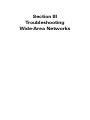
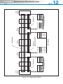
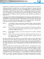
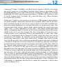
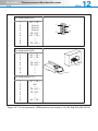
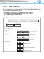
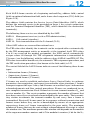
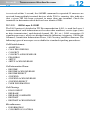
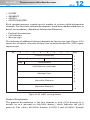
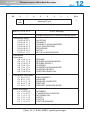
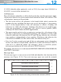
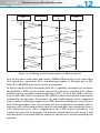
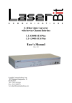
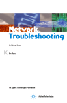
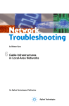
Network Troubleshooting by Othmar Kyas 12 ISDN An Agilent Technologies Publication Agilent Technologies Section III Troubleshooting Wide-Area Networks 12 ISDN “Experience is the worst teacher. It always gives you the exam first and the lesson afterwards.” UNKNOWN 12.1 ISDN: Specification and Implementation Integrated Services Digital Network, or ISDN, was the first communications infrastructure designed for transmission of both voice and data. The transmission technique is based on 64-Kbit/s bearer channels (B channels) and out-ofband signaling channels (D channels). There are two distinct types of network access in ISDN, each with different bandwidth capacities: basic rate access provides an access rate of up to 128 Kbit/s over two B channels and unused bandwidth in the D channel of up to 16 Kbit/s; primary rate access provides access rates of up to 1,536 Kbit/s in North America (23 B channels and one D channel) or up to 1,984 Kbit/s in Europe (30 B channels and one D channel). 2 B + D B a s ic - r a te in te r fa c e ( B R I) D ( 1 6 K b it/s ) B 1 , B 2 ( 6 4 K b it/s ) P r im a r y - r a te in te r fa c e ( P R I) D ( 6 4 K b it/s ) B 1 - B 2 3 ( 2 3 · 6 4 K b it/s ) o r B 1 - B 3 0 ( 3 0 · 6 4 K b it/s ) Figure 12.1: ISDN basic rate and primary rate access SECTION III TROUBLESHOOTING WIDE-AREA NETWORKS 436 ISDN 12 From today’s standpoint, the major drawbacks of ISDN are the limitation of the data speed to a maximum of 1,536 or 1,984 Kbit/s, which cannot be incrementally expanded, and the synchronous structure of the transmission channels, which does not permit dynamic allocation of bandwidth within the network. The latter characteristic was one of the reasons for the development of Frame Relay, a dedicated data transmission service that dynamically adjusts the bandwidth in use for more efficient data transfer. However, ISDN has the advantage of being an established international standard, providing a uniform digital interface for voice and data transmission worldwide. 12.1.1 ISDN Interface Reference Model C o m m o n IS D N In te rfa c e s C u s to m e r P r e m is e s T E 1 T E 2 C e n tr a l o ffic e N T -1 L T E T T A R S /T U U S a n d T In te r fa c e E x p a n d e d D e ta il T E 1 N T -2 T A S N T -1 T Figure 12.2 ISDN interface reference model • Exchange termination (ET) and line termination (LT) comprise the Central Office interface, called the V-Interface. • In North America, the U reference point is the standard interface and demarcation line between the network and the customer premises equipment (CPE). Outside North America the send (S)/transmit (T) reference point represents the border line between the CPE and the network. For the basic rate access the U-Interface is a 2-wire 2B1Q-coded line from the Central Office, for primary rate access the U-Interface consists of a 4-wire T1 (Digi- SECTION III TROUBLESHOOTING WIDE-AREA NETWORKS 437 • • • • • • ISDN 12 tal Speech 1nterpolation or DSI) in North America or an E1 outside North America. In Germany the U-Interface for primary rate is often referred to as a S2M interface. NT-1 is a network termination unit that converts the 2-wire 2B1Q line code into a 4-wire code used on the S and T interfaces. Most equipment used in North America will not have an S or T interface connector. NT-2 is a network termination unit that is ISDN-capable at both sides of the unit. A good example is an ISDN PBX or ISDN concentrator. S and T interface terms are largely interchangeable. They are both 4-wire interfaces. In Germany the terminology S0 is used for the S-bus interface of basic access. TE1 is ISDN-capable terminal equipment. TE2 is non-ISDN capable terminal equipment (for example, a standard telephone set, etc.). TA is a terminal adapter and is responsible for interfacing non-ISDN equipment to the ISDN line. The following interfaces are most commonly found at the reference point (R) a/b for connecting analog terminal equipment, such as telephones, telefax machines, and modems. V.24: Connects data terminals with V.24 interfaces X.21: Connects terminals with X.21 interfaces using bit-rate adaptation as defined in ITU Recommendations X.30 and X.31 X.25: Connects terminals with X.25 interfaces as defined in ITU X.31 Case B 12.1.2 The ISDN Protocol In an ISDN network, the circuit-switched transmission plane is separate from the signaling plane. End-to-end connections in the transmission plane must be set up and a user channel allocated before user data (including digitized voice data) can be transmitted over ISDN. A signaling protocol on a separate D channel, using out-of-band signaling, provides connection setup for user data transmitted over B channels. The communication protocol on OSI Layer 2 (the data link layer) uses the Link Access Procedure D (LAP-D), which is an option of the high-level data-link control (HDLC) protocol defined in ITU Recommendations Q.920 and Q.921. Worldwide there are many different manifestations of the network layer protocols, however, all of them are based on the Digital Subscriber Signaling System No. 1 (DSS1) described in ITU Recommendations Q.930 and Q.931. OSI Layer 1, the bit-transmission layer, is identical on B and D channels and is defined in ITU Recommendations I.430 and I.431. A completely indepen- IS D N te r m in a l e q u ip m e n t Figure 12.3 Signaling in ISDN Q .9 2 0 , Q .9 2 1 I.4 3 0 , I.4 3 1 Q .9 2 0 , Q .9 2 1 I.4 3 0 , I.4 3 1 D -c h a n n e l p ro to c o l Q .9 3 0 , Q .9 3 1 Q .9 3 0 , Q .9 3 1 D c h a n n e l N T D ig ita l lo c a l s w itc h IS U P M T P -3 M T P -2 M T P -1 M T P -2 M T P -1 S S 7 p ro to c o l IS U P S C C P M T P -3 S C C P C o m m o n s ig n a lin g c h a n n e l D ig ita l tr u n k s w itc h B c h a n n e ls D ig ita l lo c a l s w itc h I.4 3 0 , I.4 3 1 Q .9 2 0 , Q .9 2 1 Q .9 3 0 , Q .9 3 1 D -c h a n n e l p ro to c o l I.4 3 0 , I.4 3 1 Q .9 2 0 , Q .9 2 1 Q .9 3 0 , Q .9 3 1 D c h a n n e l N T IS D N te r m in a l e q u ip m e n t SECTION III TROUBLESHOOTING WIDE-AREA NETWORKS 438 ISDN 12 SECTION III TROUBLESHOOTING WIDE-AREA NETWORKS 439 ISDN 12 dent data network is available for the signaling plane using the Signaling System No. 7 (SS7), the discussion of which is outside the scope of this book. The Message Transfer Part (MTP), the transport mechanism, is divided into three levels that correspond to the first three OSI layers. The higher SS7 layers correspond only loosely to the OSI model, and include the following application protocols or user parts (UPs): ISUP (ISDN User Part) defines ISDN B-channel switching TUP (Telephone User Part) governs telephone channels DUP (Data User Part) governs data channels Separate SS7 application protocols are defined for every self-switching service. For example, a Mobile Application Part (MAP) is defined for mobile telephony, and Broadband ISDN User Part (B-ISUP) for ATM. The combination of a large number of protocols with the necessity for interoperability among the various services can make the operation of an SS7 network an exceptionally complex task. 12.1.2.1 ISDN Layer 1: Bit Transmission Layer Basic Rate Access The S/T reference point The total bit rate of the ISDN basic rate interface (BRI) at the S/T reference point, also referred to as the S-bus, is 192 Kbit/s. The D channel and the two B channels require 144 Kbit/s; the other 48 Kbit/s of bandwidth is reserved for synchronization, interface control, and other overhead. Data is transferred in T o T E D L F L T E 2 - b it o ffs e t 8 b its B 1 F L D E M B 1 , B 2 S F 8 b its B 2 N E c h o D L F L A E D A 8 b its B 1 8 b it s B 1 E D M E c h o E c h o L D L F L F r a m in g b it P a r ity b it D - c h a n n e l b it D - c h a n n e l e c h o b it M u ltif r a m in g b it A c tiv a tio n b it B - c h a n n e l b its S c h a n n e l E D S 8 b its B 2 L D L 8 b it s B 1 8 b it s B 2 E D L N T E c h o L D L 8 b it s B 2 L D L T o N T 1 fr a m e = 4 8 b its e v e r y 2 5 0 µ s = 1 9 2 K b it/s Figure 12.4 The frame format in the ISDN S/T interface (BRI; ITU I.430) SECTION III 440 TROUBLESHOOTING WIDE-AREA NETWORKS ISDN 12 48-bit frames, which carry the D-channel and B-channel data bits as well as the following control and status bits: A (device activation), F (frame start for synchronization), L (parity), S1 and S2 (padding bits), E (echo channel for contention resolution on the passive bus), FA (additional framing bit), M (multiple frame), and N (this bit is always set to 1). The L parity bit ensures that there is no DC imbalance in the resulting bit stream. The BRI uses Alternate Space Inversion (ASI) or Modified Alternate Mark Inversion (MAMI) line encoding (see Figure 12.4). After power up of the NT and TE equipment, the framing on the S/T interface is established by exchanging predefined bit patterns between TE and NT. This procedure is called activation and is achieved by means of a finite state machine with five states. The bit patterns used for the transition from “NO SIGNAL” (S-bus deactivated), which is called INFO 0, are as follows: INFO 1 A continuous signal consisting of a positive pulse, a negative pulse, and a 6-byte interval with no pulse, is transmitted repeatedly at 192 Kbit/s. INFO 2 Layer 1 frames with binary 0s on channels D, B, E, and A provide the activation request from the NT to the TE, or the NT’s response to an activation request from a TE. INFO 3 Synchronized frames carry user data on the D and B channels (TE > NT). INFO 4 Frames carry user data on the D, B, and E channels. The A bit is set to 1, both sides continuously exchange frames, and the S-bus is considered activated. In some jurisdictions, the NT will activate the S-bus (only the NT is allowed to deactivate the S-bus interface) during idle times when no signaling or data message exchange is required. The NT initiates deactivation by sending INFO 0. In North America the S/T interface always remains activated because of the line audit procedure, which is periodically checking the TEs connected to the network. To prevent blocking or contention on the TE to NT line, terminal devices on the S-bus must make sure the D channel is not in use by another TE before starting with data transmission of its own. For this purpose, the echo channel transmitted in an E bit from the NT to the TE always carries a copy of the D channel bits received by the NT from the TEs. The D channel is considered available for transmission when the TE detects a certain number of consecutive idle bits (binary 1) on the echo channel (E bits); for low priority terminals this number is 9, while higher priority terminals can begin transmission once they SECTION III TROUBLESHOOTING WIDE-AREA NETWORKS 441 ISDN 12 detect 8 such bits. Subsequent to a successful transmission, the low priority class TEs have to count 11 consecutive idle bits (high priority TEs count to 10) before transmission of the next frame can commence. After that, the TEs count to 9 or 8 consecutive idle bits again. The connector for the BRI S/T interface is the modular registered phone jack RJ-45 with 8 pin positions defined in the ISO 8877 specification (see Figure 12.5) T E V o lta g e s u p p ly 3 N T 1 + 1 + O p tio n a l w ir e p a ir 3 2 6 V o lta g e s in k 1 T r a n s m it 5 4 V o lta g e s in k 2 3 6 R e c e iv e R e c e iv e V o lta g e s in k 3 2 5 4 + T r a n s m it 7 7 O p tio n a l w ir e p a ir 8 V o lta g e s u p p ly 1 8 + V o lta g e s u p p ly 2 P in a s s ig n m e n ts 1 2 3 4 5 6 7 8 U 3 + U 3 T E > N T > N T > T E > U 2 U 2 + N T + T E + T E N T P in 1 P in 8 P in 1 P in 8 Figure 12.5 Connector and pin assignments in the ISDN basic rate S/T interface: RJ-45 (ISO 8877) The U Reference Point The total bit rate of the ISDN BRI at the U reference point is 160 Kbit/s. The D channel and the two B channels require 144 Kbit/s; the other 16 Kbit/s of bandwidth are used for synchronization and framing. The frame structure depends on the line encoding and modulation scheme. Today the dominant line-encoding scheme is 2B1Q coding, where 2 bits are SECTION III TROUBLESHOOTING WIDE-AREA NETWORKS 442 ISDN 12 combined to form a quaternary (4) line voltage state. Outside North America a second coding scheme, the 4B3T (4 bits form 3 ternary states) has been used. Echo cancellation transmission techniques make the use of a single copper pair possible. In the past, so called ping-pong techniques have been used (in Germany also referred to as the Up0 interface). On 2B1Q lines one octet of each B channel and 2 bits from the C channel (18 bits) are passed through a scrambler and then concatenated into a frame consisting of 12 times the 18 bit scrambled frames, forming a data field of 216 bits. Together with 18 synchronization bits and 6 maintenance bits, a data frame of 240 bits is created. Eight of these 240 bit frames form a superframe. On 4B3T lines, a frame is composed of 120 ternary symbols (108 scrambled data symbols, 11 symbols for synchronization, and 1 symbol for maintenance purposes). Different constructions are used for frames from LT to NT1 and NT1 to LT (synchronization symbols are in different bit positions, that is, offset by 60 symbols). The connector for the BRI U-Interface is the RJ-45 modular phone jack with 8 pin positions, defined in the ISO 8877 specification (see Figure 12.6), although sometimes different mechanical connector build outs are used. P in a s s ig n m e n ts 1 2 U 3 + U 3 3 4 a 5 b 6 7 U 2 U 2 + 8 P in 1 P in 8 P in 1 P in 8 Figure 12.6 Connector and pin assignments in the ISDN basic rate U-Interface: RJ-45 (ISO 8877) Primary Rate Access For ISDN primary rate access, only the U reference point is defined as the demarcation between network equipment and customer premises equipment. Four-wire, full-duplex physical interfaces with Alternate Mark Inversion (AMI) or Bipolar with Eight-Zero Substitution (B8ZS) line encoding are used for North SECTION III 443 TROUBLESHOOTING WIDE-AREA NETWORKS ISDN 12 American T1 lines (1.544 Mbit/s) or High Density Bipolar 3 (HDB3) line encoding on E1 interfaces (2.048 Mbit/s) outside North America, described in ITU Recommendations G.703 and G.704. Each B channel has 64 Kbit/s of available bandwidth. The ISDN specification also defines a 384 Kbit/s H0 channel, as well as two H1 channels with 1,536 Kbit/s (H11) and 1,920 Kbit/s (H12). These channels are rarely used, however. Unlike the S0 interface, the primary rate interface (PRI) supports only continuous point-to-point connections between two terminals. Thus some of the functions available with basic rate access, such as Layer 1 activation and deactivation of terminal equipment or collision detection, are unnecessary here. The transmission frame and its control fields, which include the alarm indication signal (AIS), cyclical redundancy check (CRC), and remote alarm indication (RAI), correspond exactly to the E1 or T1 Plesiosynchronous Digital Hierarchy (PDH) frame (DS1; see also Chapter 14). The 1,544 Mbit/s T1 interface uses 193-bit frames, each consisting of one F bit followed by 24 time slots. Time slot 24 is reserved for the D channel (if used), while any other slot can be assigned to a B channel. H0 channels can be assigned to any group of 6 (not necessarily consecutive) time slots, while an H11 channel takes up all 24-time slots. The E1 interface uses a 256-bit frame divided into 32 time slots, numbered 0 through 31. Time slot 16 is reserved for the D channel. H0 channels can again be assigned to any group of six (not necessarily consecutive) time slots, while an H12 channel takes up time slots 1–15 and 17–31, and an H11 channel occupies time slots 1–15 and 17–25. The type of connectors used for primary rate access depends on the line impedance of various national standards. The two pairs of a T1 line are always operated in balanced mode with 100-Ω impedance, whereas the two pairs of E1 lines could be operated in balanced mode at 120-Ω impedance as well as unbalanced mode with 75-Ω impedance. The most common connector for primary rate is the modular phone jack RJ-48 for T1 lines and E1 lines with balanced pairs. On rare occasions a DB9 connector is used for E1 lines in balanced mode. For E1 lines using unbalanced pairs, a BNC (Bayonet NeilConcelman, or sometimes British Naval Connector) connector is most often used (see Figure 12.7). SECTION III TROUBLESHOOTING WIDE-AREA NETWORKS 444 ISDN 12 P in a s s ig n m e n ts ( E 1 ) 1 N T G G G T E N T > T E ro u n d ro u n d ro u n d > N T > T E T E > N T 2 3 4 5 6 7 8 9 1 6 9 5 + + P in a s s ig n m e n ts ( E 1 ) 1 N T > T N T > T T E > N T E > N 2 3 4 5 6 7 8 E + E T + T P in 1 P in 8 P in 1 P in 8 P in a s s ig n m e n ts ( T 1 ) 1 2 3 4 5 6 7 8 N T > T N /C T E > N T E > N N T > T E + T + T E Figure 12.7 Pin assignments, ISDN primary rate interface: RJ-48, Sub-D9 (ISO 10173) SECTION III TROUBLESHOOTING WIDE-AREA NETWORKS 445 ISDN 12.1.2.2 12 ISDN Layer 2: LAP-D Link Access Procedure D, or LAP-D, is the Layer 2 (data link layer) protocol for the D channel. LAP-D is responsible for the secure transport of ISDN Layer 3 data, including the following functions: • • • • Multiplexing of several logical channels over one D channel Detection of transmission and format errors at the interface Re-transmission of corrupted frames Data flow control 0 E A B its 1 1 8 b it s 1 6 b its 8 o r 1 6 b its F la g 0 1 1 1 1 1 1 0 A d d re s s fie ld C o n tro l fie ld 2 3 C 4 5 6 7 S A P I R 1 6 0 1 E 2 3 4 5 6 U p to 2 6 0 b y te s 1 6 b its 8 b it s In fo r m a tio n fie ld C h e c k s u m F la g 0 1 1 1 1 1 1 0 7 T E I A 1 7 C o n tr o l fie ld fo r m a ts : In fo r m a tio n fr a m e (I-F ra m e ): 7 S u p e r v is o r y fr a m e (S -F ra m e ): 7 6 5 4 3 2 1 0 7 6 5 4 N (R ) 6 5 4 3 2 1 0 N (R ) 7 6 5 4 6 5 3 4 2 1 3 2 0 1 1 1 0 0 0 1 0 0 0 1 P 0 1 7 1 0 1 1 1 0 0 0 F 0 1 P F 1 1 1 3 2 0 6 4 0 2 1 R R ( R e c e iv e R e a d y ) 0 1 3 0 1 1 0 5 0 0 1 0 1 R N R ( R e c e iv e N o t R e a d y ) 0 0 1 R E J ( R e je c t) ( D is c o n n e c te d M o d e ) U I ( U n n u m b e r e d In fo r m a tio n ) 1 D IS C ( D is c o n n e c t) U A ( U n n u m b e r e d A c k n o w le d g e m e n t) 1 1 4 0 0 1 1 1 1 5 0 1 0 0 D M 1 0 F 0 2 R N R ( R e c e iv e N o t R e a d y ) S A B M E 1 0 6 0 3 0 0 7 1 0 1 2 4 0 0 0 1 P 1 1 F 0 0 1 0 0 0 1 5 0 0 P F P 6 0 P F N (R ) U n n u m b e re d fra m e (U -F ra m e ): 7 P F N (R ) 7 3 N (R ) F R M R ( F r a m e R e je c t) 1 X ID ( E x c h a n g e Id e n tific a tio n ) Figure 12.8 LAP-D frame format SECTION III TROUBLESHOOTING WIDE-AREA NETWORKS 446 ISDN 12 Each LAP-D frame consists of a beginning and end flag, address field, control field, an optional information field, and a frame check sequence (FCS) field (see Figure 12.8). The address field contains the Service Access Point Identifier (SAPI), which defines the network service to be provided on Layer 3 for a given connection, and the Terminal Endpoint Identifier (TEI), which identifies the destination terminal(s). The following three services are identified by the SAPI: SAPI 63 Management services (such as TEI administration) SAPI 0: Call control (signaling) SAPI 16: Data transmission over the D channel (X.25) Other SAPI values are reserved for national uses. The TEI values that identify the terminals can be assigned either automatically by the TEI management entity or manually at the terminal itself. TEI values 0 to 63 are reserved for manual assignment; the ISDN switch automatically assigns values 64 through 126. TEI assignment information is transmitted in U frames (see the following) with the address values SAPI=63 and TEI=127. The TEI value reserved for broadcasts, the automatic TEI assignment procedure, and the TEI verification procedure (also known at the link audit) is 127. The control field of the LAP-D frame indicates one of the following three frame types: • Information frames (I frames) • Supervisory frames (S frames) • Unnumbered frames (U frames) U frames are used to establish and release Layer 2 logical links, to exchange parameters for negotiation, and report irrecoverable error situations; I frames transport sequenced Layer 3 data; and S frames are used for Layer 3 information acknowledgements and flow control procedures. Frames are numbered to ensure complete transmission. Each I frame has its own transmit number N(S) and receive number N(R). The receive number represents the number of frames that have been correctly received and acknowledged by the peer entity. The transmitting station increments the transmit number by one every time a frame is transmitted. Received I frames must be in sequence without transmission and format errors before they can be acknowledged by means of an appropriate supervisory frame or I frame transmitted to the peer entity. The maximum number of frames that may be sent without acknowledgment of receipt is called the window size. The maximum permissible window size depends on the modulo of the sequence number counters and is 7 for modulo 8 counters (3 bit for the N(s) SECTION III TROUBLESHOOTING WIDE-AREA NETWORKS 447 ISDN 12 and N(R) ) and can be up to 127 for modulo 128 counters (extended sequencing, established with Set Asynchronous Balanced Mode Extended (SABME) as opposed to SABM). Since 1988 equipment using the modulo 8 sequencing has been obsolete, extended sequencing is now mandatory. The default window size for transmission and reception is 7. Larger window sizes require more buffers. All frames have a bit identified as either P (poll; in commands) or F (final; in responses). A poll bit indicates that an immediate response is expected; in other words, after a command frame with P=1 has been transmitted, only received response frames with the final bit F=1 are considered a valid response. Received response frames with the final bit F=0 under these circumstances are considered unsolicited responses. Most of the frame types are defined as either a command or a response type frame; however, some supervisory frames can be either a command or a response. The type of frame is determined by the knowledge of the data source (NT or TE) and the content (value) of the C/R bit in the first octet of the address field. NTs and TEs have to set this bit differently for commands and responses. The first step in setting up a LAP-D connection is the transmission of a Set Asynchronous Balanced Mode Extended (SABME) command with the P bit set. The receiving side transmits an unnumbered acknowledge (UA) frame with the F bit set to 1 in order to confirm this command. Once this procedure has been completed, I frames can be transmitted. The T202 timer (2s) monitors the TEI assignment procedure, and the T200 timer (1s) monitors the response to a SABME command. If no response to the SABME T E U I (T E I re q u e s t) N T U I ( T E I a llo c a tio n ) S A B M E U A I-F ra m e R R R R D IS C U A Figure 12.9 Setting up and clearing down Layer 2 connections in ISDN: LAPD protocol SECTION III TROUBLESHOOTING WIDE-AREA NETWORKS 448 ISDN 12 is received within 1 second, the SABME command is repeated. If answers are received from multiple terminal devices while T202 is running, this indicates that a given TEI has been assigned to more than one terminal. Check the terminals to determine which devices have identical TEIs. 12.1.2.3 ISDN Layer 3: DSS1 The DSS1 protocol, detailed in ITU Recommendation Q.931, is used for Layer 3 transmission of such information as the subscriber numbers, service type (voice or data transmission), and desired channel (B1, B2, etc.). DSS1 recognizes 25 signaling messages, which are divided into the following categories: Call Establishment, Connection Information Phase, Call Clearing, and Miscellaneous. The following types of messages are available for standard signaling procedures: Call Establishment: • • • • • • • ALERTING CALL PROCEEDING CONNECT CONNECT ACKNOWLEDGE PROGRESS SETUP SETUP ACKNOWLEDGE Call Information Phase: • • • • • • • RESUME RESUME ACKNOWLEDGE RESUME REJECT SUSPEND SUSPEND ACKNOWLEDGE SUSPEND REJECT USER INFORMATION Call Clearing: • • • • • DISCONNECT RELEASE RELEASE COMPLETE RESTART RESTART ACKNOWLEDGE Miscellaneous: • INFORMATION • CONGESTION CONTROL SECTION III TROUBLESHOOTING WIDE-AREA NETWORKS 449 • • • • ISDN 12 NOTIFY SEGMENT STATUS STATUS ENQUIRY Each signaling message is made up of a number of sections called information elements. The first three information elements, listed here and described later in detail, are mandatory (Mandatory Information Elements): • Protocol discriminator • Call reference • Message type The inclusion of additional elements depends on the message type. Figure 12.10 shows the schematic structure of these user-to-network interface (UNI) signaling messages. B it 8 7 6 5 4 3 2 1 B y te P r o to c o l D is c r im in a to r 0 0 F la g 0 0 1 C a ll R e fe r e n c e L e n g th 2 C a ll R e fe r e n c e 3 4 C a ll R e fe r e n c e ( c o n tin u e d ) 5 6 M e s s a g e T y p e In fo r m a tio n E le m e n ts In fo r m a tio n E le m e n ts 7 8 9 ...n Figure 12.10 Q.931 message format Protocol Discriminator The protocol discriminator is the first element in each Q.931 message. It is usually set to 8 (decimal) or 00001000 (binary), which indicates the Q.931 protocol. The values 00010000 through 00111111 and 01010000 through SECTION III TROUBLESHOOTING WIDE-AREA NETWORKS 450 ISDN 8 B it 7 6 1 E x t. B its 5 4 0 0 0 0 0 0 0 0 c tio 0 0 0 0 0 0 0 0 0 0 0 0 0 0 C o n n e c in fo r m a 0 0 0 0 0 0 0 0 0 0 0 0 0 0 C o n n e 0 0 0 0 0 tio tio 1 1 1 1 1 1 1 c tio 1 0 1 0 1 0 1 0 1 0 O th e r m 0 1 0 1 0 1 0 1 0 1 0 1 e s 1 1 1 1 1 1 2 1 B y te 1 M e s s a g e T y p e 8 7 6 5 4 3 2 1 C o n n e 0 0 0 0 0 0 0 3 n n s 0 0 0 0 0 1 0 0 0 0 0 0 0 1 e tu 0 1 1 0 0 1 1 p 0 1 1 1 1 1 1 0 1 1 0 1 0 1 Q .9 3 1 M e s s a g e E s c a p e s e q u e n c e fo r n a tio n a l m e s s a g e ty p e s A L E C O N C O N C A L P R O S E T S E T R T IN N E C N E C L P R G R E U P U P A R E S R E S R E S S U S S U S S U S U S E U M E U M E U M E P E N P E N P E N R IN G T T A C K N O W L E D G E O C E E D IN G S S C K N O W L E D G E n 0 0 1 0 1 1 0 0 0 0 0 1 0 1 1 0 0 0 0 0 0 n c le 0 0 0 1 1 1 0 0 0 1 s a 0 1 1 0 1 1 1 0 1 0 1 0 0 1 0 1 0 1 0 0 a r1 0 1 0 0 1 1 1 1 1 g e 0 0 1 0 1 0 1 1 1 1 0 1 d o w n 1 1 0 0 0 D IS R E R E R E R E C O L E A L E A S T A S T A D A C K N O W L E D G E R E J E C T D A C K N O W L E D G E D R E J E C T F O R M A T IO N N N N E C T S E S E C O M P L E T E R T R T A C K N O W L E D G E s 0 0 0 1 1 1 1 0 0 1 0 1 S E G C O N IN F O N O T S T A S T A M E G E R M IF Y T U S T U S 12 N T S T IO N C O N T R O L A T IO N E N Q U IR Y Figure 12.11 Q.931 (DSS1) signaling messages SECTION III TROUBLESHOOTING WIDE-AREA NETWORKS 451 ISDN 12 11111110 identify other protocols, such as X.25; the range from 01000000 to 01001111 is reserved for national use. Call Reference The call reference identifies a call to which particular signaling messages apply. All messages specific to a given connection contain the same call reference. The call reference consists of three fields: • The first octet of the call reference is the length field, which contains the number of octets to follow. For basic rate access the length is 1, for primary rate 2, if the length field is 0 the call reference is called a “Dummy call reference” or “Null call reference”. Dummy call references are used for messages not pertaining to a particular call, such as service profile (SPID) exchanges in North American ISDN applications. • The most significant bit in the second octet contains the call reference flag; this flag is necessary to distinguish between call references of the same value for different calls because the NT and TE may allocate the call reference numbers independently of one another. Whichever side allocates the call reference number sets the value of the call reference flag to 0. • Bits 0 to 7 in the second octet and all bits in subsequent octets (depending on the call reference length field) contain the actual call reference value. A value of 0 is called the global call reference, which is used for generic messages pertaining to all active calls on a TE/NT interface. The global call reference is used only for RESTART, RESTART ACKNOWLEDGE, and STATUS messages. Message Type The message type is a one or two octet field and identifies the function of the message (see Figure 12.11). Two octet message types are used for network B it 8 7 6 5 4 3 2 1 B y te In fo r m a tio n E le m e n t Id e n tifie r 1 In fo r m a tio n E le m e n t L e n g th 2 In fo r m a tio n E le m e n t C o n te n ts 3 Figure 12.12a Format and coding of information elements (Q.931) SECTION III TROUBLESHOOTING WIDE-AREA NETWORKS 452 ISDN In fo r m a tio n E le m e n t Id e n tifie r s B its 8 7 6 5 4 3 2 1 1 0 1 0 1 0 1 0 1 0 1 1 0 0 0 0 0 0 0 0 0 0 0 0 0 0 0 0 0 0 0 0 0 0 0 0 0 0 0 1 0 1 0 1 0 1 0 1 0 1 0 1 0 1 0 1 0 1 0 1 0 1 0 1 0 1 0 1 0 1 0 1 0 1 0 0 0 1 1 0 1 0 1 1 0 1 0 0 0 0 0 0 0 1 0 1 0 1 1 0 1 0 1 0 1 0 1 0 1 0 1 1 0 0 0 0 0 0 0 0 0 0 0 0 0 0 0 0 1 0 1 0 1 1 1 1 1 1 1 1 1 1 1 1 1 1 1 1 1 1 1 1 _ _ _ _ 0 0 0 0 _ _ _ _ 0 0 0 1 1 0 0 0 1 0 1 1 0 0 0 1 1 0 1 0 1 0 1 1 0 1 0 0 0 0 0 0 0 1 0 1 0 1 0 1 1 0 1 1 1 1 0 0 0 0 0 1 1 0 1 0 1 1 1 1 1 1 1 1 _ _ _ _ 0 0 0 1 _ _ _ _ 0 0 0 0 0 0 0 0 0 0 1 0 0 0 1 1 0 0 0 0 0 1 0 0 0 0 0 0 1 0 1 1 0 0 0 1 1 0 1 1 1 0 0 0 0 1 0 0 0 1 0 0 0 0 0 1 0 0 0 1 1 0 1 1 R e s e rv e d S h ift M o re d a ta S e n d in g c o m p le te C o n g e s tio n le v e l R e p e a t in d ic a to r S e g m e n te d m e s s a g e B e a r e r c a p a b ility C a u s e C a ll id e n tity C a ll s ta te C h a n n e l id e n tific a tio n P r o g r e s s in d ic a to r N e tw o r k s p e c ific fa c ilitie s N o tific a tio n in d ic a to r D is p la y D a te /tim e K e y p a d fa c ility S ig n a l In fo r m a tio n r a te E n d - to - e n d - tr a n s it d e la y T r a n s it d e la y s e le c tio n a n d in d ic a tio n P a c k e t la y e r b in a r y p a r a m e te r s P a c k e t la y e r w in d o w s iz e P a c k e t s iz e C lo s e d u s e r g r o u p R e v e r s e c h a r g e in d ic a tio n C a llin g p a r ty n u m b e r C a llin g p a r ty s u b a d d r e s s C a lle d p a r ty n u m b e r C a lle d p a r ty s u b a d d r e s s R e d ir e c tin g n u m b e r T r a n s it n e tw o r k s e le c tio n R e s ta r t in d ic a tio n L o w la y e r c o m p a tib ility H ig h la y e r c o m p a tib ility U s e r-u s e r E s c a p e fo r e x te n s io n Figure 12.12b Format and coding of information elements (Q.931) 12 SECTION III TROUBLESHOOTING WIDE-AREA NETWORKS 453 ISDN 12 specific messages and the first octet has to be coded 00000000 (binary) with all bits set to 0. ISDN Information Elements Some messages include other information elements in addition to the mandatory elements described previously. These elements may vary in length. Each information element contains an information element identifier, a length field, and the actual contents of the information element. A single message can contain zero, one, or multiple information elements. Figure 12.12 shows the general structure of information elements and the different element types that are defined. Codeset Extensions (Message Sets) The entire set of all information elements valid in a given operating mode is called a codeset (or message set). The information elements described in ITU Recommendation Q.931 comprise codeset 0, which is the default codeset. Defining additional codesets, numbered 1 through 7, expands the number of available information elements. Transitions from one codeset to another, performed using the locking or non-locking shift procedure described in Q.931, may only be made to a codeset with a higher numerical value than one currently used. Codesets 1 – 3: Reserved for future use by ITU Codeset 4: Reserved for future use by ISO/IEC Codeset 5: Reserved for national use Codeset 6: Reserved for information elements specific to the local network Codeset 7: Reserved for user-specific information elements A locking shift information element switches the codeset permanently. For example, if codeset 0 (the default codeset) is active, a locking-shift element that specifies codeset 5 will cause codeset 5 to become active; all information elements from that point onward are interpreted according to codeset 5. Following a non-locking shift element, the higher-numbered codeset is active only for one subsequent information element. Additional information elements are considered to belong to the previously used codeset. A variety of codesets were used in Europe up to the early 1990s. Since then, the European Telecommunications Standards Institute (ETSI) codeset has become the standard for European ISDN. The table in Figure 12.13 gives an overview of the most common codesets in use today. SECTION III TROUBLESHOOTING WIDE-AREA NETWORKS 454 ISDN E T S I 1 0 2 E u ro -IS D N E T S 3 0 0 -1 0 2 -1 1 T R 6 G e r m a n N a tio n a l IS D N F T Z 1 T R 6 T P H 1 9 6 2 T e le c o m A u s tr a lia T P H _ 1 9 6 2 ( B a s ic r a te ) T P H 1 8 5 6 T e le c o m A u s tr a lia T P H _ 1 8 5 6 ( P r im a r y r a te ) N T S 2 0 8 N o r th e r n T e le c o m N IS S 2 0 8 - 5 ( B a s ic r a te ) N T A 2 1 1 N o r th e r n T e le c o m N IS A 2 1 1 ( P r im a r y r a te ) A T T 4 1 4 4 9 A T & T T R 4 1 4 4 9 ( P r im a r y r a te ) A T T 5 E 6 A T & T 5 D 5 9 0 0 3 2 1 ( B a s ic r a te ) N IU 3 0 1 (U S A ) N o r th A m e r ic a n IS D N U s e r s F o r u m 12 3 0 1 ( B a s ic r a te ) N I1 1 9 5 3 (U S A ) B e llc o r e N a tio n a l IS D N 1 S R - N W T - 0 0 1 9 5 3 ( B a s ic r a te ) N I2 (U S A ) B e llc o r e N a tio n a l IS D N 2 T e le v e r k e ts ( S c a n d in a v ia ) V N 3 , V N 4 (F ra n c e ) C N E T V N 3 /V N 4 J T -Q .9 3 1 (J a p a n ) C C IT T 1 9 8 8 Q .9 3 1 , Q .9 3 2 (1 9 8 8 ) IT U 1 9 9 3 Q .9 3 1 , Q .9 3 2 (1 9 9 3 ) Figure 12.13 ISDN codesets ISDN Connection Setup To initiate an ISDN connection, the TE sends a SETUP command containing information, such as the subscriber numbers, the type of service (voice or data communication), the B channel designation, and the capabilities of the terminal device. The ISDN network responds, depending on the message content, with either a SETUP_ACK or a CALL PROCEEDING command to acknowledge the SETUP command, and forwards the call to the receiving station. When the call is successfully delivered at the destination, the network sends an ALERTING message to the calling station. Once the call is accepted by the called station, the network reports this fact to the calling station in a CONNECT message. The calling station has the option of sending a CONNECT ACKNOWLEDGE message to confirm receipt of the CONNECT message. This concludes the connection setup: the call is now in the active state. Clearing Down the Connection Once the connection has been ended by one subscriber (by a person hanging up a telephone receiver, for example) the clearing terminal device transmits a DISCONNECT message to the ISDN network. The network forwards this mes- SECTION III TROUBLESHOOTING WIDE-AREA NETWORKS 455 ISDN S w itc h A U s e r P ic k s u p h a n d s e t a n d d ia ls S ta rt T 3 0 3 S w itc h B U s e r S E T U P R O C C A L L P S ta rt T 3 0 3 A le r t R in g to n e h e a r d S to p T 3 0 3 12 E C T C O N N S to p T 3 0 3 S E T U P A le r t E C T C O N N T e le p h o n e r in g s P ic k s u p h a n d s e t C O N N E C T A C K C O N N E C T A C K N N E C T D IS C O N N E C T D IS C O H a n g s u p R E L E A S E R E L E A S E E M P L E T S E C O R E L E A E M P L E T S E C O R E L E A Figure 12.14 Setting up and clearing down an ISDN connection sage to the other subscriber and sends a RELEASE message to the subscriber that ended the connection. The clear-down procedure is finished once a RELEASE COMPLETE message has been transmitted. In North American ISDN networks with NI-1 capability, terminals are uniquely identified by a SPID, which usually consists of a directory number (DN) (phone number) plus a two digit terminal identifier (TID). At least one SPID for every Layer 2 link (TEI value) is required. The SPID has to be entered and stored in the terminal by an operator. After power up and establishment of the supported Layer 2 links, the network requests the SPID from the terminal for every Layer 2 link. If this procedure fails, the network will not recognize the terminal, that is, outgoing calls will not proceed because the network does not respond to Layer 3 call control messages. After completion of the SPID request procedure, call control messages for a particular DN must be transmitted over the Layer 2 link matched with a registered SPID or otherwise the messages will be ignored by the network. SECTION III TROUBLESHOOTING WIDE-AREA NETWORKS 456 12.2 12.2.1 ISDN 12 Design Guidelines for ISDN Basic Rate Interface An ISDN basic rate line is carried over a 2-wire telephone line from the public telecommunications network’s local switch to the subscriber’s premises, where a NT provides the interface to the ISDN subscriber’s communication equipment. In North America the NT is considered customer premises equipment and has to be provided by the subscriber. Most ISDN equipment is equipped with a built-in NT (collapsed NT) and can be connected directly to the 2-wire pair from the service provider (U-Interface). Whereas if a NT is installed, the 4-wire ISDN S0/T interface is used to connect the NT to a maximum of 12 ISDN wall jacks, which allows up to eight ISDN terminal devices (such as terminal adapters, telephones, faxes, routers or PC cards) to be connected at any given time. The maximum length of the S0 bus is 200 meters. The cable connecting the NT to the first ISDN jack must not exceed a length of 10 meters. Because there are no active elements on the bus except the NT, this part of the ISDN network is also called a passive S0-bus. A S0-bus must be terminated at each end by two 100-Ohm resistors, one connected across the transmit wire pair and one across the receive pair. The terminating resistors may be either integrated in the last ISDN TE on the bus, where they can be activated by a switch, or installed in the last wall jack on the bus. The NT supplies power to the passive ISDN telephones. Because the NT can only power a maximum of four telephones, no more than four phones may be connected to an S0-bus unless a line voltage adapter powers the equipment. To ensure that telephone service is still available in the event of a power failure, the local switch can power one ISDN telephone. The NT itself can be installed at any point on the S0-bus. If only one ISDN terminal device is connected to the bus, the maximum distance between the NT and the ISDN jack is 1,000 meters. If up to four terminals are connected to the bus within 50 meters, the distance from NT to the farthest terminal device may be up to 500 meters. 12.2.2 Primary Rate Interface (PRI) The primary rate ISDN line (sometimes called the S2M interface or primary rate access) requires a 4-wire E1 or T1 line to the local switch. In contrast to the BRI NT, the NT at the PRI subscriber line can only be connected to a single ISDN terminal device (this is called point-to-point configuration). The TE in this case is usually either a PBX or a router port. The TE is connected to the NT by a 2-pair copper cable no more than 250 meters in length. Regenerators are required if the ISDN connection is to span greater distances. SECTION III 12 TROUBLESHOOTING WIDE-AREA NETWORKS 457 ISDN N T a t o n e e n d o f th e b u s : 2 0 0 m F o u r - w ir e c a b le S A W 0 T w o - w ir e c a b le N T 1 0 m T E T E 1 2 ... 8 2 0 0 m N T in th e m id d le o f th e b u s : ( te r m in a tio n r e s is to r s a t b o th e n d s !) A W C e n tra l o ffic e T E S IA E F o u r - w ir e c a b le 0 S N T 0 IA E A W 1 0 m T w o - w ir e c a b le C e n tra l o ffic e T E ... 1 N T a n d o n e te r m in a l d e v ic e : T E ... 8 1 ,0 0 0 m A W S IA E 1 0 m 0 N T F o u r - w ir e c a b le C e n tra l o ffic e T E N T w ith r e m o te b u s : T w o - w ir e c a b le 5 0 0 m 5 0 m A W IA E S IA E A W ... T e r m in a tin g r e s is to r s ( 2 x 1 0 0 9 ) 0 N T T w o - w ir e c a b le F o u r - w ir e c a b le T E .... T e r m in a l e q u ip m e n t N T .... N e tw o r k te r m in a tio n T E C e n tra l o ffic e T E 1 ... 4 S P in a s s ig n m e n ts a n d te r m in a tio n o f S 0 b u s : IA E 0 b u s : IA E N T 6 b 1 5 5 a 1 4 4 b 2 3 3 a 2 2 x 1 0 0 9 6 Figure 12.15 Distance limitations on the ISDN S0-bus SECTION III TROUBLESHOOTING WIDE-AREA NETWORKS 458 ISDN 12 2 5 0 m T E S 2 M 2 M N T U C e n tra l o ffic e 2 M F o u r - w ir e c a b le Figure 12.16 Distance limitations of the ISDN primary rate interface 12.3 ISDN Standards All standards for ISDN were developed by the International Telecommunication Union (ITU, formerly CCITT). The various national codesets have been defined on the basis of the ITU Recommendations by national and international organizations. The most important standards related to ISDN are: I.430 Basic User-Network Interface–Layer 1 Specification I.431 Primary Rate User-Network Interface–Layer 1 Specification Q.920 ISDN User-Network Interface Data Link Layer–General Aspects Q.921 ISDN User-Network Interface–Data Link Layer Specification Q.930 ISDN User-Network Interface Layer 3 – General Aspects Q.931 ISDN User-Network Interface Layer 3 Specification for Basic Call Control See “ATM Standards” in Chapter 10, ATM Networks, for a more complete list of I- and Q-series specifications. The ITU can be reached on the Internet at http://www.itu.int/ Other important addresses related to ISDN include: North American ISDN Users Forum http://www.niuf.nist.gov/ National ISDN Council http://www.nationalisdncouncil.com/index.html European ISDN Users Forum http://www2.echo.lu/eiuf/en/eiuf.html SECTION III TROUBLESHOOTING WIDE-AREA NETWORKS 459 12.4 12.4.1 ISDN 12 Troubleshooting ISDN Gathering Information on Symptoms and Recent Changes The first step in any troubleshooting process is to gather information. The more information you have about the symptoms and characteristics of a problem— including when it first occurred—the better your chances of solving the problem quickly and efficiently. Typical questions you might ask at this stage include: • • • • • • • • • • • • • Was there any change in any hardware or software network component? Do the symptoms occur regularly or intermittently? Is it possible to reproduce or recreate the symptoms? When was the first occurrence of the symptom? Are the symptoms related to certain applications or connections, for example, outgoing or incoming calls only, or do they affect all network operations? Has anyone connected or disconnected equipment to/from the network? Has anyone replaced or installed an interface card in a computer? Has anyone stepped on a cable? Has any maintenance work been performed in the building recently (by a telephone company or building maintenance personnel, for example)? Has anyone (including cleaning personnel) moved any equipment or furniture? Has there been severe weather (thunderstorms, tornados) in the vicinity (North America, rural areas)? Is the network up and running? Does a service provider (Internet Service provider) experience general problems in your area? As with any network topology, troubleshooting ISDN is greatly facilitated if records of the main operating statistics have been maintained prior to the occurrence of the error in question. In an ISDN network, it is also important to have detailed descriptions and user guides/manuals of all ISDN network components (such as bridges, ISDN routers, computer systems with ISDN cards, PBXs, and ISDN telephones), including configuration data and details about physical BRI/PRI interfaces, as well as the protocols and applications that are operated over ISDN lines. Statistics such as capacity use of B channels (peak and average values), sorted by service or by distribution of packet size (in the case of data transmission), can be compared with the corresponding data collected in the error situation: this often points directly to the source of the problem. Troubleshooting tools include an ISDN terminal device known to be in working order, SECTION III 460 TROUBLESHOOTING WIDE-AREA NETWORKS ISDN 12 an NT known to be in working order, and an ISDN analyzer—ideally an analyzer that can be used to simulate NT and TE interfaces, both BRI and PRI, as well as to monitor ISDN lines. In most cases a telephone connected to a different service, for example, a cell phone, can be used for testing outgoing and incoming connections. The first step in diagnosis is to obtain a clear picture of the error symptoms. Is it possible to establish any connection at all on the ISDN line? Are existing connections cut off? Have response times in the ISDN line grown longer; has throughput diminished? What happens when the malfunctioning station is called from a telephone in another service, for example, a pay phone or cell phone? Because most problems in networks occur in the physical layer, ISDN is no exception; the troubleshooting procedure should start with basic checks. This includes checking the physical interfaces and monitoring ISDN Layer 1 functions. If the symptoms seem to indicate a particular network component (an ISDN card, an ISDN telephone, or an NT), the next step is to replace the Figure 12.17 Using a protocol analyzer to decode ISDN Q.931 signals: SETUP message SECTION III TROUBLESHOOTING WIDE-AREA NETWORKS 461 ISDN 12 component in question with one that is known to be in working order. If this does not resolve the problem, the next step is to check log data gathered by components in the affected network, such as routers and ISDN cards, for any error indication and to check the configuration of these components. If the source of the error still cannot be found, the use of an ISDN tester to check ISDN Layer 1, as well as the signaling and bearer channel protocols, is suggested. On a BRI line, Layer 1 should reach the Info 3 or 4 state automatically. On a PRI line, test the voltage level, the Layer 1 alarm states (AIS, RAI, CRC), the power supply to the NT (green LED on), and the PRI and Uk2 (red LEDs off). If the collected data corroborates that the physical layer connection can be established, then the LAP-D protocol should be analyzed. If no errors are detected there, the next step is to examine signaling procedures on the D channel. Figure 12.17 shows an ISDN SETUP message decoded by a protocol analyzer. If problems persist despite the fact that ISDN connections can be set up successfully, the user data on the B channels must be analyzed. Factors to be checked include the bit-error rate (BER), capacity use, and the transport protocols used (such as IP or X.25). 12.4.2 Error Symptoms in ISDN The three most common error symptoms in ISDN networks are a) problems establishing connections, b) interruptions of active connections, and c) significant losses of network performance accompanied by long response times in ISDN applications. By far the most frequent symptom is the failure to establish a connection when a call is placed from an ISDN telephone or from a computer system with an ISDN card. This type of problem is usually the result of errors in the physical layer (OSI Layer 1); the cause is seldom found in higher layers. Typical causes include faulty power supplies, line breaks, miswired connectors, lack of terminating resistors (BRI), faulty network components (ISDN router ports, ISDN switches, ISDN PC cards, ISDN telephones), or noise on the line. Additional causes in PRI lines can include faulty grounding or faulty shielding in the cables between NT and TE. T1/E1 lines are usually terminated at digital cross connects or patch panels, which may introduce additional reasons for faulty connections, starting with using the wrong type of patch cords or termination resistors, ambiguous labeling of the patch panels, or simply patch cords plugged into the wrong connectors. Incorrect configuration of ISDN interfaces is another common source of errors. A terminal device on a BRI line operated in point-to-point mode rather than in bus mode, for example, results in frame collisions that make it impossible to establish a connection on the physical layer. TE equipment for SECTION III 462 TROUBLESHOOTING WIDE-AREA NETWORKS ISDN 12 primary rate interfaces generally require the correct settings of the framing format, line encoding, and the selection of the correct time slot assigned for the signaling channel. In the North American T carrier systems, it is also essential to know the T1 line service type. Due to some legacy services, T1 lines with Zero Code Substitution (ZCS) or Digital Data System (DDS) services cannot transmit unrestricted digital data at 64 Kbit/s. Certain local exchange carriers still offer a maximum data rate of 56 Kbit/s only. The TE equipment must be configured accordingly. The most common errors in Layer 2 occur in the TEI assignment procedure. If the ISDN components involved do not agree on the mode of TEI assignment (manual or automatic), then no communication is possible on the LAP-D protocol level and connection setup fails. Another error associated with TEI assignment is the duplicate assignment of a single TEI value: this also makes it impossible to establish a connection. For the evaluation of Layer 2 TEI assignment problems, it is essential to know how many Layer 2 links are required and configured (TEI values), which links are configured for fixed TEI values, and which ones are for automatic TEI assignment. In North American networks with at least NI-1 capabilities, the SPID values have to be entered into the terminal equipment’s memory, therefore the user must be familiar with the configuration procedure for a particular terminal equipment. Problems on ISDN Layer 3 can have any of a number of causes. Typical examples include incompatibility of Q.931 variants (national ISDN versus Euro-ISDN, for example), incompatibility or unavailability of ISDN services, incorrect implementation of ISDN protocols, and incorrect input of the subscriber number for the call destination. When established connections are cut off, this is most likely due to the absence of keep-alive frames, such as Receive Ready frames (Layer 2) or Status Enquiry frames (Layer 3). This type of error is usually caused by a high bit-error rate or by terminals that are too slow in responding to polling frames. In North American networks the failure to respond to the periodic line audit (that is, identity check request messages over the broadcast link SAPI 63, TEI 127) will result in a TEI removal procedure by the network. Long response times in applications operated over ISDN links may also be part of normal operating behavior if B-channel bandwidth is restricted, for example, or if a system that is accessed over ISDN necessitates a call setup for each transaction. If the ISDN router is configured to clear down connections automatically after a short period of line inactivity (to minimize connection costs), the necessity of re-establishing the connection means a few seconds’ delay every time the application is accessed. If connections can be established only through the dial-back mode—that is, the calling party is called back by the remote station so that two call setup procedures take place for each call—this can slow network SECTION III TROUBLESHOOTING WIDE-AREA NETWORKS 463 ISDN 12 performance considerably. Another reason for long response times, however, might be incorrect configuration of the B-channel transport protocol. If this is the case, timers may expire too often or the window size may be too small. Other causes include problems in activating B channels, which is often the case when using multilink Point-toPoint protocol (PPP). If the threshold configured in the router for activation of the second B channel (of a BRI) is too high, then the second channel may be activated too late, deactivated too early, or not activated at all. As a result, the ISDN line appears to be overloaded even though the theoretical total bandwidth is not being used. It is important to keep in mind the difference between the Point-to-Point and Point-to-Multipoint (that is, bus) ISDN line configurations. As described previously, the PRI can be operated only inPoint-to-Point mode, while BRI lines can be configured in either mode. If a large PBX is operated over multiple S0 lines, for example, these generally should be configured for Point-to-Point operation because all connections go through the PBX, not between other devices on the same S0 bus. If the line is configured for the wrong operating mode, TEI assignment cannot be performed correctly and network operation is impaired. 12.4.3 Symptoms and Causes: ISDN Symptom: No Connection Cause (1): Cause (2): Cause (3): Cause (4): Cause (5): Cause (6): Cause (7): Cause (8): Cause (9): Cause (10): Cause (11): Cause (12): Cause (13): Cause (14): Cause (15): Cause (16): Cause (17): Faulty cabling or connectors. Power supply failure. Crossed wires (in BRI). Wrong number. Faulty network components (ISDN router port, terminal adapter (TA), PBX, interface card, telephone). Incorrect configuration of the ISDN interface (ISDN card, router port, or PBX). Noise; high BER. Problems in TEI assignment (manual vs. automatic mode). Duplicate TEIs. Incompatible Q.931 variants (national ISDN vs. Euro-ISDN). Incompatible ISDN services. Q.931 implementation errors. Wiring faults on the S0 bus. Lack of terminating resistors on the S0 bus. Faulty grounding (PRI). Non-shielded cabling between NT and TE (PRI). Signaling messages are sent with wrong TEI value in the case of multiple signaling links (BRI North America). SECTION III TROUBLESHOOTING WIDE-AREA NETWORKS 464 ISDN 12 Symptom: Frequent Connection Loss Cause (1): Cause (2): Cause (3): High BER. Slow terminal equipment. (Receive Ready (RR) or Status Enquiry responses too slow). Application does not respond. Symptom: Long Application Response Times over ISDN Cause (1): Cause (2): Cause (3): Cause (4): Cause (5): Cause (6): Cause (7): Cause (8): Additional call setup time due to automatic connection cleardown (during idle times) by the ISDN router. Router does not activate additional B channels at high traffic load. Small window size of the application protocol (such as IP) used over the B channel. Timers expire in B channel application protocols. Application is busy. Rate adaptation handshake fails due to wrong terminal application settings. Calling/called station is a mobile station. Call not end-to-end ISDN. The following list summarizes the most frequent sources of problems with ISDN (in alphabetical order): C a ll fo r w a r d in g is a c tiv e ; n o in c o m in g c a lls C r o s s e d w ir e s ( in B R I) D u p lic a te T E I a s s ig n m e n t E le c tr o m a g n e tic in te r fe r e n c e In c o r r e c t filte r s e ttin g s in th e r o u te r H ig h b it- e r r o r r a te s In c o r r e c t in p u t o f m u ltip le s u b s c r ib e r n u m b e r ( M S N ) In c o r r e c t p h y s ic a l in s ta lla tio n o f r o u te r o r s w itc h : lo o s e c a b lin g , c o n n e c to r , p lu g - in m o d u le , o r c a r d ; fa u lty w ir in g o n th e b a c k p la n e IS D N in te r fa c e c a r d d e fe c tiv e IS D N in te r fa c e in c o r r e c tly c o n fig u r e d ( IS D N in te r fa c e c a r d , r o u te r p o r t, P B X , IS D N te le p h o n e ) IS D N lin e b lo c k e d o r n o t e n a b le d b y s e r v ic e p r o v id e r Figure 12.18a The most common causes of ISDN problems SECTION III TROUBLESHOOTING WIDE-AREA NETWORKS 465 ISDN 12 IS D N n e tw o r k in te r fa c e c a r d in c o r r e c tly c o n fig u r e d ( w r o n g in te r r u p t, d r iv e r , o r tim e r c o n fig u r a tio n , e tc .) IS D N r o u te r p o r t d e fe c tiv e In c o m p a tib le IS D N s e r v ic e s ; s e r v ic e s n o t a v a ila b le ( n o t o r d e r e d fr o m IS D N p r o v id e r ) IS D N te le p h o n e d e fe c tiv e L in e b r e a k s ( in p lu g o r c a b lin g ) L o n g r e s p o n s e tim e s d u e to a u to m a tic c o n n e c tio n c le a r - d o w n s e ttin g s in th e ro u te r L o o s e o r d e fe c tiv e c o n n e c to r s o n n e tw o r k in te r fa c e c a r d s , in w a ll ja c k s , o r p a tc h p a n e ls N o g r o u n d in g ( P R I) N o te r m in a tin g r e s is to r s o n th e S 0 b u s N T d e fe c tiv e P B X d e fe c tiv e P o w e r s u p p ly d e fe c tiv e P r o to c o l c o n fig u r a tio n in th e r o u te r in c o r r e c t ( a d d r e s s ta b le s , m a p p in g ta b le s , s u b n e t m a s k s , d e fa u lt g a te w a y s , r o u tin g ta b le s , tim e r s ) Q .9 3 1 im p le m e n ta tio n in c o r r e c t Q .9 3 1 v a r ia n t in c o m p a tib le ( n a tio n a l IS D N v s . E u r o - IS D N ) R o u te r d o e s n o t a c tiv a te th e s e c o n d ( o r n th , in P R I) B c h a n n e l ( c o n fig u r a tio n e rro r) R o u te r s e ttin g s in c o r r e c tly c o n fig u r e d : p o r t n o t a c tiv e , w r o n g o p e r a tin g m o d e , p r o to c o l n o t a c tiv e S lo w te r m in a l d e v ic e s ( R R o r S ta tu s E n q u ir y r e s p o n s e s to o s lo w ) T E I a s s ig n m e n t p r o b le m s ( m a n u a l v s . a u to m a tic m o d e ) T e r m in a l a d a p te r d e fe c tiv e T im e r s e x p ir e in B c h a n n e l a p p lic a tio n p r o to c o ls U n s h ie ld e d c a b lin g b e tw e e n N T a n d T E ( P R I) W in d o w s iz e to o s m a ll in th e a p p lic a tio n p r o to c o l ( s u c h a s IP ) o n th e B c h a n n e l W r o n g n u m b e r c a lle d Figure 12.18b The most common causes of ISDN problems SECTION III TROUBLESHOOTING WIDE-AREA NETWORKS Index p1 Index of chapter 12 Symbols 2B1Q coding 441 2B1Q lines 442 4B3T lines 442 A Alternate Mark Inversion (AMI) 442 Alternate Space Inversion (ASI) 440 B B-channel 440 Basic rate access 435 Bayonet Neil-Concelman 443 Bipolar with Eight-Zero Substitution (B8ZS) 442 British Naval Connector 443 C Call reference 451 Codeset extensions (message sets) 453 Crossed wires (in BRI) 464 D D channel 443 Design guidelines for ISDN 456 DUP (Data User Part) 439 Duplicate TEI assignment 464 E Error symptoms in ISDN 461 Exchange Termination (ET) 436 H H0 channel 443 H11 channel 443 High Density Bipolar 3 (HDB3) 443 High-level Data-Link Control (HDLC) 437 ISDN 12 SECTION III TROUBLESHOOTING WIDE-AREA NETWORKS Index p2 I Incorrect input of Multiple Subscriber Number (MSN) 464 INFO 1, INFO 2, INFO 3, INFO 4 440 Information elements (Q.931) 452 Integrated Services Digital Network (ISDN) 435 ISDN Basic Rate U-Interface 442 ISDN BRI 441 ISDN connection setup 454 ISDN information elements 453 ISDN Layer 1 439 ISDN Layer 2: LAP-D 445 ISDN Layer 3: DSS1 448 ISDN line blocked 464 ISDN primary rate interface 444 ISDN protocol 437 ISDN S0-bus 457 ISDN S0/T interface 456 ISDN wall jacks 456 ISUP (ISDN User Part) 439 K Keep-alive frames 462 L LAP-D frame format 445 Line termination (LT) 436 Link Access Procedure D (LAP-D) 437 M Modified Alternate Mark Inversion (MAMI) 440 N NT-1, NT-2 437 P Primary rate access 435, 442 Primary Rate Interface (PRI) 443 Protocol discriminator 449 Q Q.931 437 ISDN 12 SECTION III TROUBLESHOOTING WIDE-AREA NETWORKS Index p3 R Receive ready frames 462 Response times over ISDN 464 S S-bus 440 S/T reference point 439 S2M interface 437 SABME command (Set Asynchronous Balanced Mode Exte 447 Service Access Point Identifier (SAPI) 446 Signaling in ISDN 438 Signaling System No. 7 (SS7) 439 SPID values 462 T TE1, TE2 437 Terminal Endpoint Identifier (TEI) 446 TUP (Telephone User Part) 439 U U reference point 436, 441 ISDN 12