1
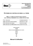
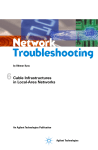
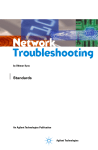
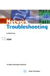
Network Troubleshooting by Othmar Kyas 9 FDDI An Agilent Technologies Publication Agilent Technologies 9 FDDI “Any time you think things seem to be going better, you have overlooked something.” ANONYMOUS 9.1 FDDI: Specification and Implementation Like Token Ring, the Fiber Distributed Data Interface (FDDI) is based on a token-passing principle. With this technique, access to the LAN medium is controlled primarily by means of a specific sequence of bits called a token. Unlike Token Ring, however, FDDI uses a dual ring architecture for increased S ta tio n 1 M A C R in g W r a p p in g S ta tio n 4 M A C A R in g W r a p p in g A B B A S ta tio n 2 A M A C B B fa ile d S ta tio n S ta tio n 3 Figure 9.1 Fault tolerance in FDDI: Ring recovery through wrapping SECTION II TROUBLESHOOTING LOCAL-AREA NETWORKS 264 FDDI 9 reliability, and its greater bandwidth allows a data speed of 100 Mbit/s. The dual ring architecture enables FDDI to tolerate the complete failure of one of its nodes with no significant effect on network performance. This fault-tolerant feature is called “ring wrapping”: if a station fails, the ring doubles back on itself on either side of the failed station, thus forming a single ring, isolating the source of error and providing continuous data transmission (see Figure 9.1). Two types of nodes are defined in FDDI: dual-attachment stations (DAS) and single-attachment stations (SAS). An SAS is attached to the primary ring through a concentrator, similar to the concentrators used in Token Ring. An SAS requires only a single FDDI port and can be inserted into or removed from the ring without affecting network operation. Dual-attachment stations require two ports attached to both the primary and secondary rings. Connecting or disconnecting a DAS disrupts ring operation. F D D I D A S F D D I c o n n e c tio n o p tio n s : D u a l- a tta c h e d s ta tio n s ( D A S ) a n d s in g le - a tta c h e d s ta tio n s ( S A S ) C o n c e n tra to r S A S P r im a r y S e c o n d a ry C o n n e c to r a s s ig n m e n ts o n th e D A S in te r fa c e S A S S A S P r im a r y P o rt A P o rt B S e c o n d a ry F D D I D A S Figure 9.2 Station connections in FDDI Dual homing is another fault-tolerant feature of FDDI for connection of critical devices, such as servers and routers. With dual homing, the component is attached to two concentrators. The second concentrator link remains passive unless the primary link fails. FDDI protocols can be implemented over two pairs of single-mode or multimode optical fibers, or over four pairs of shielded or unshielded twisted-pair copper SECTION II TROUBLESHOOTING LOCAL-AREA NETWORKS 265 FDDI 9 wires (STP, UTP). FDDI over copper wire is called Copper Distributed Data Interface (CDDI). 9.1.1 The Physical Layer in FDDI Networks The FDDI physical layer is defined for single- and multimode optical fiber, as well as for shielded and unshielded twisted-pair copper wire (CDDI). Transmission is limited to defined symbols in 4B/5B encoding. When an optical data medium is used, 4B/5B-encoded data streams are transmitted directly in the form of light pulses. With twisted-pair wiring, the Multi-Level Transition–ThreeLevel Technique (MLT-3) is used. MLT-3 alternates between three voltage levels, reducing the frequency of the transmitted signal to 31.25 MHz. FDDI and CDDI also have different idle signals: in FDDI, a bit stream consisting of binary 1s indicates an idle line station, whereas in CDDI the idle signal is a random series of 1s and 0s because a continuous sequence of 1s would distort the frequency spectrum and increase electromagnetic interference. The FDDI protocol uses three types of symbols: • Line-state symbols, indicating one of the following: • Quiet Line State (QLS) • Master Line State (MLS) • Halt Line State (HLS) • Idle Line State (ILS) • Active Line State (ALS) • Noise Line State (NLS); • Control symbols, including the starting delimiter, ending delimiter, and control indicators • Data symbols Line-state symbols are sent as padding bits during pauses in transmission and indicate the operating state of the FDDI ring. Halt symbols, for example, either announce control sequences or report the removal of invalid symbols, while at the same time minimizing any DC imbalance in signals on a CDDI ring. Quiet symbols report an absence of voltage transition, which means there is no signal in the line. Idle symbols indicate a normal operating state between transmissions. These consist of continuous padding bits, which provide clock information for synchronization. The starting delimiter (SD) and ending delimiter (ED) control symbols mark the beginning and end of a transmitted data sequence. The ending delimiter, however, is not necessarily the last symbol in a transmission; it may be followed by a set (S) or reset (R) control indicator. If no control indicators are sent, then the SECTION II TROUBLESHOOTING LOCAL-AREA NETWORKS 266 FDDI F D D I S y m b o l C o d in g D e c im a l B in a r y L in e s ta te s y m b 0 0 0 3 1 1 0 4 0 o ls 0 0 0 0 1 1 1 1 0 1 0 0 S y m b o l Q I H S ta r tin g d e lim ite r 2 4 1 1 0 0 0 1 7 1 0 0 0 1 J K D e s c r ip tio n Q u ie t Id le H a lt F ir s t s y m b o l o f th e S C p a ir S e c o n d s y m b o l o f th e S D p a ir D a ta s y m b o ls 3 0 0 9 2 0 2 1 1 0 1 1 1 4 1 5 1 8 1 9 2 2 2 3 2 6 2 7 2 8 2 9 1 1 1 0 1 0 1 0 1 1 0 1 0 1 0 0 1 0 0 1 1 0 1 1 1 0 0 1 0 0 1 0 1 1 0 1 1 1 0 1 1 0 1 1 1 1 1 1 1 0 0 0 1 0 0 0 1 1 0 1 1 1 0 1 1 1 0 1 1 1 0 1 1 1 0 1 1 0 0 0 1 3 In v a lid c o d e s 0 1 0 0 0 0 1 0 2 0 0 0 1 0 0 3 0 0 0 1 1 0 5 0 0 1 0 1 0 6 0 0 1 1 0 0 8 0 1 0 0 0 1 2 0 1 1 0 0 1 6 1 0 0 0 0 1 2 3 4 5 4 5 6 7 8 9 A B C D E E n d in g d e lim ite r 1 3 0 1 1 0 1 C o n tro l m a rk e rs 0 7 0 0 1 1 1 1 2 5 1 1 0 0 1 1 2 F T R S V o r H V o r H V V V V o r H V V o r H H e x a d e c im a l 0 1 2 3 4 5 6 7 8 9 A B C D E F B in 0 0 0 0 0 0 0 0 1 0 0 1 0 1 0 0 1 0 0 1 1 0 1 1 1 0 0 1 0 0 1 0 1 1 0 1 1 1 0 1 1 0 1 1 1 1 1 1 a ry 0 1 0 1 0 1 0 1 0 1 0 1 0 1 0 1 M a rk s th e e n d o f th e d a ta s tre a m L o g ic a l 0 ( r e s e t) L o g ic a l 1 ( s e t) T h e s e s y m b o ls v io la te th e c o fo r z e r o b its in th e c o d e s tr e a th e m a n d a to ry s e q u e n c e , a n n o t b e tr a n s m itte d . If r e c e iv e d , c o d e s 1 , 2 , 8 a n d s h o u ld a lw a y s b e in te r p r e te d T r a n s m is s io n o r d e r o f c o d e s y m b o l b its Figure 9.3 4B/5B symbol encoding in FDDI n d itio n s m o r d s h o u ld 1 6 a s H a lt. 9 SECTION II TROUBLESHOOTING LOCAL-AREA NETWORKS 267 FDDI 9 transmission ends with two ending delimiters. If there is an even number of control indicators, an additional ED follows the last control indicator. Valid data symbols are the 16 hexadecimal values from 0 to F, transmitted in any order. Invalid symbols are any symbols that do not fulfill this definition. A node may receive invalid symbols due to an error situation or during synchronization with the ring clock rate (see Figure 9.3). 9.1.1.1 FDDI Line States The line state is the fundamental indication of the operational status of the FDDI ring. It is monitored continuously by each node’s station management (SMT) entity. The various line states are signaled as described here: Quiet Line State (QLS) When a physical connection is first set up, a steady stream of quiet (Q) symbols is transmitted. QLS is also entered any time the signal is lost, or after 16 or 17 consecutive Q symbols are received. QLS ends when any symbol other than a Q is received. Master Line State (MLS) MLS is indicated by a continuous stream of alternating halt (H) and quiet (Q) symbols, and is also used to set up a new physical connection. This state is entered whenever eight or nine consecutive HQ or QH symbol pairs are received, and ends as soon as any other symbol pair is received. Halt Line State (HLS) HLS is entered when H symbols are transmitted continuously while a connection is being set up. This state is detected as soon as 16 or 17 H symbols are received, and exited when any other symbol is received or when the signal is lost. Idle Line State (ILS) The ILS, characterized by a continuous stream of I symbols, is entered while a connection is being set up and during the transmission pauses between data packets. The state is recognized when four or five consecutive I symbols are received. The elasticity buffer (see the following) may increase this value by up to 11 bits. ILS is exited when any other symbol is received or when the signal is lost. Active Line State (ALS) ALS indicates that the incoming bit stream consists of valid FDDI frames, meaning that the nearest upstream neighbor has an active connection to the SECTION II TROUBLESHOOTING LOCAL-AREA NETWORKS 268 FDDI 9 ring. This state is entered once a starting delimiter is received. ALS is exited upon receipt of any symbol other than I, n, R, S or T (n=any data symbol), upon loss of a valid signal, or on entering ILS. Noise Line State (NLS) This line state indicates that the incoming signals are distorted by noise and that the physical connection is faulty. This state is entered upon receipt of 16 or 17 consecutive invalid symbols. The following events are interpreted as noise: • • • • • Invalid signals Elasticity buffer errors while receiving A mixed symbol pair (such as a control indicator paired with a data symbol) An n, R, S or T symbol (or a symbol pair containing at least one of these symbols) received while the line state is not ILS or ALS Reception of an I, n, R, S or T symbol while the clock detect function (a mechanism that monitors clock synchronization) reports a synchronization error 9.1.1.2 The Elasticity Buffer Differences are bound to occur between a receiving node’s internal oscillator and the clock rate of the incoming bit stream due to the transmission medium and to tolerance limits in network components. If the transmission rate of a given station is significantly lower than the incoming data rate, data could be lost. To prevent this, each station has an elasticity buffer to compensate for differences of up to 4.5 bits, or 0.01 percent. The frequency of the local oscillator must meet the following specifications: Nominal frequency: 125 MHz ± 0.005% (50 ppm) Phase jitter at 20 kHz: < 8 degrees Harmonic content at 125.02 MHz: < 20 dB Nominal code bit time: 8.0 ns Nominal symbol time: 40.0 ns 9.1.1.3 Smoothing The smoothing function ensures that the preamble of an FDDI frame is not lost in the process of passing through a number of elasticity buffers. This function removes surplus symbols from oversized preambles and adds them to undersized preambles. The smoothing function can increase the length of a 0 to 13 symbol preamble to 14 symbols, and reduce a preamble of 15 symbols or more to a length of 14 symbols. Frames with preambles shorter than 12 symbols are SECTION II TROUBLESHOOTING LOCAL-AREA NETWORKS 269 FDDI 9 usually not forwarded on the FDDI layer, and frames with a preamble of less than 2 symbols are ignored altogether. 9.1.1.4 Repeat Filter If a station in the ring is acting as a repeater but the FDDI protocol stack does not check incoming signals, the repeat filter prevents the propagation of code violations and invalid line states. 9.1.1.5 Ring Delay To ensure trouble-free operation of the ring, every station with an FDDI MAC layer must have a minimum delay of 3 bytes, while stations without an FDDI MAC layer must guarantee a delay of 2 bytes. The resulting maximum ring delay is the sum of the delay caused by all stations and the signal delay inherent in the medium. Both the MAC layer and the SMT have timers that take this figure for maximum ring delay into account. The following parameters are used in calculating the overall delay: SD_Min: The minimum latency of a starting delimiter sequence in a station (default: 74 bits, or 592 ns). SD_Max: The maximum latency of a starting delimiter sequence in a station. The maximum extension due to the smoothing function is 2 symbols, or 10 bits; the elasticity buffer may add a similar delay: ± 4.5 bits = maximum addition of 9 bits Sampling and timing errors are estimated at a maximum of 4 bits. Consequently, SD_Max ≤ 592 ns + 4 + 80 + 80 = 756 ns P_Max: The number of physical FDDI interfaces in the ring. The default value is 1,000, which corresponds to 500 dual-attachment stations. D_Max: The maximum transmission delay of a starting delimiter sequence when no noise is present. Thus a combination of 1,000 FDDI interfaces, a ring length of 100 km and a signal propagation speed of 5,085 ns/km yields: D_Max £ (P_Max x SD_Max) + (2 x 100 x 5085) = 1.773 ms. The default value for D_Max should be less than 1.773 ms; the specification calls for 1.617 ms. 9.1.2 The FDDI Data Format There are two types of frames in FDDI networks: tokens and data packets. A token is 3 bytes long and consists of a starting delimiter, a frame control field, and an ending delimiter. A token is a special frame that is passed from station to SECTION II TROUBLESHOOTING LOCAL-AREA NETWORKS 270 FDDI 9 station and controls access to the LAN medium. If a given station receives a valid token, but cannot forward it for some reason (such as a ring timing error), then the station issues a new token. P A S D F C P A ........ P r e a m b le ( 1 6 o r m o r e s y m b o ls ) S D ...... .. S ta r t in g D e lim ite r ( 2 s y m b o ls ) E D F C ........ F r a m e C o n tr o l ( 2 s y m b o ls ) E D ...... .. E n d in g D e lim it e r ( 2 s y m b o ls ) Figure 9.4 Structure of an FDDI token All other data packets can have lengths of 12 to 4,500 bytes and consist of the following fields: preamble, starting delimiter, frame control, destination address, source address, information, frame check sequence, end of frame sequence, ending delimiter, and frame status. P A S D F C D A S F S S F S ............. P A ............... S D ............... F C ............... D A ............... S A ............... S ta rt o f F r P r e a m b le S ta r tin g D F ra m e C o D e s t in a tio S o u rc e A d S A IN F O F C S E D C o v e re d b y F C S a m e S e q (1 6 o r m e lim ite r ( n tro l (2 s n A d d re s d re s s (4 u e o re 2 s y m s ( o r n c e s y m y m b b o ls 4 o r 1 2 s b o ls ) o ls ) ) 1 2 s y m b o ls ) y m b o ls ) IN F O ........... F C S ............ E F S ............. E D ............... F S ............... In fo rm a F ra m e E n d o f E n d in g F ra m e F S E F S tio C h F ra D e S ta n (0 e c k m e lim tu s o r S e S e ite r (3 m q u q u (1 o r o re s y e n c e e n c e s y m b m o re m b o l p a ir s ) ( 8 s y m b o ls ) o l) s y m b o ls ) Figure 9.5 Format of an FDDI frame 9.1.2.1 Token and Data Packet Fields Preamble (PA) A preamble consists of at least 16 idle symbols, although the length can vary during circulation through the ring due to differences in nominal frequency and to smoothing and elasticity buffering. Frames with a preamble of fewer than 12 symbols are not copied into the destination station’s receive buffer. Starting Delimiter (SD) Every frame, including tokens, begins with this field, which consists of the symbol sequence JK. SECTION II TROUBLESHOOTING LOCAL-AREA NETWORKS 271 FDDI 9 Frame Control (FC) C C .......... C la s s b it L F F L ........... A d d r e s s le n g th b it Z Z Z Z F F ........ F o r m a t b its Z Z Z Z .... C o n tr o l b its Figure 9.6 The frame control field in FDDI The frame control field identifies the frame type. It consists of frame class bits, address length bits, format bits, and control bits. Frame Class bit C=0: Frame Class bit C=1: Address Length bit L=0: Address Length bit L=1: The frame is asynchronous The frame is synchronous 16-bit MAC addresses 48-bit MAC addresses The frame format bits (FF), together with the C, L and ZZZZ bits, indicate the frame type as follows: CLFF bits ZZZZ bits 0X00 1000 1100 0L00 1L00 1L00 1L00 CL01 0L01 1L01 0L00 0L00 CL10 CL11 X r L C 0000 0000 0000 0001 – 1111 0001 – 1111 0010 0011 r000 – r111 RPPP Rrrr 0001 – 1111 1111 r000 – r111 Rrrr Any value Reserved and set to 0 Length Class Void Frame (content is ignored) Unlimited token Limited token Station Management frame MAC frame MAC beacon frame MAC claim token frame LLC frame Asynchronous transmission with priority (LLC) Synchronous transmission (LLC) SMT frame Next Station Addressing SMT frame Reserved for implementation For future standardization SECTION II TROUBLESHOOTING LOCAL-AREA NETWORKS 272 FDDI 9 The control bits, in conjunction with the corresponding CLFF bits, have the following meanings: MAC Beacon Frames (1L00 0010) MAC beacon frames are transmitted when the ring is unable to recover from an error situation, usually a hardware fault that results in signal failure, jabber frames, or frequency differences. MAC Claim Token Frames (1L00 0011) These frames are usually transmitted when a token is lost. When a station receives a claim token frame containing its own address as the source, it reinitializes the ring and issues a new token. SMT Next Station Addressing Frame (0L00 1111) This frame is used for station management functions. LLC Frame (0L01 rPPP) This LLC frame is used for asynchronous transmission. The last three bits, PPP, indicate the priority. The highest priority is 111 and 000 is the lowest. LLC Frame (1L01 rrrr) This LLC frame is used for synchronous transmission. Address Fields The address fields in FDDI can be either 16 or 48 bits in length. Stations with 16-bit addresses, however, must be able to function in rings with 48-bit addresses. This means they must be able to repeat 48-bit addresses and to react correctly on receiving claim token and broadcast frames with 48-bit addresses. Stations with 48-bit addresses must have also a fully functional 16-bit address and be able to recognize other 16-bit addresses. 4 8 - b it a d d r e s s I / G U / L 1 6 - b it a d d r e s s .......................... I / G .......................... 4 6 b its U n iv e r s a l/lo c a l b it In d iv id u a l/g r o u p b it Figure 9.7 The address field in FDDI 1 5 b its SECTION II 273 TROUBLESHOOTING LOCAL-AREA NETWORKS FDDI 9 The first bit of a destination address indicates whether the destination is an individual address (bit 1 = 0) or a group address (Bit 1 = 1). (bit 1 of the source address is always set to 0, however.) A group address consisting entirely of 1s is a broadcast address used to send a frame to every station in the ring. An address consisting entirely of 0s is called a “zero address”: frames with this address are not intended for any station. The second bit in a destination address shows whether the address is locally administered (bit 2 = 1) or universally administered (bit 2 = 0). Figure 9.8 shows a FDDI data packet that has been decoded using a protocol analyzer. Occasionally FDDI addresses are shown in both the MSB (Most Significant Bit First) format and the canonical format used in Ethernet and other network protocols. To convert between the canonical bit order and MSB format, the nibbles (half-bytes) are switched and the bit order in each half reversed. Thus a hexadecimal 43 becomes 34 or, in binary, 0011 0100. Reversing the bit order of each nibble yields 1100 0010 or, in hexadecimal, C2. The canonical address 01-80-C2-00-01-10 corresponds to an MSB address of 80-01-43-00-80-08. Figure 9.8 Decoding an FDDI frame using the Agilent Advisor protocol analyzer SECTION II TROUBLESHOOTING LOCAL-AREA NETWORKS 274 FDDI 9 Information Field The information or data field contains user data—the payload of the FDDI frame. The data type is described in the frame control field and evaluated accordingly by the receiving node’s MAC, LLC or SMT module. The length of the data field is variable, but the length of the entire frame must not exceed 9,000 symbols or 4,500 bytes. Frame Check Sequence (FCS) This is a 32-bit checksum calculated from the content of the frame control, source address, destination address, and data fields. Each receiving station evaluates the checksum. Ending Delimiter (ED) The ending delimiter marks the end of a token or data packet. This field consists of two consecutive T symbols in a token or one T in a data packet. Frame Status (FS) The frame status field consists of control indicators that follow the ending delimiter. The first three control indicators—E (error detected), A (address recognized) and C (frame copied)—are required, and are set to R (reset) by the source station on transmission. Other control indicators are optional. E A C R /S R /S R /S T .......... T e r m in a te s y m b o l R /S R /S . . . T R /S ....... S ta tu s b it s e t ( 1 ) o r r e s e t ( 0 ) Figure 9.9 The frame status field in FDDI Error Detected (E) If a ring node detects an error in the frame, it sets the value in the E field to S. Address Recognized (A) When a node recognizes the destination address of a frame as its own, it sets the value in the A field to S. Frame Copied (C) When the receiving node copies the frame into its receive buffer, it sets the value in the C field to S. SECTION II TROUBLESHOOTING LOCAL-AREA NETWORKS 275 9.1.2.2 FDDI 9 Timers and Counters Every FDDI node has three timers for controlling ring activities. The values set for these timers are calculated using the following parameters: D_Max = maximum ring delay (default: 1.617 ms) M_Max = 1,000 (maximum number of FDDI interfaces in the ring) I_Max = 25.0 ms (maximum station insertion time) A_Max = 1.0 ms (maximum signal access time) Token_Time = 0.00088 ms (the time it takes to transmit a token (6 symbols) with preamble (16 symbols)) L_Max = 0.0035 ms (maximum time between receipt of token and start of transmission) F_Max = 0.361 ms (maximum time for transmitting a data packet; equals the transmission time for 9,000 symbols plus 16 preamble symbols) Claim_FR = 0.00256 ms (time required for transmission of a claim token frame) S_Min = 0.3545 ms (the time it takes for the ring to recover from the effects of noise: S_Min (F_Max + L_Max) Token Holding Timer (THT) The THT controls the amount of time during which a station may transmit data packets. Once the station has obtained a token, it may transmit until this timer expires and the Token Rotation Timer (TRT) remains below the node’s priority level, T_Pri. When a node receives a token, it resets its THT with the value remaining in the TRT; (see the following). Timer Valid Transmission (TVX) The TVX allows a node to recover from an error situation: TVX > max (D_Max, F_Max) + Token_Time + F_Max + S_Min, and TVX > 2.35 ms The default value of TVX is at least 62,500 symbol times or 2.50 ms. Token Rotation Timer (TRT) The TRT controls the ring timing during normal operation. When this timer runs out, or when an early token is received (a token that arrives at a node before the TRT runs out), the TRT is initialized with the value currently valid for the SECTION II TROUBLESHOOTING LOCAL-AREA NETWORKS 276 FDDI 9 operative Token Rotation Timer, the T_Opr. In the former case, the Late counter, Late_Ct, is also increased by one. T_Opr is between the T_Min and T_Max values for the ring, and is set upon completion of a claim token process (see the following). Due to the nature of the token-passing protocol, it may take up to a whole T_Opr period for a station to receive a token. If a station offers a guaranteed T_Resp, then T_Opr should be set to 0.5 T_Resp. If a station’s T_Min value is higher than T_Opr, the station cannot participate in normal ring traffic. T_Min = 4.0 ms (default) T_Max = 4 · T_Init > 165 ms, where T_Init is the time the ring has operated without noise: T_Init = T_React + T_Resp < 40.58 ms, where T_React < I_Max + D_Max + A_Max + TVX, and T_React < 30.24 ms T_Resp < ((3 · D_Max) + (2 · M_Max · Claim_FR) + S_Min), and T_Resp < 10.34 ms Late_Ct is set to 1 when the node is initialized or reset, and is incremented every time the TRT runs out without a token having been received. Once a token is received, the Late_Ct is reset to 0. To simplify troubleshooting and the isolation of failure domains in the ring, every FDDI station has counters that count every data packet, whether defective or not. However, the frames are counted only if they end in an ending delimiter (T symbol). Data packets that end with idle or invalid symbols are not counted. Frame_Ct Counts all frames received. Error_Ct The number of frames identified by this node as defective: in other words, those frames whose error detected (E) field is R on arrival at this node, but S on retransmission. Frames received with E already set to S are not counted. Lost_Ct The number of frames, including tokens, that are in the process of being received by a station when an error occurs. The lost counter is incremented and the rest of the frame is replaced with idle symbols. The next node does not count this frame because it ends with idle symbols. SECTION II TROUBLESHOOTING LOCAL-AREA NETWORKS 277 9.1.3 FDDI 9 Process Control in FDDI Networks Access to the medium in FDDI networks is controlled by a token; timers and counters control various related processes. A station with data to send must wait for a free token. When the token is received, transmission can begin. Unlike Token Ring, in which a transmitting node waits for its frame to return before releasing the token, FDDI nodes release the token as soon as transmission is completed. Each node is responsible for removing the frames that it transmitted from the ring. When a node detects a frame containing its own address as the source, it replaces the data field of the frame with idle symbols. This results in frame fragments consisting of the PA, SD, FC, DA and SA fields followed by idle symbols. These “remnants” do not negatively affect ring performance, however, because they have recognizable defects, such as the lack of an ending delimiter, they are deleted by the next station that detects them while in the transmitting state. Stations that are not in the transmitting state simply repeat and amplify the incoming bit stream. A FDDI ring supports two types of communication: synchronous, in which each node is granted a defined portion of the available bandwidth, and asynchronous with dynamic bandwidth sharing. If a token is received by a node before the node’s TRT has reached the TTRT (this is known as an early token), the token can be used for synchronous or asynchronous transmission. If the token is late, however, Late_Ct is increased by one, the TRT is initialized with the value for T_Opr, and the node may only transmit synchronously. The Late_Ct is reset to 0 and asynchronous transmission is allowed only after a token has been received within the TTRT. This ensures an average synchronous response time ≤ TTRT and a maximum synchronous response time of 2 TTRT. 9.1.3.1 Synchronous Transmission In synchronous transmission, every station is assigned a certain bandwidth, expressed as a percentage of the TTRT. This bandwidth allocation is 0 when a node is initialized; a higher value is then negotiated by the SMT. The sum of all allocated bandwidths must not exceed the maximum usable synchronous bandwidth, Bsyn_Max: Bsyn_Max = TTRT – (D_Max + F_Max + Token_Time) 9.1.3.2 Asynchronous Transmission There are two types of tokens for asynchronous transmission: nonrestricted tokens, which are available to all ring nodes, and restricted tokens, which are reserved for certain nodes. When the ring is (re)initialized, a nonrestricted token is issued. At this point, priority levels can be distinguished by assigning SECTION II TROUBLESHOOTING LOCAL-AREA NETWORKS 278 FDDI 9 T_Pri values. A node can capture a nonrestricted token only if the node’s T_Pri is higher than the TRT. Thus heavy ring traffic can be relieved to a certain extent by defining low T_Pri values. As soon as a node captures a token, its THT is initialized with the value remaining in the TRT. The TRT itself is initialized with the current value of TTRT, so that the time of the next token rotation is measured relative to the target time. If a node has a large amount of data to transmit in a short time, it initiates the restricted token state. With this technique, the node first captures a nonrestricted token and begins its data transmission. When the THT runs out, the node issues a restricted token, which is simply forwarded by all other nodes until it is returned to its source node. The restricted token state lasts until completion of the transmission for which it was started, usually a period of several TRTs. While the ring is in this state, all other asynchronous transmission is stopped. Synchronous transmission, however, which uses both types of token, is not affected. The maximum duration of the restricted token state is negotiated by the SMT. Claim Token Process All nodes monitor the ring for errors that necessitate reinitialization of the ring, such as inactivity (when the TVX runs out) or signal errors (if TRT runs out and Late_Ct is already set, for example). When a node detects such an error, it sets the ring operational variable to 0 and transmits a claim token frame indicating its desired TTRT. It begins checking the TTRT values of all claim token frames it receives. The lower the TTRT value, the higher the sender’s priority. If the TTRTs of two frames are equal, the one with the higher source value has higher priority. When a node detects claim token frames with a higher priority level than its own, it stops issuing claim token frames. Eventually, the ring contains only claim token frames from the node with the lowest TTRT. This node initializes the ring, resets T_Opr to its own TTRT, starts the TRT and issues a nonrestricted token. If a station’s TRT expires before another higher-priority node initializes the ring, then this station begins sending claim token frames again rather than sending beacon frames. This prevents sporadic beacon frames in the ring. The token cannot be captured by any station during its first rotation because the ring operational variable is cleared when the claim token process starts. Once the first rotation has been completed, both Ring_Operational and Late_Ct are set to 1 and TRT is initialized. Synchronous transmission can begin in the second token rotation; asynchronous transmission in the third. Beacon Process If a node’s TRT runs out while a node is in the claim token state, the node considers the claim token process to have failed and starts the beacon process. SECTION II TROUBLESHOOTING LOCAL-AREA NETWORKS 279 FDDI 9 As a rule this only happens when the ring is physically interrupted and must be globally reconfigured—when one logical ring is broken into two, for example. After entering the beacon state, the node resets its TRT and transmits beacon frames continuously. A node that is not in the beacon state repeats any beacon frames it receives. When a node receives its own beacon frames, it assumes that the ring has recovered and begins the claim token process again. 9.1.3.3 The FDDI Station Management Specification (SMT) SMT in FDDI is a special functional module integrated in the FDDI protocol stack that provides increased security and automatic fault recovery mechanisms. SMT includes the following functions: • • • • • • Inserting the node in the ring and removing it Reconfiguring the paths in the node (when a link fails, for example) Checking the physical connection before inserting the node Controlling node behavior during the beacon process Reporting the current node configuration Transmitting status report frames to isolate possible error sources SMT is composed of four modules: Entity Coordination Management (ECM), Physical Connection Management (PCM), Configuration Element Management (CEM) and Ring Management (RMT). Entity Coordination Management (ECM) ECM controls the optical bypass system as well as all other SMT functions. As soon as an FDDI node becomes active, ECM deactivates the optical bypass and starts all other SMT functions. Similarly, when the node leaves the ring, ECM first stops all other SMT functions and then reactivates the optical bypass. In the context of these processes, ECM also performs a number of tests on the physical layer: • • • • Checks all internal data paths in the node Performs loopback tests Checks the parameters passed to the FDDI layer (TTRT, etc.) Tests the FDDI recovery processes (beacon, claim token, etc.) Physical Connection Management (PCM) PCM controls station output and the redundant fiber-optic line to the neighboring node. Together with the PCM of the neighboring node, it tests the connection between the two nodes and checks the BER to determine whether a connection can be set up or not. Each of the station’s ports has its own PCM. The 10 bits used in this bit signaling between nodes are explained in the following: SECTION II TROUBLESHOOTING LOCAL-AREA NETWORKS 280 Bit 0 FDDI 9 Always set to 0 (reserved for future applications) Bits 1, 2 Indicates the station’s own interface type: 00 = A, 01 = B, 10 = S, 11 = M Bit 3 Compatibility of the output ports: If Bit 3 = 0 for both ports, the connection is not set up. Bits 4, 5 Link Confidence Test (LCT) : This function tests the reliability of the connection. How long the test takes depends on the previous BER: 00 = short (50 ms) 01 = medium (500 ms) 10 = long (5 s) 11 = extended (50 s) Bit 6 Indicates whether the MAC layer is used during the LCT Bit 7 Indicates whether the BER was low enough to pass the LCT Bit 8 Indicates whether a MAC loopback test should be performed Bit 9 Indicates whether there is a MAC layer at the station output port Once the PCM has reached the active state, the station begins transmitting either QLS signals or data. The PCM also starts the link error monitor (LEM), which checks the BER in the FDDI port and deactivates the port if the BER is too high. When the BER reaches 10–8, a warning is sent; if it goes up to 10–7, the connection is shut down. Configuration Element Management (CEM) CEM configures the station’s internal data paths, including the primary, secondary and local paths. For this purpose, each port has a logical module called the configuration control element (CCE), which distributes incoming data among these internal paths. When the CEM changes the status of a CCE, it also deletes all data in the ring by transmitting ILS signals. This causes the ring nodes to begin transmitting claim token frames. Ring Management (RMT) RMT controls the FDDI protocol stack. It is not active until a physical connection exists and the input and output ports have been assigned to internal data paths. The RMT has six main tasks: • It initializes the MAC layer once a physical connection has been set up. • When the MAC layer is not active, it checks for duplicate addresses by monitoring claim token and beacon processes. To do this, the station’s RMT SECTION II TROUBLESHOOTING LOCAL-AREA NETWORKS 281 • • • • FDDI 9 evaluates all claim token and beacon frames: if a node receives its own claim token or beacon frame after more than 2 D_Max, another station has the same address (D_Max is the maximum length of time a frame can take to travel around the entire ring). Furthermore, the station assumes the existence of a duplicate address if it receives a claim token frame with its own address as the source but a TTRT that differs from its own. When the MAC layer is active, the RMT checks for duplicate addresses by verifying the A bit in neighbor information frames. If it detects a duplicate address, the RMT reacts in one of three ways: it closes down the connection, removes the station from the ring, or changes the FDDI MAC address. The RMT also detects and responds to beacon states. It controls and initiates Halt Line States. It supports and monitors restricted tokens. When a station receives a restricted token, the RMT starts a timer to monitor the duration of the restricted-access dialog. If the timer expires, a claim token or beacon process is triggered. SMT Agents In addition to the four functional modules described previously, every SMT also has an SMT agent that checks all incoming FDDI frames and acts on them if necessary. The SMT agents use a number of special FDDI ring management frames in performing their tasks: Neighbor Information Frame (NIF) NIFs are used to determine the identities of neighboring nodes. Each node broadcasts a NIF approximately every 30 seconds. The first station to receive an NIF—with the A bit (address recognized) cleared—is the nearest downstream neighbor of the node that sent that frame; this neighbor transmits an answer. Status Information Frame (SIF) SIFs provide information about the status of a node. There are two types of SIF: • SIF configuration frames describe the station’s current configuration, in• cluding the number of input and output ports, the number of interfaces, and information on neighboring nodes. SIF operation frames describe the current operating state of a node, including MAC parameters, LEM status of the ports, and frame counters. SIFs can be transmitted as request or response frames. An SIF configuration response frame can contain up to 10 parameters, including time stamp, station descriptor, SMT versions supported, station state, station policy, added transmission delay, neighboring nodes, path descriptors and parameter change count. SECTION II TROUBLESHOOTING LOCAL-AREA NETWORKS 282 FDDI 9 SIF operations response frames can contain the following: time stamp, MAC status, port LEM status, MAC frame counter, MAC frame not-copied counter, MAC priority values, elasticity buffer status, vendor code, user field and parameter change count. Echo Frame (ECF) When an ECF is received, the SMT copies the data field and returns it as an echo response frame. Request Denied Frame (RDF) When the SMT receives a data packet with an unknown format or with an SMT version it does not support, it transmits an RDF. Other causes for denial of a request may be oversized frames or the lack of reception authorization. Status Report Frame (SRF) These frames report changes in the station’s status, including any of the following events: • • • • • • • • • • • • Change in configuration Unwanted connection attempts MAC: neighbor change MAC: Frame error condition MAC: Path change condition Port: Path change event Port: Link-error-rate condition Port: Wrapping in a neighboring station MAC: Frame not copied MAC: Duplicate address Port: Elasticity buffer error Vendor-specific events The hold-off and back-off timers ensure that the station is not flooded with SRFs. The hold-off timer prevents transmission of status change reports more than once every 2 seconds, while the back-off timer controls the interval between change report transmissions. Because no acknowledgement is sent in response to these frames, the SMT repeats SRFs at ever-increasing intervals (2, 4, 8, 16, 32 seconds). SECTION II TROUBLESHOOTING LOCAL-AREA NETWORKS 283 FDDI 9 Parameter Management Frame (PMF) Network management devices can use these frames to read or change certain SMT variables. The parameter management process corresponds to the structure of network management protocols, such as SNMP or CMIP. There are two types of PMF: • PMF Get • PMF Set Extended Service Frame (ESF) The ESF format can be used to define custom SMT frames. Resource Allocation Frame (RAF) RAFs are used to allocate synchronous bandwidth. 9.1.4 Design Guidelines for FDDI Networks The guidelines for designing FDDI networks include specifications for the various cable types as well as limits on the maximum distances between neighboring nodes and the maximum number of nodes per ring. The maximum distance between two adjacent nodes is 2 km on multimode fiber rings, 40 km on single-mode fiber rings, and 500 meters in low-cost fiber (LCF) rings. It is important to keep in mind that when a ring wraps due to node failure, the ring length doubles. The wavelength used in all fiber optic rings is 1,300 nm. The specifications for diameter and signal power are as follows: Multimode: Diameter: 62.5/125 mm, 50/125 mm, 85/125 mm, 100/140 mm Signal power: -14 dBm to -20 dBm Single mode: Diameter: 9/125 mm Signal power: -14 dBm to -20 dBm (Category 1) -15 dBm to -37 dBm (Category 2) When shielded (STP-1) or unshielded (UTP-5) twisted-pair cabling is used, the maximum distance between two nodes is 100 meters. There are no values defined for minimum distances between nodes in either FDDI or CDDI. 9.1.4.1 Connection Rules for SAS and DAS Nodes When connecting a dual-attachment station (DAS), port A of one DAS must be connected to port B of the neighboring node. For single-attachment stations SECTION II TROUBLESHOOTING LOCAL-AREA NETWORKS 284 FDDI 9 (SAS), the S port of the node must be connected to the M port of the concentrator: A B M S A – + + – B + – + – M + + x + S – – + – + recommended connection – connection could lead to problems; may be deactivated in the manufacturer’s default configuration x connection not permitted 9.1.5 FDDI Standards ANSI X3.139-1987, ISO 9314-2:1989, Media Access Control (MAC) ANSI X3.148-1988, ISO 9314-1:1989, Physical Layer Protocol (PHY) ANSI X3.166-1990, ISO 9314-3:1990, Physical Layer, Medium Dependent (PMD) ANSI X3.229-1994, ISO 9314-6, Station Management (SMT) ANSI X3.184-1993, ISO 9314-4, Single-Mode Fiber PMD (SMF-PMD) ANSI X3.237-1995, ISO 9314-9, Low-Cost Fiber PMD (LCF-PMD) ANSI X3.263-1995, ISO 9314-10, Twisted Pair PMD (TP-PMD) ANSI X3.278, Physical Layer Repeater (PHY-REP) ANSI X3.262 ISO 9314-13, Conformance Test PICS Proforma for FDDI (CT-PICS) ANSI X3.245-199x, ISO 9314-26, Abstract Test Suite for MAC (MAC-ATS) ANSI X3.248-199x, ISO 9314-21, Abstract Test Suite for PHY (PHY-ATS) ANSI X3.255-199x, ISO 9314-20, Abstract Test Suite for PMD (PMD-ATS) ANSI X3T9.5/92-102, Rev 1.4, Abstract Test Suite for SMT (SMT-ATS) RFC 1285, FDDI-MIB SECTION II 285 9.2 9.2.1 TROUBLESHOOTING LOCAL-AREA NETWORKS FDDI 9 Troubleshooting FDDI Networks Gathering Information on Symptoms and Recent Changes The first step in any troubleshooting process is to gather information. The more information you have about the symptoms and characteristics of a problem— including when it first occurred—the better your chances of solving the problem quickly and efficiently. Typical questions you might ask at this stage include: • Do the symptoms occur regularly or intermittently? • Are the symptoms related to certain applications, or do they affect all • • • • • • • • network operations? Do the symptoms correlate to other activities in the network? When was the first occurrence of the symptom? Was there any change in any hardware or software network component? Has anyone connected or disconnected a PC (laptop or desktop) or any other component to or from the network? Has anyone installed an interface card in a computer? Has anyone stepped on a cable? Has any maintenance work been performed in the building recently (by a telephone company or building maintenance personnel, for example)? Has anyone (including cleaning personnel) moved any equipment or furniture? 9.2.2 Starting the Troubleshooting Procedure Troubleshooting in FDDI LANs is primarily performed using cable testers for optical fiber and twisted-pair copper wire, protocol analyzers, and special FDDI ring management software to track and display SMT functions. FDDI has several self-diagnosis functions that enable it to recover from a number of critical states on its own. Key requirements for successful troubleshooting in an FDDI network include a detailed understanding of its operational processes and of the SMT functions. If the ring is still functional, the first step in the troubleshooting procedure involves using a protocol analyzer to determine the main operating statistics of the network. These statistics include ring load as a percentage of capacity, throughput in frames per second, token rotation time, the numbers of stripped and void frames, the numbers of claim and beacon frames, the number of frames with undersized preambles, and the number of frames with invalid checksums. SECTION II TROUBLESHOOTING LOCAL-AREA NETWORKS 286 FDDI 9 The analysis of these statistics often points to possible causes of the problem. Furthermore, all SMT frames should be recorded and analyzed, including SRF and RDF, which can point to the failure domain. Furthermore, you can use the SHOW INTERFACES FDDI command (exact command depends on the equipment type) to check the statistics of the interface cards of ring nodes The following is a sample result of a SHOW INTERFACES FDDI command entered on a DAS: Fddi 0 is up, line protocol is up Hardware is cBus Fddi, address is 0000.0b14.32e2 (bia 0000.0b14.32e2) Internet address is 18.187.1.29, subnet mask is 255.255.254.0 MTU 4470 bytes, BW 100000 Kbit, DLY 100 usec, rely 255/255, load 1/255 Encapsulation SNAP, loopback not set, keepalive not set ARP type: SNAP, ARP Timeout 3:00:00 Phy-A state is active, neighbor is B, cmt signal bits 008/20C, status ILS Phy-B state is active, neighbor is A, cmt signal bits 20C/008, status ILS CFM is thru A, token rotation 5000 usec, ring operational 2:13:46 Upstream neighbor 0000.7640.0e50, downstream neighbor 0000.0a02.5bf2 Last input 0:00:00, output 0:00:00, output hang never Last clearing of “show interface” counters 1w3d Output queue 0/40, 0 drops; input queue 0/75, 132 drops Five minute input rate 264000 bits/sec, 81 frames/sec Five minute output rate 267000 bits/sec, 88 frames/sec 33457636 frames input, 2146812161 bytes, 8 no buffer Received 2456722 broadcasts, 0 runts, 0 giants 15256 input errors, 11561 CRC, 176 frame, 0 overrun, 53676 ignored, 0 abort 124789478 frames output, 4146709113 bytes, 379 underruns 0 output errors, 0 collisions, 0 interface resets, 0 restarts 5460 transitions, 0 traces, 2405 claims, 4 beacon If the problem cannot be isolated using the information described previously, additional trend measurements are necessary. This involves recording the main operating parameters over a period of hours, or even days, and analyzing the results for correlations. In this way, possible causes can be systematically eliminated until the source of the problem is limited to a small area. The steps to take after the basic measurements have been performed using a protocol analyzer depend on the nature of the symptoms. If the symptoms can SECTION II 287 TROUBLESHOOTING LOCAL-AREA NETWORKS FDDI 9 Figure 9.10 Trend measurements and correlation analysis in FDDI networks using the Agilent Advisor protocol analyzer be localized, occur periodically, or can at least be reproduced, then the troubleshooting process continues with the network component nearest to the problem. If the problem source cannot be detected there, the range of analysis is successively expanded. For example, if the problems are found to be related to a single network node, the next step is to analyze the station’s software and hardware components. If no fault is found, the examination progresses to the patch cables, the connectors, the wall jack, the concentrator, and the cabling. If the problem cannot be localized at all, or if problems that were thought to have been isolated cannot be pinpointed, then the only way to find the source of the problem is through systematic segmentation of the network. To do this, divide the ring physically into two rings, determine which of these still shows the error condition, divide that ring into two, and so on until the error is localized. This method causes considerable disruption in network operation and is therefore applied only as a last resort, when the problem itself severely impairs normal network operation. SECTION II TROUBLESHOOTING LOCAL-AREA NETWORKS 288 FDDI 9 If the symptoms occur intermittently, long-term measurements are necessary. These must be performed continuously until the basic network operating statistics have been measured during the occurrence of the fault. This information usually provides the first clue to the error source. Furthermore, it is essential to log the exact time of intermittent error events. Later this information can be used to find temporal correlations with other events in the network or on a given node, such as backups, the start of specific applications, connections through routers, access to the Internet, users’ working hours, or other possible factors. If this does not help to track down the error, you may have to resort to the segmentation method. Depending on which causes the least inconvenience to users, you can either systematically disable network functions and applications or physically separate concentrators. These methods usually lead to the error source. 9.2.3 Error Symptoms in FDDI The most common symptoms of problems in FDDI networks are ring wrapping, a large number of claim or beacon frames, frequent reinitialization of the ring (ring state transitions), and large numbers of lost token errors accompanied by increasing numbers of claim and beacon frames. A physical break in the cabling or a power outage in a station or concentrator usually triggers ring wrapping. You can usually identify the node at which the wrap occurred by analyzing status information frames with a protocol analyzer, or by querying the status of interfaces, such as bridge or router ports. Then you can test all the components (connector, cable, concentrator, interface cards, bridge/router ports) that were cut out of the ring when it wrapped. Large numbers of claim and beacon frames in the ring in conjunction with frequent transitions may indicate problems either in the cabling (kinks, contaminated connectors) or in the transmit and receive ports of an interface card. In such cases, trend measurements of the relevant parameters (concurrent tracking of active stations and error rate) and an analysis of status information frames can be useful in tracing the fault. 9.2.3.1 Principal Error Conditions During Normal Ring Operation; Claim Initiator Identification State transitions in an FDDI network do not necessarily constitute a sign of trouble in the ring. Ring reinitialization is usually triggered by a node’s LEM function when the error rate in its interface exceeds a certain threshold. In this case, the ring is temporarily deactivated while the LEM tests the link in question. The ring is also reinitialized any time a node’s TVX expires, indicating that SECTION II TROUBLESHOOTING LOCAL-AREA NETWORKS 289 FDDI 9 the node has not received a token or other valid data packet in the last 2.5 ms. The reinitialization procedure takes only a few milliseconds, so the higher-layer protocols, with timer values on the order of whole seconds, are not affected. If an error that triggers reinitialization occurs as part of normal operation—when a node is connected or disconnected, a router or bridge is rebooted, etc.—then the reinitialization process does not indicate a problem. If transitions happen several times a minute, however, then the higher-layer protocols are affected. If you can localize the station that started the claim process, you should be able to isolate the failure domain and solve the problem. To determine which station initiated a claim process, assign a different TTRT value to each station in the ring. To illustrate this method, consider a ring with three nodes. Node A has TTRT=10, Node B has TTRT = 15, and Node C has TTRT = 5. Analyze the claim counters (Claim_Ct) in each station. In this example, assume Node B starts the claim process. Node A repeats the frame transmitted by Node B, because TTRTA > TTRTB. Node C, however, replaces B’s frame with its own claim frame because TTRTC < TTRTB). The claim counters of the three stations contain the following values at this point: B=1, C=1, A=0. In this way the combination of TTRT and claim counter values can be used to trace the node that initiated the claim process. S ta tio n C T T R T 5 S ta tio n A T T R T 1 0 C la im C In itia to r C la im S ta tio n B T T R T 1 5 C o u n te r A C la im C o u n te r B C la im C o u n te r C A 1 0 1 B 0 1 1 0 0 1 Figure 9.11 Identifying the node that initiated a claim process in an FDDI network SECTION II TROUBLESHOOTING LOCAL-AREA NETWORKS 290 9.2.3.2 FDDI 9 Void Frames A void frame is one with the value 0X00 0000 in its frame control field, where X stands for the address length bit and has a value of either 1 (indicating a 48-bit address) or 0 (indicating a 16-bit address). Void frames are not actually data packets and are usually ignored by all ring nodes. Some manufacturers use void frames for special purposes, however, such as deleting frame fragments or stripped frames. Thus the occurrence of void frames does not necessarily indicate an error condition. Contact the manufacturer of the components in question for further details. 9.2.4 Cabling Problems As in other networks, cabling problems are frequent causes of errors in FDDI networks. Typical causes include defective or low-quality cables; cable lengths exceeding the specified maximum; defective or low-quality connectors or, in a CDDI network, incorrect impedance; or electromagnetic interference (noise) caused by air conditioning systems, photocopiers, pagers, elevators or production environments. These problems are discussed in detail in the chapter on cabling. Two factors that must be mentioned with specific reference to FDDI, however, are the maximum bit-error-rate (BER) permitted between two FDDI stations and the optical bypass function. The BER due to signal repetition must not exceed 2.5x10⁻¹⁰. (If the signal power exceeds the minimum requirement by 2 dB, then the BER must not exceed 1x10–12). At the receive port, a signal power of –31 dBm or more must be recognized as valid within 100 µs. Another possible source of errors is the optical bypass function in ring nodes. This function isolates a node upon failure so that the double-ring architecture of the network is maintained. Without the bypass function, failure of a node causes the ring to wrap, which means it doubles back on itself and is reconfigured as a single ring. The following specifications are defined for bypass functions used in FDDI: Min Max Units Attenuation (input – output) 0.0 2.5 dB Optical switching time — 15 ms Station switching time — 25 ms SECTION II TROUBLESHOOTING LOCAL-AREA NETWORKS 291 FDDI 9 The optical switching time is the time during which the primary and secondary optical signal is interrupted during the switching process (measured from the time the signal drops more than 1.5 dB below the original signal level S1 to the time the signal recovers above S1-1.5 dB). The station switching time is the duration of the insertion or removal process from beginning to end (completion is defined as 1.5 dB below the final signal level). Other problems in the physical layer that are not specific to FDDI, and their remedies, are discussed in detail in Chapter 5. 9.2.5 Problems with FDDI Interface Cards Typical symptoms of defective interface cards in FDDI rings are high numbers of claim and beacon frames in conjunction with frequent transitions. The first step in localizing a defective FDDI NIC is to identify suspicious nodes on the network. Begin by making a list of all network nodes that transmit defective frames. Most protocol analyzers provide this information with fully automatic test programs. You can also use the method described in Section 9.2.3 to determine which node initiates the claim process. If this does not pinpoint the problem, or if the symptoms are intermittent, try the correlation method: begin by simultaneously charting the activity of the suspicious nodes and the error rate in the network. If there is a correlation between the activity of a certain node and the error rate, then you have probably found the defective interface card. 9.2.6 Problems with Bridges Bridges are components that connect network segments on OSI Layer 2 (the MAC layer). Bridges buffer and filter the frames they receive from connected segments and transmit them to their destination segments without regard to higher-layer protocols. The basic functions of bridges are described in detail in the chapter on Ethernet networks; the following discussion deals only with bridge problems specific to FDDI. 9.2.6.1 Diagnosing Bridge Problems The challenge in analyzing bridge problems is to correlate the occurrence of symptoms in several different network segments. It is not as important to measure network performance in several LAN segments simultaneously. Performance measurements would only be required to determine throughput or transmission delay. It is more efficient to request system specifications from the manufacturer based on standardized test methods as specified in RFC 1242 and RFC 1944. SECTION II TROUBLESHOOTING LOCAL-AREA NETWORKS 292 FDDI 9 Most problems that affect bridges can best be located by a process of elimination that involves the correlation of specific measurements and an analysis of the network topology. Symptoms of bridge problems can include poor network performance in particular segments, intermittent or permanent loss of connections to particular nodes, or the failure of certain protocols and services. The first phase of the troubleshooting process is, as always, a review of all configuration changes that were made in the network before the error occurred, as well as the general information-gathering steps described previously. If the symptoms correlate to particular connections, begin by checking all bridges located along the corresponding transmission path. Otherwise, the next step is to prepare a list of all the stations, connections, protocols and services affected by the problems observed. To do this, measure the current parameters in the various network segments and compare the results with statistics gathered during normal operation. This involves recording and analyzing throughput and performance parameters of network nodes, protocols and applications, as well as reviewing log files that contain the operating statistics on all bridges in the network. The log files provide bridge statistics such as CPU capacity use, port capacity use, buffer capacity use, and error rates. To measure the response times of connections across bridges, send echo frames across the bridges from different network segments. Long-term response time measurement statistics can be especially useful in diagnosing intermittent problems. Based on the results of the measurements, the range of potential sources of error can usually be narrowed down to specific components. 9.2.6.2 Symptoms and Causes of Bridge Problems The symptoms for most bridge problems in FDDI networks differ only slightly from those in Ethernet or Token Ring networks. As described in the section on Ethernet bridges, the most common difficulties are throughput problems, incorrectly configured filter settings, bridge buffer overflow, and faulty address tables. Problem characteristics of FDDI networks include bridge ports configured with duplicate FDDI addresses and incorrect frame length settings. Bridge Port Configured with Duplicate FDDI Address Because FDDI addresses are configured by software, the occurrence of duplicate addresses due to incorrect configuration (typing errors, copied configuration files) is not uncommon. Inefficient Maximum Frame Length Incorrectly configured bridge ports that restrict the maximum frame size can have a negative effect on performance. SECTION II TROUBLESHOOTING LOCAL-AREA NETWORKS 293 FDDI 9 Installation and Configuration Errors Among the leading causes of problems with bridges are incorrect installation or configuration of the equipment, especially in the use of increasingly complex modular bridges. Incorrectly configured ports (FDDI interface not activated), bad connections (loose cables, connectors, or plug-in modules) and faulty connections to the back plane or the wiring cabinet are the most common error sources. Hardware Problems If you suspect hardware problems, check the power supply and connectors and run the bridge’s self-test function. 9.2.7 Problems with Routers Routers are internetworking components that connect network segments on OSI Layer 3. Because they operate on this layer, routers can link networks of any topology. Refer to the section on router problems in Chapter 7 for a detailed description of procedures for troubleshooting and diagnosing router errors. 9.2.8 Symptoms and Causes: FDDI Symptom: Frequent Ring Reinitialization, High Bit-Error-Rate (Detected by LEM) Cause (1): Cause (2): Cause (3): Frequent ring initializations and high bit-error-rates are often symptoms that the signal power of a NIC or concentrator is too weak. To determine whether this is the case, measure the power at a node’s receiving port when a constant stream of Halt symbols is transmitted. The average must be at least –20 dBm. Loose connectors; dust or fingerprints on optical fiber or connector. DAS deactivated. If a dual-attachment station or concentrator fails or is deactivated, the distance between two stations may exceed the maximum specifications. In a network with high redundancy, the ring should be designed so that no two neighboring nodes are more than 400 meters apart. Then the ring can remain operational even if up to four contiguous stations fail. Active optical bypass switch. Optical bypass switches are activated when a node fails, and can increase attenuation caused by the ring by up to 2 dB. If several bypasses are active, the resulting loss can lead to high bit-errorrates and consequent increases in claim and beacon frames. SECTION II TROUBLESHOOTING LOCAL-AREA NETWORKS 294 Cause (4): Cause (5): FDDI 9 Defective interface card. Defective port in a router, bridge, or concentrator. Symptom: Large Number of Status Report Frames Cause (1): Cause (2): New MAC neighbor. Change in port’s operating status. FDDI stations transmit SRFs to inform other components of changes in their configuration. The presence of a large number of status report frames may indicate problems in the FDDI ring. Use a protocol analyzer or the ring management system to collect and analyze the SRFs. If they do not indicate any unusual conditions, transmit SIFs to poll stations on their status. Keep in mind that the error counters maintained by each node count only frames that end with a valid ending delimiter. Frames that end in Idle symbols or invalid characters can only be detected using a protocol analyzer. Symptom: High Numbers of Claim Frames Cause: Expired TVX or TRT. The station has not received a valid token or data packet for over 2.5 ms. This may be due to a high BER, which may in turn result from cable or connector problems, defective FDDI ports, or problems with optical bypass switches. Symptom: High Checksum Error Rates (FCS Errors) Cause: Defective cable; defective FDDI interface card; dust, dirt or fingerprints on the MIC connector. Symptom: FDDI Frames with the Error Bit Set Cause: Defective cable, defective FDDI interface card. The error domain is directly upstream from the station that sets the E bit in the frames. Check all the components in the upstream transmission path, including concentrators, cables, connectors, and the interface card in the neighboring station, until you locate the source of the error. Symptom: Oversized Data Packets (Length Error Bit Set) Cause: Problems with the interface card or driver software. An oversized frame is any frame of more than 4,500 bytes. Its LE bit is set to 1. SECTION II TROUBLESHOOTING LOCAL-AREA NETWORKS 295 FDDI 9 Symptom: Token Rotation Time is Too Long Cause: Problems with station configuration or cabling. Similar to statistics on capacity use, the TRT is also an indicator of ring performance. It should lie below the TTRT negotiated during the claim process. If the TRT regularly goes over the negotiated TTRT, this could be an indication of incorrect station configuration or of problems in cables or connectors. Symptom: Invalid Frames (Violation Frames) Cause: Station detects invalid symbols. When a station detects invalid symbols, it reports this in the next valid frame it transmits. The frame with the error message is not the frame that contains the coding violation or error. The error domain is upstream from the station that reports the violation. Check all the components in the upstream transmission path, including concentrators, cables, connectors, and the interface card in the neighboring station, until you locate the source of the error. Symptom: Interface Overflow (Wedged Interface) Cause: Bursts of small packets that overflow the queue. Wedged interface ports are a common problem. In these cases the input/output queue exceeds the maximum value supported by the router port. The solution is either to increase the queue size or to reload the router. SECTION II TROUBLESHOOTING LOCAL-AREA NETWORKS 296 FDDI 9 Common Errors The following list summarizes the most frequent sources of problems in FDDI networks (in alphabetical order): B r id g e a d d r e s s lis t in c o r r e c tly c o n fig u r e d ; b r id g e in p r o te c te d m o d e B r id g e filte r in c o r r e c tly c o n fig u r e d B r id g e o v e r lo a d e d B r id g e 's a g in g f u n c t io n d e le t e s a d d r e s s e n t r y C a b le le n g th b e tw e e n n e ig h b o r in g n o d e s e x c e e d s s p e c ific a tio n s ( e s p e c ia lly a fte r a D A S n o d e fa ilu r e o r r in g w r a p p in g ) C D D I o n ly : e le c tr o m a g n e tic in te r fe r e n c e C o n n e c to r s , lo o s e o r d e fe c tiv e : in te r fa c e c a r d s , w a ll ja c k s , c o n c e n tr a to r s , b r id g e s , ro u te rs D e fe c tiv e p a tc h c a b le D e fe c tiv e c o n c e n tr a to r D u p lic a te F D D I r in g a d d r e s s e s F a u lty p h y s ic a l in s ta lla tio n o f r o u te r , b r id g e o r c o n c e n tr a to r ( lo o s e c a b le , c o n n e c to r s , p lu g - in m o d u le s ; in c o r r e c t c a b le c o n n e c tio n s o n th e b a c k p la n e ) F ib e r o n ly : d u s t o r fin g e r p r in ts o n th e c o n n e c to r F r a m e le n g th r e s tr ic tio n s o n r o u te r /b r id g e p o r ts F r e q u e n c y a n d jitte r p r o b le m s d u e to c a b lin g , n o is e , to o m a n y s ta tio n s N e tw o r k in te r fa c e c a r d d e fe c tiv e N e tw o r k in te r fa c e c a r d s in c o r r e c tly c o n fig u r e d ( T T R T , d r iv e r , in te r r u p t) R e c e iv e b u ffe r o n in te r fa c e c a r d in s u ffic ie n t R o u te r filte r in c o r r e c tly c o n fig u r e d R o u te r o v e r lo a d e d R o u te r p r o to c o l e n tr ie s in c o r r e c tly c o n fig u r e d ( a d d r e s s ta b le s , m a p p in g ta b le s , s u b n e t m a s k s , d e fa u lt g a te w a y s , r o u tin g ta b le s , tim e r s ) R o u te r s e ttin g s in c o r r e c tly c o n fig u r e d : p o r t n o t a c tiv e , p r o to c o l n o t a c tiv e S ig n a l lo s s d u e to a c tiv e o p tic a l b y p a s s s w itc h S ta tio n s : to o m a n y o n th e r in g W A N c o n n e c tio n s d o w n , o v e r lo a d e d o r o f p o o r q u a lity ( h ig h B E R ) Figure 9.12 The most common causes of errors in FDDI networks SECTION II TROUBLESHOOTING LOCAL-AREA NETWORKS Index p1 Index of chapter 9 A Active Line State (ALS) 267 Asynchronous transmission 277 B Beacon process 278 C Claim initiator identification 288 Claim token process 278 Configuration Element Management (CEM) 280 Connection rules for SAS and DAS nodes 283 D Design guidelines for FDDI networks 283 Dual homing 264 Dual-Attachment Stations (DAS) 264 Duplicate FDDI address 292 E Echo Frame (ECF) 282 Elasticity buffer 268 Entity Coordination Management (ECM) 279 Error symptoms in FDDI 288 Extended Service Frame (ESF) 283 F Fault tolerance in FDDI 263 FDDI 263 FDDI data format 269 FDDI frame 270 FDDI frames with the error bit set 294 FDDI interface cards 291 FDDI MAC layer 269 FDDI protocol 265 FDDI Station Management Specification (SMT) 279 FDDI token 270 Fiber Distributed Data Interface (FDDI) 263 Frequent ring reinitialization 293 FDDI 9 SECTION II TROUBLESHOOTING LOCAL-AREA NETWORKS Index p2 H Halt Line State (HLS) 267 I Idle Line State (ILS) 267 M Master Line State (MLS) 267 Multi-Level Transition–Three-Level Technique (MLT-3) 265 N Neighbor Information Frame (NIF) 281 Noise Line State (NLS) 268 P Parameter Management Frame (PMF) 283 Physical Connection Management (PCM) 279 Q Quiet Line State (QLS) 267 R Repeat filter 269 Request Denied Frame (RDF) 282 Resource Allocation Frame (RAF) 283 Ring delay 269 Ring Management (RMT) 280 S Single-Attachment Station (SAS) 264 Smoothing 268 SMT agents 281 Status Information Frame (SIF) 281 Status Report Frame (SRF) 282 Symbol encoding in FDDI 266 Synchronous transmission 277 T Timer Valid Transmission (TVX) 275 Token Holding Timer (THT) 275 Token Rotation Timer (TRT) 275 FDDI 9 SECTION II TROUBLESHOOTING LOCAL-AREA NETWORKS Index p3 V Violation frames 295 Void frames 290 W Wedged interface 295 FDDI 9