1
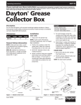
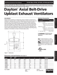
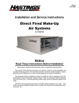
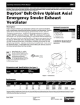
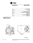
INSTALLATION
MAINTENANCE,
OPERATING
INSTRUCTIONS
IM-210
HOODED ROOF VENTILATORS
UPBLAST ROOF VENTILATORS
A WORD ABOUT SAFETY
AIR PRESSURE AND SUCTION
Air moving equipment involves electrical wiring, moving parts,
sound, and air velocity or pressure which can create safety
hazards if the equipment is not properly installed, operated and
maintained. To minimize this danger, follow these instructions
as well as the additional instructions and warnings on the
equipment itself.
In addition to the normal dangers of rotating machinery,
ventilators present another hazard from the suction created at
the inlet. This suction can draw materials into the propeller
where they become high velocity projectiles at the outlet. It can
also be extremely dangerous to persons in close proximity to
the inlet, as the forces involved can overcome the strength of
most individuals. Inlets that are not ducted should be screened
to prevent entry and discharge of solid objects.
All installers, operators and maintenance personnel should
study AMCA Publication 410, “Recommended Safety Practices
for Air Moving Devices”. Additional copies can be obtained by
writing to The New York Blower Company, 7660 Quincy Street,
Willowbrook, IL 60527.
ELECTRICAL DISCONNECTS
Every ventilator should have an independent disconnect switch
to isolate the unit from the electrical supply. It should be near
the unit and must be capable of being locked by maintenance
personnel while servicing, in accordance with OSHA
procedures.
MOVING PARTS
All moving parts must have guards to protect personnel. Safety
requirements vary, so the number and type of guards needed
to meet company, local and OSHA standards must be
determined and specified by the user. Never start a ventilator
without having all safety guards installed. Check regularly for
damaged or missing guards and do not operate with guards
removed. Ventilator propellers can also become dangerous
because of potential “windmilling”, even though all electrical
power is disconnected. Always block the rotating assembly
before working on any moving parts.
SOUND
Some fans can generate sound that could be hazardous to
exposed personnel. It is the responsibility of the system
designer and user to determine sound levels of the system, the
degree of personnel exposure, and to comply with applicable
safety requirements to protect personnel from excessive noise.
Consult nyb for fan sound power level ratings.
RECEIVING AND INSPECTION
The roof ventilator and accessories should be inspected on
receipt for any shipping damage. Turn the propeller by hand to
see that it rotates freely and does not bind. If a back draft
damper is provided, check this accessory for free operation of
all moving parts.
F.O.B. factory shipping terms require that the receiver be
responsible for inspecting the equipment upon arrival. Note
damage or shortages on the Bill of Lading and file any claims
for damage or loss in transit. nyb will assist the customer as
much as possible; however, claims must be originated at the
point of delivery.
HANDLING AND STORAGE
Ventilators should be lifted by the base using a platform or with
a sling. Never lift the unit by the propeller, shaft, motor, motor
bracket, housing inlet, outlet, or any part not designed for
lifting. A spreader should always be used to avoid damage.
Whenever possible, ventilators and accessories should be
stored in a clean, dry location to prevent damage. If outdoor
storage is necessary, protection should be provided. Cover the
inlet and outlet to prevent the accumulation of dirt and
moisture in the housing. Cover motors with waterproof
material. Refer to the bearing section for further storage
instructions.
Check back draft dampers for free operation and lubricate
moving parts prior to storage. Inspect the stored unit
periodically. Rotate the propeller by hand every two weeks
to redistribute grease on internal bearing parts.
VENTILATOR INSTALLATION
nyb propellers are dynamically balanced when fabricated.
Complete units are test run at the operating speed to check
the entire assembly for conformance to nyb vibration limits.
Nevertheless, all units must be adequately supported for
smooth operation. Ductwork should be independently
supported, as excess weight may distort the housing and
cause contact between moving parts.
Important: This method is only valid when the width of the
surface between the belt edge and the sheave face is the
same for both sheaves. When they are not equal, or when
using adjustable-pitch sheaves, adjust so that all belts have
approximately equal tension. Both shafts should be at right
angles to the center belt.
Belt Tensioning
1.
Check belt tension with a tensioning gage and adjust using
the motor slide base. Insufficient tension shortens belt life,
can reduce unit performance and may cause vibration.
Excess tension shortens bearing life. The lowest allowable
tension is that which prevents slippage under full load.
Belts may slip during start-up, but slipping should stop as
soon as the ventilator reaches full speed. For more precise
tensioning methods, consult the drive manufacturer’s
literature.
2.
Recheck setscrews, rotate the drive by hand and check for
rubbing, then complete the installation of all guards.
3.
Belts tend to stretch somewhat after installation. Recheck
tension after several days of operation. Check sheave
alignment, as well as setscrew and/or bushing bolt tightness.
Roof ventilators are designed for mounting on curbs. Curbs
should be constructed to support the weight of the unit and
accessories. Roof curbs supplied by nyb are
recommended. Curb tops should be level with ample
material for fastening to the unit.
Move the ventilator to its mounting location and lower it
over the curb. Tap the base until the unit rests flat on the
curb.
A minimum of eight (8) lag screws - two on each side - near
corners, are required to fasten the ventilator to the curb.
Neoprene washers and flat washers are recommended for
leak integrity. Tighten all screws securely.
Guy wire bracing must be provided when necessary on
large units to prevent side sway.
START-UP
Safe operation and maintenance includes the selection and
use of appropriate safety accessories for the specific installation. This is the responsibility of the system designer and
requires consideration of equipment location and accessibility as
well as adjacent components. All safety accessories must be
installed properly prior to start- up.
Safe operating speed is a function of system temperature and
propeller design. Do not under any circumstances exceed the
maximum safe unit speed.
Figure 1
Procedure
V-BELT DRIVE
Installation - Non-packaged Units/Replacement
1.
Remove all foreign material from the ventilator and motor
shafts. Coat shafts with machine oil for easier mounting.
2.
Mount sheaves on shafts after checking sheave bores and
bushings for nicks or burrs. Avoid using force. If
resistance is encountered, lightly polish the shaft with
emery cloth until the sheave slides on freely.
3.
Adjust the motor on its base to a position closest to the
ventilator shaft. Install belts by working each one over the
sheave grooves until all are in position. Never pry the
belts into place. Sufficient motor adjustment is provided
for easy installation of the proper size belts.
4.
Adjust the sheaves and the motor shaft angle so that the
sheave faces are in the same plane. Check this by placing
a straightedge across the faces of the sheaves. Any gap
between the edge and sheave faces indicates misalignment
1. If the drive components are not supplied by nyb, verify with
the manufacturer that the starting torque is adequate for the
speed and inertia of the propeller.
2. Inspect the installation prior to starting. Check for any
loose items or debris that could be drawn into the
ventilator or dislodged by the discharge. Check the interior
of the housing as well. Turn the propeller by hand to
check for binding.
3. Check the drive installation and belt tension.
4. Check the tightness of all setscrews, nuts and bolts. When
furnished, tighten hub setscrews.
5. Install all remaining safety devices and guards. Verify that
the supply voltage is correct and wire the motor. “Bump”
the starter to check for proper rotation.
6. Setscrews should be rechecked after a few minutes, eight
hours and two weeks of operation (see Table 1 for correct
tightening torques).
NOTE: Shut the ventilator off immediately if there is
any sudden increase in vibration.
Page 2
PROPELLER SETSCREW TORQUES
Setscrew Size
Diameter (in.)
1/4
5/16
3/8
7/16
1/2
The soundness of all parts should be determined if the original
thickness of components is reduced. Be sure there is no
hidden structural damage. The airstream components should
also be cleaned to remove any build-up of foreign material.
Specialized equipment can be used to rebalance a cleaned
propeller that is considered structurally sound.
Carbon Steel Setscrew Torque
lb.-in.
75
144
252
396
600
lb.-ft.
6.2
12
21
33
50
Balance weights should be rigidly attached at a point that will
not interfere with the housing nor disrupt airflow. Remember
that centrifugal forces can be extremely high at the outer radius
of a propeller blade.
Table 1
VENTILATOR MAINTENANCE
BEARINGS
nyb ventilators are manufactured to high standards with quality
materials and components. Proper maintenance will ensure a
long and trouble -free service life.
Do not attempt any maintenance on a ventilator unless the
electrical supply has been completely disconnected and
locked. In many cases, the propeller can windmill despite
removal of all electrical power. The rotating assembly should
be locked securely before attempting maintenance of any kind.
The key to good maintenance is regular and systematic
inspection of all parts. Inspection frequency is determined by
the severity of the application and local conditions. Strict
adherence to an inspection schedule is essential.
Regular maintenance should include the following:
1. Check the propeller for any wear or corrosion, as either
can cause catastrophic failures. Check also for the build-up
of material which can cause imbalance resulting in
vibration, bearing wear and serious safety hazards. Clean
or replace the propeller as required.
2. Check the V-belt drive for proper alignment and tension
(see section on V-belt drives). If belts are worn, replace
them as a set, matched to within manufacturer’s tolerances.
3. Ventilators with standard captured bearings in formed
housing require no service. Units with optional pillow block
bearings have grease fittings. These bearings should be
lubricated as specified in the bearing section. Do not over
lubricate.
4. During any routine maintenance, all setscrews and bolts
should be checked for tightness. See the table for correct
torques.
Storage
Any stored bearing can be damaged by condensation caused
by temperature variations. Therefore, nyb bearings are filled
with grease at the factory to exclude air and moisture. Such
protection is adequate for shipment and subsequent immediate
installation. Rotate the propeller by hand at least every two
weeks to redistribute grease on internal bearing parts.
Ventilators with standard captured bearings in formed metal
housing require no service.
Ventilators with optional pillow block bearings should be
purged with new grease to remove condensation, since even a
filled bearing can accumulate moisture. Use caution when
purging, as excessive pressure can damage the seals. Rotate
the shaft while slowly adding grease.
Operation - Optional Pillow block bearings
Check setscrew torque before start-up. Since bearings are
completely filled with grease at the factory, they may run at an
elevated temperature during initial operation. Surface temperatures may reach 180°F. and grease may bleed from the
bearing seals. This is normal and no attempt should be made
to replace lost grease. Bearing surface temperatures will
decrease when the internal grease quantity reaches a normal
operating level. Relubrication should follow the recommended
schedule.
Lubrication - Optional pillow block bearings
Use the table for relubrication scheduling according to operating speed and shaft diameter. Bearings should be lubricated
with a premium quality lithium-based grease conforming to
NLGI Grade 2. Examples are:
Mobil
Texaco
Chevron
Shell
5. When installing a new propeller, it should be positioned in
the housing with equal spacing between the edge of the
orifice and the propeller blade tips.
PROPELLER BALANCE
-
Mobilgrease XHP
Premium RB
Amolith #2
Alvania #2
Do not use “high temperature” greases, as many are not formulated to be compatible with fan bearings.
Airstreams containing particulate or chemicals can cause
abrasion or corrosion of ventilator parts. This wear is often
uneven and can lead to significant propeller unbalance over
time. When such wear is discovered, the decision must be
made to rebalance or to replace the propeller.
Add grease to the bearing while rotating the shaft by hand.
Add just enough grease to cause a slight purging at the seals.
Do not over lubricate.
Page 3
BEARING LUBRICATION INTERVAL [months]
Replacement
RPM
Shaft
1- 1 000
1001 -2000
6
5-6
5/8” - 1”
If captured bearings need replacement, install new bearings
into neoprene rings, check correct position of propeller with
orifice, position bearings in die-formed recess and tighten
setscrews. Replace die-formed bearing cap and tighten four
bolts.
Sealmaster, McGill, Link-Belt and SKF.
NOTE:
1. These are general recommendations only; specific
manufacturer’s recommendations may vary slightly.
2. Assumes clean environment, -20°F. to 120°F.
a.
b.
c.
3.
Consult The New York Blower Company for operation below -20°F. ambient.
Ambient temperatures greater than 120°F. will
shorten bearing life.
Under extremely dirty conditions, lubricate more
frequently.
If locking collar type bearing is used, collar must first be
positioned against inner race on bearing nearest propeller and
turned in direction of propeller rotation with drift pin and
hammer until it locks. Locking collars must be on inboard
(facing) sides of the bearings. Secure bearing to shaft with
setscrew. Lock and secure other bearing to shaft in same
manner.
Assumes horizontal mounting configuration. For vertically mounted applications, lubricate twice as frequently.
COMMON VENTILATOR PROBLEMS
Excessive Vibration
Excessive Noise
A common complaint regarding industrial ventilators is “excessive vibration”. nyb is careful to ensure that each unit is precisely balanced prior to shipment; however, there are many
other causes of vibration including:
1. Ventilator operating near “stall” due to incorrect system
design or installation.
2. Vibration originating elsewhere in the system.
3. System resonance or pulsation.
4. Improper location or orientation of intake and discharge.
5. Inadequate or faulty design of supporting structures.
6. Nearby sound reflecting surfaces.
7. Loose accessories or components.
8. Loose drive belts.
9. Worn bearings.
1.
2.
3.
4.
5.
6.
7.
Loose mounting bolts, setscrews, or bearings.
Misalignment or excessive wear of bearings.
Misaligned or unbalanced motor.
Bent shaft due to mishandling or material impact.
Accumulation of foreign material on the propeller.
Excessive wear or erosion of the propeller.
Excessive system pressure or restriction of airflow due to
closed dampers.
8. Inadequate structural support, mounting procedures or
materials.
9. Externally transmitted vibration.
Inadequate Performance
1.
2.
3.
4.
5.
Incorrect testing procedures or calculations.
Ventilator running too slowly.
Propeller rotating in wrong direction.
Propeller not properly centered relative to inlet.
Poor system design, closed dampers, air leaks, clogged
filters, or bird screens, snow.
6. Obstructions or sharp elbows near inlets.
7. Sharp deflection of airstream at outlet.
Premature Component Failure
1. Prolonged or major vibration.
2. Inadequate or improper maintenance.
3. Abrasive or corrosive elements in the airstream or
surrounding environment.
4. Misalignment or physical damage to rotating components
or bearings.
5. Bearing failure from incorrect or contaminated lubricant.
6. Excessive speed.
7. Extreme ambient or airstream temperatures.
8. Improper belt tension.
9. Improper tightening of propeller setscrews.
Page 4
LIMITED PRODUCT WARRANTY
All products are warranted by nyb to be free from defects in
materials and workmanship for a period of one (1) year after
shipment from its plant, provided buyer demonstrates to
satisfaction of nyb that the product was properly installed and
maintained in accordance with nyb's instructions and
recommendations and that it was used under normal operating conditions.
This warranty is limited to the replacing and/or repairing by
nyb of any part or parts which have been returned to nyb with
nyb's written authorization and which in nyb 's opinion are
defective. Parts not manufactured by nyb but installed by nyb
in equipment sold to the buyer shall carry the original
manufacturer’s warranty only. All transportation charges and
any and all sales and use taxes, duties, imports or excises for
such part or parts shall be paid for by the buyer. nyb shall
have the sole right to determine whether defective parts shall
be repaired or replaced.
This warranty does not cover any product which, in the
judgement of nyb, has been subject to misuse or neglect, or
which has been repaired or altered outside nyb's plant in any
way which may have impaired its safety, operation or
efficiency, or any product which has been subject to accident.
This warranty shall be null and void if any part not manufactured or supplied by nyb for use in any of its products
shall have been substituted and used in place of a part manufactured or supplied by nyb for such use.
There are no warranties, other than those appearing on the
acknowledgement form INCLUDING NO WARRANTY OF
MERCHANTABILITY OR FITNESS FOR A PARTICULAR
PURPOSE, given in connection with the sale of the goods sold
hereunder. The buyer agrees that his sole and exclusive
remedy, and the limit of nyb's liability for loss from any cause
whatsoever, shall be the purchase price of the goods sold
hereunder for which a claim is made.
This warranty does not cover any customer labor charges for
replacement of parts, adjustments or repairs, or any other
work unless such charges shall be assumed or authorized in
advance, in writing, by nyb.
The New York Blower Company - 7660 Quincy Street - Willowbrook, Illinois 60527-5530
HOODED ROOF VENTILATOR
1.
2.
3.
4.
5.
6.
7.
8.
Page 5
Parts List
Hood
Bird Screen
Shaft
Bearings
Disconnect Switch
Frame & Orifice Assembly
Propeller
Curb Cap Assembly
UPBLAST ROOF VENTILATOR
MODEL L
Parts List
1. Wind Band
2. Butterfly Damper
3. Propeller
4. Housing
5. Motor Base
6. Motor
7. Shaft and Bearing Assembly
8. Bearing Cap
9. Orifice
10. Sheaves
11. Motor Weather Cover
12. V-Belts
REPLACEMENT PARTS
It is recommended that only factory-supplied replacement parts
be used. nyb parts are built to be fully compatible with the
original equipment, using specific alloys and tolerances. These
parts carry a standard nyb warranty.
When ordering replacement parts, specify the part name, nyb
shop control number, ventilator size, type, arrangement and
bearing size or bore. Most of this information is on the nameplate attached to the ventilator base.
Example: Part required: Propeller
Shop/control number: B-10106-100
Description: Size L36
Suggested spare parts include:
Propeller
Component Parts: Motor
Shaft
Sheaves
Bearings
V-Belts
Form 807 GAW
Page 6