1
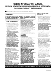
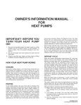
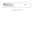
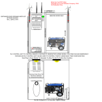
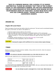
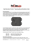
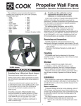
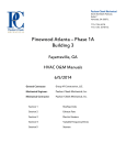
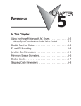
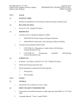
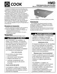
AC
Centrifugal Roof and Wall Exhausters
®
INSTALLATION, OPERATION AND MAINTENANCE
This publication contains the installation, operation and
maintenance instructions for standard units of the ACCentrifugal Roof and Wall Exhausters.
• ACE-D / ACE-B
• ACW-D / ACW-B / ACW-HP / ACW-XP
• ACRU-D / ACRU-B / ACRU-HP / ACRU-XP
Carefully read this publication and any
supplemental documents prior to any
installation or maintenance procedure.
Loren Cook AC catalog provides additional information
describing the equipment, fan performance, available
accessories, and specification data.
For additional safety information, refer to AMCA
publication 410-96, Safety Practices for Users and Installers
of Industrial and Commercial Fans.
All of the publications listed above can be obtained from
Loren Cook Company by phoning (417)869-6474,
extension 166; by FAX at (417)832-9431; or by e-mail at
[email protected].
For information and instructions on special equipment,
contact Loren Cook Company at 417.869-6474.
Handling
Lift the fan by the shipping
carton or lifting lugs provided
under top cap. NOTICE! Never
lift by the shaft, motor or
housing.
Storage
If the fan is stored for any
length of time prior to installation,
store it in its original shipping
crate and protect it from dust,
debris and the weather.
Lifting Lugs
Installation
If the fan was delivered with the motor unmounted, see
the maintenance section for belt and pulley installation.
If the fan was purchased as a wall mount unit and a
grease terminator or grease trough was not purchased, a 11/16 inch diameter drain hole should be drilled at the bottom
side of the fan for drainage.
Code requirements and environmental effects
Rotating Parts & Electrical Shock Hazard:
Disconnect electric power before working on unit.
Follow proper lockout / tagout procedures to ensure
the unit cannot be energized while being installed or
serviced.
A disconnect switch should be placed near the fan in
order that the power can be swiftly cut off, in case of
an emergency and in order that maintenance
personnel are provided complete control of the power
source.
Grounding is required. All field-installed wiring must
be completed by qualified personnel. All fieldinstalled wiring must comply with National Electric
Code (NFPA 70) and all applicable local codes.
Failure to follow these instructions could result in
death or serious injury.
Receiving and Inspection
Immediately upon receipt of an AC fan, carefully inspect
the fan and accessories for damage and shortage.
• Turn the wheel by hand to ensure it turns freely and
does not bind.
• Check dampers (if included) for free operation of all
moving parts.
• Record on the Delivery Receipt any visible sign of
damage.
The attachment of roof mounted fans to the roof curb
as well as the attachment of roof curbs to the building
structure must exceed the structural requirements
based on the environmental loading derived from the
applicable building code for the site. The local code
official may require variations from the recognized
code based on local data. The licensed engineer of
record will be responsible for prescribing the correct
attachment based on construction materials, code
requirements and environmental effects specific to
the installation.
Failure to follow these instructions could result in
death or serious injury.
Wall Exhauster Installation
the ventilator base to the motor compartment. For
external wiring, run the wires through the horizontal
conduit on upblast units, or under top cap in downblast
units.
3. Pull the wires through and complete the wiring.
If your fan is a wall exhauster, a mounting template is
shipped with the fan. Use the template to locate the
necessary lag screws or anchor bolts on the wall. The fan
can then be lifted and attached easily. Secure with lag
screws, anchor bolts, or other suitable fasteners.
Single Speed, Single Phase Motor
Damper Installation
When ground is required, attach to ground A or
B with no. 6 thread forming screw. To reverse,
interchange T-1 and T-4.
Ground A
If your fan is supplied with dampers, follow the directions
below. If your fan does not include dampers, proceed to
Belt and Pulley Installation.
1. Place the damper inside the curb or inside the duct
work. Ensure the damper will open freely for the correct
direction of the airflow.
2. Secure to curb at the damper shelf.
3. Drill hole in the curb shelf for conduit needed for motor
wiring.
4. Operate the dampers manually to ensure the blades
move freely.
5. Install fan over curb while aligning the conduit location
with the conduit hole in the curb.
L1
T-1
Line
T-4
L2
Ground B
2 Speed, 2 Winding, Single Phase Motor
When ground required,
attach to ground A or B
with No. 6 thread forming
screw. To reverse, interL1
change T-1 and T-4
Line leads.
L2
Ground A
High Speed
T-1
T-4
Low Speed
Ground B
Wiring Installation
Single Speed, Single Phase, Dual Voltage
NOTICE! All wiring should be in accordance
with local ordinances and the National Electrical
Code, NFPA 70. Ensure the power supply
(voltage, frequency, and current carrying
capacity of wires) is in accordance with the
motor nameplate.
(See page 3 for diagram)
Ground A
Ground A
L1
Link A
T-5
Link B
J-10
Line
Low Voltage
Link A & B
T-5
L1
Line
J-10
L2
L2
Ground B
Ground B
When ground required, attach to ground A or B with No. 6 thread forming screw. To
reverse, interchange T-5 and J-10 leads.
Upblast units have two wiring conduits. The vertical
conduit comes plugged. The horizontal conduit is directly
above the vertical conduit
For Units Without A Junction Box:
An approved metal field wiring compartment must be
secured to the unit with two screws in order that the box
does not rotate. All wires must be protected from abrasion
where they enter and exit the wiring compartment. The
green ground wire from the motor must be secured under
the green ground screws inside the field wiring compartment
using a closed loop connector. Complete connections in
accordance with the wiring diagram on the motor.
3 Phase, 9 Lead Motor
Y-Connection
3 Phase, 9 Lead Motor
Delta-Connection
Low Voltage
208/230 Volts
Low Voltage
208/230 Volts
9
8
7
5
4
6
3
2
1
4 5 6
High Voltage
460 Volts
4 5 6
7 8 9
1
7
2 3
8 9
L1 L2 L3
1 2
3
L1 L2 L3
L1
L2
L3
High Voltage
460 Volts
7 8 9
4 5 6
1 2 3
L1 L2 L3
To reverse, interchange any 2 line leads.
2 Speed, 2 Winding, 3 Phase
For Units With A Junction Box:
Pull wires through the appropriate conduit. Protect wires
from abrasion where they enter the field wiring compartment
and complete connections in accordance with the diagram
on the motor.
Leave enough slack in the wiring to allow for motor
movement when adjusting belt tension. Some fractional
motors have to be removed in order to make the connection
with the terminal box at the end of the motor.
To reverse: High Speed-interchange leads T11 and T12.
Low Speed-interchange leads T1 and T2. Both Speeds-interchange any 2 line leads.
NOTICE! Follow the wiring diagram in the disconnect
switch and the wiring diagram provided with the motor.
Correctly label the circuit on the main power box and
always identify a closed switch to promote safety (i.e.,
red tape over a closed switch).
1. Remove the top cap which covers the motor assembly
by unlatching the snap clips.
2. For internal wiring, run the electrical wire and conduit
through the opening drilled in the damper shelf (refer to
Damper Installation), then through the wiring conduit in
2
7. Ensure fan and ductwork are clean and free of debris.
8. Close and secure all access doors.
9. Restore power to fan.
Typical Damper Motor Schematic
L3
L2
L1
Fan
Motor
Transformer**
Damper
Motor*
Start-up
Turn on the fan. In variable speed units, set the fan to its
lowest speed. Inspect for the following:
• Direction of rotation
• Excessive vibration
• Unusual noise
• Bearing noise
• Improper belt alignment or tension (listen for squealing)
• Improper motor amperage or voltage
If a problem is discovered, immediately shut the fan
off. Lock out all electrical power and check for the cause
of the trouble. Refer to Troubleshooting on page 6.
Transformer**
Second
Damper
Motor
For 3 phase, damper motor voltage should be the same between L1 and L2.
For single phase application, disregard L3. *Damper motors may be available
in 115, 230 and 460 volt models. The damper motor nameplate voltage
should be verified prior to connection. ** A transformer may be provided in
some installations to correct the damper motor voltage to the specified voltage.
Inspection
Final Installation Steps
Inspection of the fan should be conducted at the first 30
minute, 8 hour and 24 hour intervals of satisfactory
operation. During the inspections, stop the fan and inspect
as instructed.
1. Ensure fasteners and set screws, particularly fan
mounting and bearing fasteners are tightened according
to the recommended torque shown on the table below.
2. Inspect for correct amperage with an ammeter and
correct voltage with a voltmeter.
3. Ensure that all accessories are installed.
4. Test the fan to be sure the rotation is the same as
indicated by the arrow marked ‘Rotation’.
NOTICE! Do not allow the fan to run in the wrong
direction. This will overheat the motor and cause
serious damage. For 3-phase motors, if the fan is
running in the wrong direction, check the control
switch. It is possible to interchange two leads at this
location so that the fan is operating in the correct
direction.
5. Inspect wheel-to-inlet clearance. Wheels may shift in
shipment. To realign wheel-to-inlet, shift upper bearing
so there is an equal radial clearance between the wheel
and inlet. Refer to wheel to inlet clearance on page 6.
Recommended Torque for Setscrews/Bolts (IN/LB)
Size
No.10
1/4”
5/16”
3/8”
7/16”
1/2”
5/8”
3/4”
Setscrews
Recommended
Torque Inch-lbs.
Key Hex
Across
Flats
Min.
Max.
3/32”
1/8”
5/32”
3/16”
7/32”
1/4”
5/16”
3/8”
28
66
126
228
348
504
1104
1440
33
80
156
275
384
600
1200
1800
30 Minute Interval
Inspect bolts, setscrews, and motor mounting bolts. Adjust
and tighten as necessary.
8 Hour Interval
Inspect belt alignment and tension. Adjust and tighten as
necessary.
24 Hour Interval
Inspect belt tension. Adjust and tighten as necessary.
Maintenance
Establish a schedule for inspecting all parts of the fan. The
frequency of inspection depends on the operating conditions
and location of the fan.
Inspect fans exhausting corrosive or contaminated air
within the first month of operation. Fans exhausting
contaminated air should be inspected every three months.
Regular inspections are recommended for fans exhausting
non-contaminated air.
Hold Down Bolts
Size
3/8”-16
1/2”-13
5/8”-11
3/4”-10
7/8”-9
1”-8
1-1/8”-7
1-1/4”-7
Regular inspections of the Grease Terminator 2 are
recommended. Depending on the amount of grease
discharged through the fan, the Grease Terminator 2 should
be changed every 30 to 45 days to ensure proper operation.
Any buildup of grease is easily seen during a visual
inspection of the clear canister. However, if the Grease
Terminator 2 becomes saturated, grease will no longer be
absorbed.
It is recommended the following inspections be conducted
twice per year.
Wrench
Torque (inchlbs)
240
600
1200
2100
2040
3000
4200
6000
• Inspect bolts and setscrews for tightness. Tighten as
necessary. Refer to Torque chart.
• Inspect belt wear and alignment. Replace worn belts with
new belts and adjust alignment as needed. Refer to Belt
and Pulley Installation, page 4.
• Bearings should be inspected as recommended in the
Conditions Chart.
• Inspect for cleanliness. Clean exterior surfaces only.
Removing dust and grease on motor housing assures
proper motor cooling.
Operation
1. Lock out all the primary and secondary power sources.
2. Inspect and tighten fasteners and setscrews, particularly
fan mounting and bearing fasteners Refer to Torque
chart.
3. Inspect belt tension and pulley alignment. Refer to Belt
and Pulley Installation, page 4.
4. Inspect motor wiring. Refer to Wiring Installation.
5. Ensure belt touches only the pulleys.
6. Rotate the wheel to ensure it rotates freely.
3
Fan Bearings
For motors with provisions for relubrication, follow
intervals of the table below.
Relubrication Intervals
NOTICE! The fan bearings are provided
prelubricated. Any specialized lubrication instructions
on fan labels supersedes information provided herein.
Bearing grease is a petroleum lubricant in a lithium
base conforming to a NLGI #2 consistency. If user
desires to utilize another type of lubricant, they take
responsibility for flushing bearings and lines, and
maintaining a lubricant that is compatible with the
installation.
A NLGI #2 grease is a light viscosity, low-torque, rustinhibiting lubricant that is water resistant. Its temperature
range is from -30°F to 200°F and capable of intermittent
highs of 250°F.
Bearings should be relubricated in accordance with the
condition chart below.
Service
Conditions
Standard
Severe
NOTICE! Motors are provided with a polyurea mineral
oil NGLI #2 grease. All additions to the motor bearings
are to be with a compatible grease such as Exxon Mobil
Polyrex EM and Chevron SRI.
The above intervals should be reduced to half for vertical
shaft installations.
Motor Services
Should the motor prove defective within a one-year period,
contact your local Loren Cook representative or your nearest
authorized electric motor service representative.
Conditions Chart
RPM
Up to 1000
1000 to 3000
Over 3000
Any Speed
Any Speed
Temp °F
-30 to 120
120 to 200
-30 to 120
120 to 200
-30 to 120
120 to 200
< -30
> 200
NEMA Frame Size
Up to and
213T-365T
404T and larger
including 184T
1800 RPM Over 1800 1800 RPM Over 1800 1800 RPM Over 1800
and less
RPM
and less
RPM
and less
RPM
3 yrs.
6 months
2 yrs.
6 months
1 yr.
3 months
1 yr.
3 months
1 yr.
3 months 6 months 1 months
Greasing Interval
6 months
2 months
3 months
1 month
1 month
2 weeks
Consult Factory
1 week
Changing Shaft Speed
All belt driven ventilators (5HP or less) are equipped with
variable pitch pulleys. To change fan speed, perform the
following:
1. Loosen setscrew on driver (motor) pulley and remove
key, if equipped.
2. Turn the pulley rim to open or close the groove facing. If
the pulley has multiple grooves, all must be adjusted to
the same width.
3. After adjustment, inspect for proper belt tension.
Maximum RPM with standard or reenforced wheel
For moist or otherwise contaminated installations; divide the interval by a
factor of 3. For vertical shaft installations divide the interval by a factor of 2.
For best results, lubricate the bearing while the fan is in
operation. Pump grease in slowly until a slight bead forms
around the bearing seals. Excessive grease can damage
seal and reduce life through excess contamination and/or
loss of lubricant.
In the event that the bearing cannot be seen, use no
more than three injections with a hand operated grease
gun.
ACE-B
ACRU-B &
ACRU-HP &
ACRU-XP
ACW-B
ACW-HP
&
Size Standard Reinforced Standard Reinforced Standard Reinforced ACW-XP
60
1981
70
1941
80
1806
100
2013
2002
120
1669
1671
135
1574
1574
150
1519
1520
1952
165
1296
1295
1728
2508
180
1513
1546
1829
2396
195
1348
1353
1570
2100
210
1190
1197
1626
2126
225
1043
1086
1435
1879
245
885
901
1185
1234
1616
270
752
766
1025
1049
1656
300
837
861
837
877
980
1046
1391
330
716
734
716
748
830
912
1182
365
624
648
624
659
735
872
1132
402
539
550
539
560
445
463
465
463
473
490
360
396
360
403
540
347
401
-
Motor Bearings
Motors are provided with prelubricated bearings. Any
lubrication instructions shown on the motor nameplate
supersede instructions below.
Direct Drive 1050/1075,1200,1300 &1500 rpm units use a
prelubricated sleeve bearing that has a oil saturated
wicking material surrounding it. The initial factory lubrication
is adequate for up to 10 years of operation under normal
conditions. However, it is advisable to add lubricant after 3
years. Use only LIGHT grade mineral oil or SAE 10W oil up
to 30 drops. If the unit has been stored for a year or more it
is advisable to lubricate as directed above. For units in
severe conditions, lubrication intervals should be reduced
to half.
Motors without sleeve bearings (as described above) will
have grease lubricated ball or roller bearings. Motor
bearings without provisions for relubrication will operate up
to 10 years under normal conditions with no maintenance.
In severe applications, high temperatures or excessive
contaminates, it is advisable to have the maintenance
department disassemble and lubricate the bearings after 3
years of operation to prevent interruption of service.
Speed Reduction:
Open the pulley in order that the belt rides deeper in the
groove (smaller pitch diameter).
Speed Increase:
Close the pulley in order that the belt rides higher in the
groove (larger pitch diameter). Ensure that the RPM limits of
the fan and the horsepower limits of the motor are
maintained.
4
Replacing Pulleys and Belts
Pulley Alignment
1. Clean the motor and fan shafts.
2. Loosen the motor plate mounting bolts to relieve the belt
tension. Remove the belt.
3. Loosen the pulley setscrews and remove the pulleys
from the shaft. If excessive force is required to remove
the pulleys, a three-jaw puller can be used. This tool,
however, can easily warp a pulley. If the puller is used,
inspect the trueness of the pulley after it is removed
from the shaft. The pulley will need replacement if it is
more than 0.020 inch out of true.
4. Clean the bores of the pulleys and place a light coat of
oil on the bores.
5. Remove any grease, rust or burrs from pulleys.
6. Place the fan pulley on the fan shaft and the motor
pulley on the motor shaft. Damage to the pulleys can
occur when excessive force is used in placing the
pulleys on their respective shafts.
7. After the pulleys have been correctly placed back onto
their shafts, tighten the pulley setscrews.
Belt and Pulley Installation:
Belt tension is determined by the sound of the belts when
the fan is first started. The belts will produce a loud squeal,
which dissipates after the fan is operating at full capacity. If
belt tension is too tight or too loose, lost efficiency and
damage may occur.
Pulley alignment is adjusted by
loosening the motor pulley
setscrew and by moving the motor
pulley on the motor shaft.
Do not change the pulley pitch diameter to change tension.
The change will result in a different fan speed.
Figure 1
1/4
inc
h
1 fo
ot
Figure 3
Figure 2 indicates where to
measure the allowable gap for the
drive alignment tolerance. All
contact points (indicated by
WXYZ) are to have a gap less than
the tolerance shown in the table.
When the pulleys are not the same
width, the allowable gap must be
adjusted by half of the difference in width. Figure 3 illustrates
using a carpenter’s square to adjust the position of the motor
pulley until the belt is parallel to the longer leg of the square.
Bearing Replacement
The fan bearings are pillow block type ball bearings.
1. Remove the old bearing.
2. Remove any burrs from the shaft by sanding.
3. Slide new bearings onto the shaft to the desired location
and loosely mount bearings onto the bearing support.
Bearing bolts and setscrews should be loose enough to
allow shaft positioning.
4. Correctly position the wheel and tighten the bearing
bolts securely to the bearing support.
5. Align setscrews bearing to bearing and secure tightly to
the shaft.
NOTICE! Never tighten both pairs of setscrews
before securing bearing mounting bolts. This may
damage the shaft.
6. Inspect the wheel position again. If necessary, readjust
by loosening the bearing bolts and setscrews and
repeat from step 3.
Wheel Replacement
1. Loosen motor
Figure 2
plate adjustment Tolerance
Center Distance Maximum Gap
bolts and slide
Up thru 12”
1/16”
12 through 48”
1/8”
motor plate so
Over 48”
1/4”
that belts easily
OFFSET
ANGULAR
OFFSET/ANGULAR
slip into the
A
grooves on the
W
pulleys. Never
pry, roll, or force
the belts over the
rim of the pulley.
CENTER
DISTANCE
2. Slide motor plate X
(CD)
Y
until proper
tension is
reached. For
proper tension, a Z
B
GAP
GAP
deflection of
approximately 1/4” per foot of center distance should be
obtained by firmly pressing the belt. Refer to Figure 1.
3. Lock the motor plate adjustment bolts in place.
4. Ensure pulleys are properly aligned. Refer to Figure 2.
5
1. Drill two holes approximately centered between the
shaft and the edge of the hub OD with the following
dimensions:
• 1/4" diameter
• 3/8" to 1/2" deep
• 180° apart in face of hub
2. Tap 1/4" holes to 5/16" thread with the 5/16" hole tap.
Do not drill or tap any larger than recommended.
3. Screw the puller arms into the tapped holes full depth of
threads (3/8" to 1/2" approximately). Align center of
puller with center of shaft. Make certain all setscrews in
hub (normally a quantity of two) are fully removed. Work
puller slowly to back wheel off the shaft.
Troubleshooting
Recommended Puller:
Lisle No. 45000 Sterling Wheel Puller. This puller is available
at most automotive parts retail outlets.
Problem and Potential Cause
Low Capacity or Pressure
•Incorrect direction of rotation. Make sure the fan rotates in same direction
as the arrows on the motor or belt drive assembly.
•Poor fan inlet conditions. There should be a straight clear duct at the inlet.
•Improper wheel alignment.
Excessive Vibration and Noise
•Damaged or unbalanced wheel.
•Belts too loose; worn or oily belts.
•Speed too high.
•Incorrect direction of rotation. Make sure the fan rotates in same direction
as the arrows on the motor or belt drive assembly.
•Bearings need lubrication or replacement.
•Fan surge.
Above - Drilled hole placement.
Right - Wheel puller.
Wheel-to-Inlet Clearance
The correct wheel-to-inlet clearance is critical to proper
fan performance. This clearance should be verified before
initial start-up since rough handling during shipment could
cause a shift in fan components. Refer to wheel/inlet drawing for correct overlap.
Overheated Motor
•Motor improperly wired.
•Incorrect direction of rotation. Make sure the fan rotates in same direction
as the arrows on the motor or belt drive assembly.
•Cooling air diverted or blocked.
•Improper inlet clearance.
•Incorrect fan RPMs.
•Incorrect voltage.
Adjust the overlap by loosening the wheel hub and moving the wheel along the shaft to obtain the correct value.
A uniform radial gap (space between the edge of the
cone and the edge of the
inlet) is obtained by loosening the bearing bolts and
set screws which will allow
for correct repositioning.
Size
Overlap
60 - 165
3/16”
180 - 245
1/4”
270 - 300
5/16”
330 - 365
3/8”
402
7/16”
445 - 490
1/2”
540
13/16”
Overheated Bearings
•Improper bearing lubrication
•Excessive belt tension.
6
ACE-D Parts List
Part
No.
1a
1b
2
3
4
5
6
7
8
9
10
11
12
3
1
4
2
10
7
5
6
11
12
8
9
Sizes 70-100
1a
3
2
1b
4
10
5
7
6
12
11
8
9
Sizes 120-180
7
ACE-D Parts Description
70-100
Top Cap
—
Motor
Motor Plate
Baffle
Wheel Assembly
Bird Screen
Base
Conduit
Isolator (4)
Upper Post (4)
—
120-180
Top Cap Lid
Top Cap Cylinder
Top Cap Clip (4)
Motor
Motor Plate
Baffle
Wheel Assembly
Bird Screen
Base
Conduit
Isolator (4)
Upper Post (4)
Lower Post (4)
ACE-B Parts List
17
19
18
1a
16
2
15
1b
3
14
10
4
7
5
11
12
6
13
9
8
Part
No.
1a
1b
2
3
4
5
6
7
8
9
10
11
12
13
14
15
16
17
18
19
60-100
Top Cap Lid
Top Cap Cylinder
Top Cap Clip (4)
Motor
—
Baffle
Wheel Assembly
Bird Screen
Base
Conduit
Isolator (3)
Upper Post (4)
Lower Post (4)
—
Power Assembly
Shaft
Bearing (2)
Drive Sheave
Driven Sheave
Belt Set
8
ACE-B Parts Description
120-245
270-300
330-540
Top Cap Lid
Top Cap Lid
Top Cap Lid
Top Cap Cylinder Top Cap Cylinder Top Cap Cylinder
Top Cap Clip (4) Top Cap Clip (8) Top Cap Clip (8)
Motor
Motor
Motor
Motor Plate
Motor Plate
Motor Plate
Baffle
Baffle
Baffle
Wheel Assembly Wheel Assembly Wheel Assembly
Bird Screen
Bird Screen
Bird Screen
Base
Base
Base
Conduit
Conduit
Conduit
Isolator (4)
Isolator (4)
Isolator (4)
Upper Post (4)
Upper Post (8)
Upper Post (8)
Lower Post(4)
Lower Post (8)
Lower Post (8)
—
—
Brace (8)
Power Assembly Power Assembly Power Assembly
Shaft
Shaft
Shaft
Bearing (2)
Bearing (2)
Bearing (2)
Drive Sheave
Drive Sheave
Drive Sheave
Driven Sheave
Driven Sheave
Driven Sheave
Belt Set
Belt Set
Belt Set
ACW-D Parts List
ACW-D Parts Description
10
Part
No.
7
5
1a
1b
120-195
Top Cap Lid
Top Cap
1b
1a
9
8
70-100
Top Cap Cylinder
2
—
Top Cap Clip (4)
3
Motor
Motor
4
Motor Plate
Spun Motor Plate
5
Baffle
Baffle
6
Wheel Assembly
Wheel Assembly
7
Bird Screen
Bird Screen
8
Wall Flange
Wall Flange
9
Post (4)
Post (4)
10
Wind Band
Wind Band
11
—
Brace (4)
12
Grommet (2)
Grommet (2)
13
Vent Tube (angled)
Vent Tube
3
2
4
13
6
12
Sizes 70-100
10
7
5
11
1b
1a
9
8
3
2
6
4
13
12
Sizes 120-195
9
ACW-B Parts List
ACW-B Parts Description
4
2
Part
No.
100
120-165
180-245
1a
Top Cap Lid
Top Cap Lid
Top Cap Clip
15
1b
Top Cap Cylinder
Top Cap Cylinder
Top Cap Cylinder
3
2
Top Cap Clip (4)
Top Cap Clip (4)
Top Cap Clip (4)
17
3
Motor
Motor
Motor
4
Spun Motor Plate
Spun Motor Plate
Spun Motor Plate
5
Baffle
Baffle
Baffle
6
Wheel Assembly
Wheel Assembly
Wheel Assembly
7
Bird Screen
Bird Screen
Bird Screen
8
Wall Flange
Wall Flange
Wall Flange
9
Isolator (3)
Isolator (4)
Isolator (4)
10
Post (4)
Post (4)
Post (8)
11
Wind Band
Wind Band
Wind Band
12
—
Brace (4)
Brace (8)
13
Power Assembly
Power Assembly
Power Assembly
14
Shaft
Shaft
Shaft
15
Bearing (2)
Bearing (2)
Bearing (2)
16
Drive Sheave
Drive Sheave
Drive Sheave
17
Driven Sheave
Driven Sheave
Driven Sheave
18
Belt Set
Belt Set
Belt Set
19
Vent Tube
Vent Tube
Vent Tube
20
Grommet (2)
Grommet (2)
Grommet (2)
13
8
6
14
18
10
16
1a
1b
5
7
9
20
12 11
19
10
ACRU-D Parts List
1
3
13
9
4
10
15
5
16
6
7
11
8
ACRU-D Sizes 70 - 100
1a
ACRU-D Parts Description
Part
No.
1a
1b
2
3
4
5
6
7
8
9
10
11
12
13
14
15
16
70-100
Top Cap
—
Motor
Motor Plate
Baffle
Wheel Assembly
Bird Screen
Base
Conduit
Isolator (4)
Upper Post (4)
—
Wind Band
—
Vent Tube
Grommet (2)
120-195
Top Cap Lid
Top Cap Cylinder
Top Cap Clip (4)
Motor
Spun Motor Plate
Baffle
Wheel Assembly
Bird Screen
Base
Conduit
Isolator (4)
Upper Post (4)
Lower Post (4)
Wind Band
Brace (4)
Vent Tube
Grommet (2)
3
2
1b
16
13
15
9
4
10
5
14
6
11
7
12
8
ACRU-D Sizes 120 - 195
ACRU-B Parts List
Part
No.
1a
1b
2
3
4
5
6
7
8
9
10
11
12
13
14
15
16
17
18
19
20
21
22
1a
18 20 19
17
1b
2
15
3
16
22
10
13
21
9
5
4
6
14 11
9
12
7
8
11
100
Top Cap Lid
Top Cap Cylinder
Top Cap Clip (4)
Motor
Spun Motor Plate
Baffle
Wheel Assembly
Bird Screen
Base
Conduit
Isolator (3)
Upper Post (4)
Lower Post (4)
Wind Band
—
Power Assembly
Shaft
Bearing (2)
Drive Sheave
Driven Sheave
Belt Set
Vent Tube
Grommet (2)
ACRU-B Parts Description
120-245
Top Cap Lid
Top Cap Cylinder
Top Cap Clip (4)
Motor
Spun Motor Plate
Baffle
Wheel Assembly
Bird Screen
Base
Conduit
Isolator (4)
Upper Post (4)
Lower Post (4)
Wind Band
Brace (4)
Power Assembly
Shaft
Bearing (2)
Drive Sheave
Driven Sheave
Belt Set
Vent Tube
Grommet (2)
270-490
Top Cap Lid
Top Cap Cylinder
Top Cap Clip (8)
Motor
Spun Motor Plate
Baffle
Wheel Assembly
Bird Screen
Base
Conduit
Isolator (4)
Upper Post (8)
Lower Post (8)
Wind Band
Brace (8)
Power Assembly
Shaft
Bearing (2)
Drive Sheave
Driven Sheave
Belt Set
Vent Tube
Grommet (2)
Limited Warranty
Loren Cook Company warrants that your Loren Cook fan was manufactured free of defects in materials and workmanship, to the extent stated herein. For a period of one (1)
year after date of shipment, we will replace any parts found to be defective without charge, except for shipping costs which will be paid by you.
This warranty is granted only to the original purchaser placing the fan in service.
This warranty is void if the fan or any part thereof has been altered or modified from its original design or has been abused, misused, damaged or is in worn condition or if the
fan has been used other than for the uses described in the company manual. This warranty does not cover defects resulting from normal wear and tear.
To make a warranty claim, notify Loren Cook Company, General Offices, 2015 East Dale Street, Springfield, Missouri 65803-4637, explaining in writing, in detail, your complaint
and referring to the specific model and serial numbers of your fan. Upon receipt by Loren Cook Company of your written complaint, you will be notified, within thirty (30) days of
our receipt of your complaint, in writing, as to the manner in which your claim will be handled. If you are entitled to warranty relief, a warranty adjustment will be completed within
sixty (60) business days of the receipt of your written complaint by Loren Cook Company.
This warranty gives only the original purchaser placing the fan in service specifically the right. You may have other legal rights which vary from state to state.
For fans provided with motors, the motor manufacturer warrants motors for a designated period stated in the manufacturer’s warranty. Warranty periods vary from manufacturer
to manufacturer. Should motors furnished by Loren Cook Company prove defective during the designated period, they should be returned to the nearest authorized motor service station. Loren Cook Company will not be responsible for any removal or installation costs.
LOREN COOK COMPANY
Corporate Offices:
2015 E. Dale Street Springfield, MO 65803 417.869.6474
lorencook.com
12
AC IOM - December 2013