1
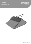
Operating Instructions for JHV-15C Series
Screen Area
Screen Selection Area
Direction Keypad
Number Keypad
Function Selection Area
Action Keypad
Table of Contents
0-1. Introduction for Data Set Items....................................................................................................... P.1
0-2. Introduction for Data Set Items....................................................................................................... P.2
0-3. Description for Number Key and Direction Key....................................................................... P.3
0-4. Description for Function Key........................................................................................................... P.3
0-5. Description for Manual Operating Key........................................................................................ P.4
1. Mold Close Screen.................................................................................................................................... P.6
2. Mold Open Screen.................................................................................................................................... P.7
3. Injection Screen
3-1. Injection Set Page.......................................................................... P.8
3-2. Injection/Pressure Curve Page......................................................................................................... P.9
4. Holding Screen........................................................................................................................................ P.10
5. Screw Screen............................................................................................................................................ P.11
6. Cooling Screen
Time/Count Set Page.......................................................................... P.12
7. Nozzle Screen
7-1. Nozzle Adv. / Ret.......................................................................... P.13
7-2. Nozzle Up / Down............................................................................................................................... P.14
8. Memory Screen....................................................................................................................................... P.15
9. Ejector Screen......................................................................................................................................... P.16
9-1. Instruction for Ejector Stroke........................................................................................................ P.17
9-2. Moved/Fixed Mold Air-Blast.......................................................................................................... P.18
10. Core Set................................................................................................................................................... P.19
11. Temperature Screen
11-1. Temperature Set Page............................................................ P.20
11-2. Preheating Time and Date Time Set.......................................................................................... P.21
12. Mold Transfer Screen 12-1. Mold Transfer / Turnplate Set............................................ P.22
12-2. Positioning Set................................................................................................................................... P.23
13. Setting for Mold Adjust..................................................................................................................... P.24
14. Function Screen
14-1. Function Set Page.................................................................... P.25
14-2. Time / Count Page............................................................................................................................ P.26
14-3. Data Protection Set.......................................................................................................................... P.27
14-4. Setting for Special Function Page............................................................................................... P.28
15. Production Screen
15-1. Setting for QC Monitoring Page........................................ P.29
15-2. Product Record Page...................................................................................................................... P.30
16. Monitoring Screen
16-1. Machine Monitoring Page.................................................... P.30
16-2. Monitoring for Input-Port............................................................................................................ P.31
16-3. Monitoring for Output-Port......................................................................................................... P.31
16-4. I/O Expansion.................................................................................................................................... P.32
16-5. Pointing Monitoring........................................................................................................................ P.33
17. Engineer Screen
17-1. Engineer Page................................................................... P.34
17-2. Setup Page of Direction Valve Delay......................................................................................... P.35
17-3. Setup Page of Proportion Valve Ramp-1................................................................................. P.36
17-4. Setup Page of Proportion Valve Ramp-2................................................................................. P.37
17-5. Lock-In Ruler Adjust Page........................................................................................................... P.38
17-6. Screen / Unit Selection.................................................................................................................... P.39
17-7. Adjust Pressure................................................................................................................................. P.40
17-8. Engineer Function Set 1................................................................................................................. P.41
17-9. Engineer Function Set 2................................................................................................................. P.42
0-1 Introduction for Data Set Items
: Press once to enter the machine dynamic screen.
: Press twice to enter the input monitoring screen.
: Press thrice to enter the output monitoring screen.
: Press four times to enter the expansion I/O monitoring screen.
: Press five times to enter the pointing monitoring screen.
: Press it into the mold close set screen.
: Press it into the mold open set screen.
: Press it into the nozzle set screen.
: Press once to enter the injection set screen.
: Press twice to enter the injection curve screen.
: Press it into the holding set screen.
: Press it into the screw set screen.
: Press it into the time / count set screen.
~1~
0-2 Introduction for Data Set Items
: Press once to enter the temperature set screen.
: Press twice to enter the preheating set screen.
: Press once to enter the core A set screen.
: Press twice to enter the core B set screen.
: Press once to enter the function set screen.
: Press twice to enter the time / count set screen.
: Press thrice to enter the data protection screen.
: Press it into the mold memory set screen.
: Press it into the QC monitoring set screen.
: Press twice to enter the product record screen.
: Press it into the mold-adjust set screen.
: Press it into the mold-transfer set screen.
: Press twice to enter the pointing set screen.
: Press it into the ejector set screen.
: Press twice to enter the moved / fixed mold air-blast set screen.
~2~
0-3 Description for Digit and Direction Key
Press it into the engineer set screen.
Note: the password should be entered.
The digital input key,
English letter desired can be
inputted for the second
time.
e.g.: Press once “4”
Press once “g”
Press once “h”
Press once “i”
When the number modified without confirming
by SET button flashes, press "REVERT" to
recover the previous setting value.
It is Help key.
Press it to add 1 or reduce 1 for
number. If holding press, the number
will be accumulative plus or minus.
Digital backlight adjustment
1. Press SET or “Shift” button for a new number
inputted. The number flashing means that need to set.
2. The SET button can be used as on/off to switch the
function.
The button is used for alarm reset when alarm is produced,
while the alarm records can be observed.
The key for cursor shift up, down, left or right
0-4 Description for Function Key
LED on, in the
manual status.
LED on, in the
semi-auto status.
LED on, in the
full-auto status.
LED on, the mold
adjust is in use.
LED on, the heater
has been started.
LED on, the motor
is running.
~3~
0-5 Description for Manual Operating Key
Mold Open Key: Press it to perform the mold open stroke.
Condition: The current position of moved mold shouldn’t exceed the setting position value of
mold-open-end.
Mold Close Key: Press it to perform the mold close stroke.
Condition: The front and back safety door (19, 23), the robot end signal (18) and the ejector
ret. end (10) should be ON, but the mold-close-end (07) and the proximity should
be OFF.
Injection Key: Press it to perform the injection 1.
Condition: The cylinder temperature should be up to the set value and the setting button of
heater should be ON.
Suck-Back Key: Press it to perform the suck-back stroke.
Condition: The cylinder temperature should reach the set value.
Eject Ret. Key: Press it to perform the ejector backward stroke.
Condition: The proximity (10) of ejector ret. end should be OFF.
Eject Adv. Key: Press it to perform the ejector forward stroke; the ejector action will go on if
holding press.
Condition: Start from the mold-open-end position and the proximity of ejector adv. end should
be OFF.
Nozzle Adv. Key: Press it to perform the unit forward stroke; the slow nozzle adv. will be
acted if meeting the proximity of nozzle adv. end.
Condition: The mold close is finished before the unit forward, and the mold-close-end (7)
should be ON.
Nozzle Ret. Key: Press it to perform the unit backward stroke.
Core Out Key: Press it to perform the core A out stroke.
Condition: Core A used should be selected, and the action mode and position should be set.
~4~
0-5 Description for Manual Operating Key
Core In Key: Press it to perform the core A in stroke.
Condition: Core A used should be selected, and the action mode and position should be set.
Screw Key: Press it to perform the screw stroke.
Condition: The cylinder temperature should reach the set value, the screw time should be set
and positioning.
Transfer Right Key: Press it, the mould will transfer right.
Condition: The eject ret. end should be ON, and the mold-open-end should be reached.
Transfer Left Key: Press it, the mould will transfer left.
Condition: The eject ret. end should be ON, and the mold-open-end should be reached.
Lock-In Key: The discal machine is started to use; press the button, the positioning dowel will
eject up.
Condition: The transfer left/right end should be ON.
Gate Open Key: Press it to perform the air-door open stroke.
Condition: Set the air-door function to ON.
Gate Close Key: Press it to perform the air-door close stroke.
Condition: Set the air-door function to ON.
~5~
1. Mold Close Screen
Code
Status
Scope
Description
A
Actual Value
0-999.9 mm
Display the current position for the displacement transducer
of moved mold.
B
Actual Value
0-99.9 sec
Display time for the action route of mold close.
C
Set Value
0-140 kg
The set value of pressure
D
Set Value
0-99%
E
Set Value
0-999.9 mm
The position of fast speed switching to mid speed when
closing mold.
F
Set Value
0-999.9 mm
The position of mid speed turning into low pressure when
closing mold.
G
Set Value
0-999.9 mm
The position of low pressure changeover hi-pressure in
closing mold, namely, the position of mold-close-end.
H
Set Value
0-99.9 sec
The pressure increased time is going on after the hi-pressure
reaches, then close the hi-pressure.
0-99.9 sec
Mold close reaches the low pressure position (F) and start to
time, and the hi-pressure position (G) should be reached in
the low pressure time, or else, “low pressure time is over” is
alarmed and mold open is up to the mold-open-end.
I
Set Value
The set value of speed
** Notes **
1. The distance of mold close should be set from large to small, then E>F>G action can run smoothly.
2. The low pressure of mold close shouldn’t be set beyond 10KG, and the low-pressure position exceeds the
hi-pressure one at least 50mm.
3. To set the high-pressure position, firstly set it to “0” after the mold adjust, then according to the mold close
stroke until the mold is so close that mold close could not continue. Here the position of moved mold is the
actual hi-pressure position. Thus, adding 0.5mm on it to input into the hi-pressure position.
~6~
2. Mold Open Screen
Code
Status
Scope
Description
A
Actual Value
0-999.9 mm
Display the current position for the displacement transducer
of moved mold.
B
Actual Value
0-99.9 sec
Display time for the action route of mold open.
C
Set Value
0-140 kg
The set value of pressure
D
Set Value
0-99%
E
Set Value
0-999.9 mm
It is the position of mold-open-end that should be below the
maximum open-distance (L). Otherwise, it can’t be inputted.
F
Set Value
0-999.9 mm
The position of mid speed switching to back slow when
opening mold.
G
Set Value
0-999.9 mm
The position of fast speed turning into mid speed in the
mold open.
H
Set Value
0-999.9 mm
The pressure increased time is going on after the hi-pressure
reaches, then close the hi-pressure.
0-999.9 mm
It is the maximum open-distance that is the longest
mold-open stroke, which is set by machinist before leaving
factory and can be changed in the engineer screen. The
mold-open-end (E) should be set below this value.
I
Show Value
The set value of speed
** Precautions **
1. Set the distance of mold open from small to large, E>F>G>H action then can run smoothly.
~7~
3. Injection Screen
3-1. Injection Set Page
Code
Status
Scope
Description
A
Actual Value
0-999.9 mm
Display the present position for the displacement transducer
of screw pole.
B
Actual Value
0-999.9 s
Display time for the action route of screw pole.
C
Actual Value
0-140 kg
Display the pressure sensor.
D
Set Value
0-140 kg
The set value of pressure.
E
Set Value
0-99%
F
Set Value
0-99.99 s
G
Set Value
0-999.9 mm
H
Set Value
0-999.9 mm
I
Set Value
0-999.9 mm
J
Set Value
0-999.9 mm
K
Actual Value
0-999.9 mm
L
Set Value
Time, Position
M
Set Value
0-140 kg
N
Set Value
0-99.99 s
O
Set Value
The set value of speed.
The injection action will be performed according to the set
time if Time is selected for the injection mode.
The position of injection 1 end changeover injection 2 start.
The injection 1 will not act if the value is set to “0”.
The position of injection 2 end changeover injection 3 start.
The injection 1 will not act if the value is set to “0”.
The position of injection 3 end changeover injection 4 start.
The injection 1 will not act if the value is set to “0”.
The position of injection 4 end changeover injection holding
start. The injection 1 will not act if the value is set to “0”.
Display the position of holding point.
Press SET button to change the options (Position and Time
is optional).
The set value 3 is the reference point when judging the
holding point with the pressure sensor.
It is the monitoring time from injection 1 to injection 4,
which should be set beyond the time of injection route.
Jump to the holding stroke when the injection time is over.
Press SET button to change the options:
R-P position is reference point of injection spillage.
Regard K as R before selecting:
R+Q position is reference point of injection shortage.
~8~
3-2. Injection / Pressure Curve Page
※ Provide shaping reference and display actual pressure and flow curve according to the set pressure value and
flow value shown by the curve in the injection curve screen.
~9~
4. Holding Screen
Code
Status
Scope
Description
A
Actual Value
0-999.9 mm
Display present position for the displacement transducer of
screw pole.
B
Actual Value
0-999.9 s
Display time for the action route of screw pole.
C
Set Value
0-140 kg
Display the pressure sensor.
D
Set Value
0-140 kg
The set value of pressure.
E
Set Value
0-99%
F
Set Value
0-99.99 s
Holding is performed by the set time. Don’t act if the value
is set to “0”.
G
Set Value
0-9.9 s
If it isn’t “0”, the pressure of this section will act by the up
ramp firstly, then perform the pressure speed of F set time.
The set value of speed.
Ramp Diagram of Injection Holding:
~10~
5. Screw Set Screen
Code
Status
Scope
Description
A
Actual Value
0-999.9 mm
Display present position for the displacement transducer of
screw pole.
B
Actual Value
0-999.9 s
C
Actual Value
0-99.9 RPM
Display the screw RPM, which can only be shown after the
screw rotating sensor is set up.
The maximum of screw distance that show the longest
screw route of machine, which is set by machinist before
leaving factory and can be changed in the engineer screen.
The screw end should be below this value.
Display time for the action route of screw pole.
D
Set Value
0-999.9 mm
E
Set Value
0-140 kg
F
Set Value
0-99%
G
Set Value
0-99.9 mm
At first, perform the front suck-back position after injection.
Generally, please set the position H to 0 if no use.
H
Set Value
0-999.9 mm
The position of screw 1 end changeover screw 2 start. Set
the value to 0 if the section 1 is only used for the screw.
I
Set Value
0-999.9 mm
The position of screw 2 end changeover post suck-back
start.
J
Set Value
0-999.9 mm
Position of suck-back distance again. The position of screw
end is I + J.
K
Show Value
The set value of pressure.
The set value of speed.
Suck-back after cooling when using. Cooling after
suck-back if no using.
~11~
6. Cooling Screen
Time / Count Set Page
Code
Status
Scope
Description
A
Set Value
0-999.9 sec
Perform the set cooling time after injection, then suck-back
and screw.
B
Set Value
0-999.9 sec
Perform the set cooling time after screw.
C
Set Value
0-999.9 sec
The same as the monitoring time of injection screen.
Perform holding once the accumulative injection time is
equal to injection time or monitoring time.
D
Set Value
0-999.9 sec
Display no stuff while the accumulative screw time is
beyond this set value.
E
Set Value
0-999.9 sec
The accumulative alarm time will appear when the machine
fails.
F
Set Value
0-99.9 sec
Time of increasing pressure will continue to perform after
the hi-pressure position reaches, then close the hi-pressure.
G
Set Value
0-999999 mold
The alarm “Production Doesn’t Go On” will appear while
the set counts of total production molds are produced.
The alarm “Continue To Produce Again” will appear while
reaching the subtotal counts of production molds are
produced.
H
Set Value
0-99999 mold
I
Set Value
0-99 counts
Set the times of screw.
J
Set Value
0-999.9 sec
The alarm occurs if accumulative time of cycle monitoring
is beyond this value.
K
Set Value
0-9.9 sec
Closing mold while delaying this set time between after the
previous 1 mold and before the next one.
~12~
7. Nozzle
Code
7-1. Nozzle Movement Set Page
Status
Scope
Description
Press SET button to switch over. Use: perform the nozzle
ret. after injection and suck-back are completed, then
perform the nozzle adv. waiting for the next mold close
finished.
A
Set Value
B
Set Value
0-140 kg
C
Set Value
0-99%
D
Set Value
0-99.9 sec
Adjust nozzle adv./ret. by time for the nozzle route while
using the nozzle movement.
Cooling End
Perform nozzle ret. stroke after timing screw-cooling is
finished while the nozzle movement.
Suck-Back End
Perform nozzle ret. stroke after screw suck-back is finished
but the cooling time reaching isn’t waited for while the
nozzle movement.
E
Set Value
The set value of pressure.
The set value of speed.
~13~
7-2. Nozzle Up/Down Set Page
Code
Status
Scope
Description
A
Set Value
ON/OFF
Press SET button to switch over. ON: In Manual Status:
press Nozzle Up button to perform the nozzle up; press
Nozzle Down button to perform the nozzle down.
B
Set Value
0-140 kg
The set value of pressure.
C
Set Value
0-99%
The set value of speed.
~14~
8. Memory Screen
* Note: 0 to 48 sets are savable inner of this computer, and with additionally optional memory
card is used for 50 to 99 sets.
Code
Status
Scope
A
Actual Value
0-99
Description
Display the serial number of mould used at present.
Display the name of mould used at present. Please refer to
appendix 1.4 for English input.
Display the mold number used at present and the date
Actual Value
Date
C
written of the time.
Display the memory screen that includes 19 pages, which to
Set
Value
0-19
pages
provide the contents switched by pressing plus/minus button
D
for user.
Set the serial number of mould desired to write in or read
Set Value
0-99
E
out.
Set the mould name desired to save. Keep in mind! Firstly
Set Value
0-9, A-Z
F
input the serial number of mould.
Save the current data into the memory------flow:
1. First confirm the current action parameter as saving value desired.
2. Observe if there is blank area left in the table of contents. ***49 sets are not savable, but the memory
card is needed for 50 to 99 sets. ***
3. If there is not blank area, the memory number isn’t selected for the cover mode, and the mould number
must be first confirmed.
4. After input mould number, the mould name can be edited; If haven’t the names, can also written in or
read out.
Flow:
B
Actual Value
0-9, A-Z
~15~
9. Ejector Screen
Code
Status
Scope
A
Set Value
ON/OFF
B
Actual Value
0-999.9 mm
C
Set Value
0-140 kg
D
Set Value
0-99%
E
Set Value
0-99.9 sec
Time of ejector forward/backward
F
Set Value
0-99.9 sec
Set the delay time before the ejector forward/backward acts.
G
Set Value
0-99 counts
Count the ejector times, serial ejector and oscillating ejector
according to this set value.
H
Set Value
ON/OFF
Serial Ejector
Description
Press SET button to switch over.
Display the current position for the displacement transducer
of moved mold.
The pressure value
The flow value or speed
Press SET button to switch over.
Perform ejector forward and backward action according to the set ejector times.
Oscillating Ejector
Perform the fast oscillation of ejector forward and backward according to the set
ejector times.
Single Ejector
Perform ejector forward after the mold-open-end and don’t perform ejector
backward at once when the adv. end is reached; but do it before the next mold
close.
~16~
9-1. Description for Ejector Stroke
~17~
9-2. Moved/Fixed Mold Air-Blast Set Page
Code
Status
Scope
Description
A
Set Value
ON/OFF
Press SET button to switch over.
B
Actual Value
ON/OFF
Press SET button to switch over.
C
Set Value
0-999.9 sec
Set the action time performed.
D
Set Value
0-999.9 mm
Set where position of the moved mold to perform the
air-blast action.
E
Set Value
0-99.9 sec
Set the time of air-blast action performed by the delay.
~18~
10. Core Set
Code
Status
Scope
A
Set Value
ON/OFF
ON: means that the core function is set to use.
B
Actual Value
0-140 kg
Pressure value.
C
Set Value
0-99%
D
Set Value
Sec, Gears
E
Set Value
0-999.9 mm
F
Set Value
0-999.9 mm
G
Actual Value
0-999.9 mm
Core Sensor Mode
Description
Flow value, speed.
Time is selected for core mode, then E is second; if Gear
selected, E is gears unit.
Control by distance; Set this position of moved mold as that
of core in action.
Control by distance; Set this position of moved mold as that
of core out action.
Display the current position for displacement transducer of
moved mold.
Show the core forward/backward stroke, and by the time
parameter.
Generally is unscrew used, the count photocell is necessary,
and by the gears parameter.
The mould or oil cylinder should be with additional
proximity, and by the proximity switch parameter.
~19~
11. Temperature Screen
11-1. Temperature Set Page
Code
Status
Scope
Description
A
Actual Value
0-399 C
Display current temperature of cylinder.
B
Set Value
0-399 C
The temperature needed for cylinder.
C
Set Value
0-99 C
Degrees beyond the set value are allowed.
D
Set Value
0-99 C
Degrees below the set value are prohibited.
E
Set Value
ON/OFF
G
Set Value
0-99 C
Display present temperature of oil.
H
Set Value
0-99 C
The temperature of oil, if which is rising to exceed, alarm
will appear.
I
Set Value
0-99 C
The temperature of oil, if which is dropping to exceed,
alarm will occur.
T%
Set Value
If ON, control temperature according to the setting of F
value minus that of B value. Normally, OFF.
Heating according to percent. The greater the number, the
longer the heating time (20 sec as one cycle)
Notes:
If desiring to use the percent, Percent must be selected in the Temperature Setting of Engineer Screen.
(Generally, is the repairers to use it, not the users to select)
~20~
11-2. Preheating Time and Date Time Set
Code
Status
Scope
Description
A
Set Value
ON/OFF
B
Set Value
Date
Set Year/Month/Day
C
Set Value
Week
Set the week
D
Set Value
Time
Set the time for 24-hour
E
Set Value
ON/OFF
F
Set Value
Time
G
Set Value
ON/OFF
H
Set Value
Time
Set the preheating function
Set the function of auto power on
Set the time of auto power on
Set the function of auto power off
Set the time of auto power off
~21~
12. Mold Transfer Screen
Code
A
Status
Set Value
12-1. Mold Transfer/Turnplate Set
Scope
Description
ON/OFF
Engineer function set 2 in Engineer Screen can only be
switched by pressing SET button here when the single or
double mold transfer is selected for the function of mold
transfer.
B
Set Value
ON/OFF
Engineer function set 2 in Engineer Screen can only be
switched by pressing SET button here when the single ON is
selected for the function of turnplate.
C
Set Value
0-140 kg
The pressure of mold-transfer action when it is ON.
D
Set Value
0-99%
The flow of mold-transfer action when it is ON.
~22~
12-2. Position Set Page
Code
Status
Scope
A
Set Value
0-140 kg
B
Set Value
0-99%
Description
The pressure of mold-transfer action when it is ON.
The flow of mold-transfer action when it is ON.
~23~
13. Mold Adjust Set
Code
Status
Scope
Description
A
Set Value
0-140 kg
The pressure of mold-open action when the mold-adjust is
used.
B
Set Value
0-99%
The flow of mold-open action when the mold-adjust is used.
C
Set Value
0-140 kg
The pressure of mold-close action when the mold-adjust is
used.
D
Set Value
0-99%
The flow of mold-close action when the mold-adjust is used.
E
Actual Value
0-999.9 mm
Display current position of moved mold.
~24~
14. Function Screen
14-1. Function Set Page
Code
Status
Scope
A
Set Value
ON/OFF
Description
The nozzle can act after injection end when ON.
Auto nozzle ret. will act after cooling end when it is selected
(The nozzle movement must be selected ON);
Auto nozzle ret. will act after suck-back end when it is
selected.
B
Set Value
Cooling End
Suck-Back End
C
Set Value
ON/OFF
Auto purge will act by injection when ON.
D
Set Value
ON/OFF
Ejector will act when ON.
Engineer function set 2 in Engineer Screen can only be
switched by pressing SET button here when the single or
double mold transfer is selected for the function of mold
transfer.
E
Set Value
OFF/Transfer
Left/Transfer Right
F
Set Value
ON/OFF
Core A will act when ON.
G
Set Value
ON/OFF
Air-Blast can act when ON.
H
Set Value
ON/OFF
Robot can act when ON.
I
Set Value
ON/OFF
Ejector During Mold-Open is allowed when ON.
J
Set Value
ON/OFF
Photocell sensor will perform to avoid foreign body in the
mold close stroke when ON.
K
Set Value
ON/OFF
Photocell sensor will perform to avoid foreign body in the
mold transfer stroke when ON.
~25~
14-2. Time / Count Page
Code
Status
Scope
Description
A
Set Value
0-999.9 sec
Suck-Back and Screw will act after the set cooling time is
performed when injection end.
B
Set Value
0-999.9 sec
The set cooling time will perform after screw end.
C
Set Value
0-999.9 sec
The same as the monitoring time of injection screen. When
Position is selected for injection mode, holding will perform
if the accumulative time of injection is equal to the injection
time or monitoring time.
D
Set Value
0-999.9 sec
Display no stuff while the accumulative screw time is
beyond this set one.
E
Set Value
0-999.9 sec
The accumulative alarm time will appear when the machine
fails.
F
Set Value
0-99.9 sec
Time of increasing pressure will continue to perform after
the hi-pressure position reaches, then close the hi-pressure.
G
Set Value
0-999999 molds
The alarm “Production Doesn’t Go On” will appear while
the set counts of total production molds are produced.
The alarm “Continue To Produce Again” will appear while
reaching the subtotal counts of production molds are
produced.
H
Set Value
0-99999 molds
I
Set Value
0-99 counts
Set the times of purge.
J
Set Value
0-999.9 sec
The alarm occurs if accumulative time of cycle monitoring
is beyond this set value.
Set Value
0-9.9 sec
Closing mold while delaying this set time between after the
previous 1 mold and before the next one.
K
L
~26~
14-4. Special Function Set Screen
Code
Status
Scope
Description
A
Set Value
0-99 gears
B
Set Value
ON/OFF
C
Set Value
Reset
D
Set Value
ON/OFF
When ON, the action seconds of alarm bell for auto
operating can be set.
E
Set Value
ON/OFF
When ON, the action seconds after delay seconds that in
what molds can be set.
F
Set Value
ON/OFF
When ON, the pressure can be tested according to the set
pressure/flow.
As the RPM parameter
When ON, the seconds that lubricating motor is started up
after the molds are set.
~27~
14-3. Data Protection Set
Code
Status
A
Set Value
B
Set Value
C
Set Value
D
Set Value
E
Set Value
Scope
Description
Remarks: The correct password must be inputted to change the status of this page.
~28~
15. Production Screen
15-1. QC Monitoring Set Page
Code
Status
Scope
Description
A
Actual Value
0-999999
Display current production.
B
Set Value
0-999999
Quantity desired to produce.
C
Actual Value
0-999999
Display the good products produced at present.
D
Actual Value
0-999999
Display the rejects produced at present.
E
Actual Value
0-99999
Display the subtotal production at present.
F
Set Value
0-99999
Alarm for several seconds once the subtotal quantity is
reached, and continue to act the next mold after alarm ends.
G
Set Value
By Setting
Move the reverse white to the place of Reset, then the actual
value will reset by pressing SET button.
H
Set Value
0-99
I
Actual Value
0-999.9 mm
J
Set Value
ON/OFF
K
Show Value
0-999.9 mm
Display the standard value of injection end at present.
L
Set Value
0-99.9 mm
One error of injection end allowed.
The amount of product that can be produced at one mould.
Display the present position of screw pole.
Monitor according to the set error value of K±L, N±O and
P±Q when ON.
~29~
15-2. Product Record Page
Code
Status
Scope
Description
A
Set Value
0-9
Press Numeral button then Set button to switch the screens.
B
Set Value
C
Actual Value
Clean the record contents by press SET button.
0-999.9 mm
Display the current position of injection.
~30~
16. Monitoring Screen
16-1. Machine Monitoring Page
Code
Status
Scope
Description
A
Actual Value
Date
B
Actual Value
0-999.9 sec
C
Actual Value
0-999999
Display the current total products.
D
Actual Value
0-99999
Display the current subtotal products.
E
Actual Value
0-999.9 mm
Display the present position of mold close.
F
Actual Value
0-999.9 mm
Display the present position of injection.
G
Actual Value
0-140 kg
H
Actual Value
0-99%
I
Actual Value
0-99.9 rpm
J
Actual Value
0-399 C
Display Year, Month and Day at present.
Display the time per mold at present.
Display the current pressure.
Display the current flow.
Display the current RPM of screw pole.
Display the current temperature of each section.
~31~
16-2. Input-Port Monitoring
※ “*” will appear before the input number when there is input signal in the input port.
16-3. Output-Port Monitoring
※ “*” will appear before the output number when there is output signal in the output port.
~32~
16-4. I/O Expansion
※ “*” will appear before the input number when there is input signal in the input port.
※ “*” will appear before the output number when there is output signal in the output port.
16-5. Pointing Monitoring
※ “*” will appear before the number when there is signal in the position of pointing.
~33~
17. Engineer Screen
17-1. Engineer Page
※ Input password to enter.
Code
Status
Scope
Description
A
Display
Procedure name
B
Display
OS1 is the date and version.
C
Display
OS2 is the date and version.
D
Display
ROM is the date and version.
Display
~34~
17-2. Direction-Valve Delay Set Page
Code
Status
Scope
Description
A
Set Value
0-2.31 sec
Set the delay of direction valve ON.
B
Set Value
0-2.31 sec
Set the delay of direction valve OFF.
Description:
E.g.: Mold-Close Action Stroke:
T--B: The delay time (B) is before direction valve closed and after pressure closed, then close the
direction valve.
E.g.: The Stop Stroke of Mold-Close Action
(Generally, please set to 0.00 sec)
~35~
17-3. Proportion-Valve Ramp Set Page-1
Code
Status
Scope
Description
A
Set Value
0-6.3
Set the action pressure started up to the speed of set value.
B
Set Value
0-6.3
Set the action flow started up to the speed of set value.
Description:
(A) Column is to set the pressure up ramp, the unit is 0.1 sec. The pressure is up to
the set value in this time.
(B) Column is to set the flow up ramp, the unit is 0.1 sec. The flow is up to the set
value in this time.
~36~
17-4. Proportion-Valve Ramp Set Page-2
Code
Status
Scope
Description
A
Set Value
0-6.3
Set the action pressure started up to the speed of set value.
B
Set Value
0-6.3
Set the action flow started up to the speed of set value.
Description:
(C) Column is to set the pressure up ramp, the unit is 0.1 sec. The pressure is up to
the set value in this time.
(D) Column is to set the flow up ramp, the unit is 0.1 sec. The flow is up to the set
value in this time.
~37~
17-5. Lock-In Adjust Page
Code
Status
Scope
Description
A
Actual Value
0-999.9 mm
Display the current position of mold-open ruler.
B
Actual Value
0-999.9 mm
Display the current position of injection ruler.
C
Actual Value
0-999.9 mm
Display the current position of ejector ruler.
D
Actual Value
0-999.9 kg
Display the current pressure of sensor.
E
Set Value
ON/OFF
F
Set Value
0
G
Set Value
H
Set Value
Set the lock-in ruler to ON or OFF.
The place that the minimum of lock-in ruler is set.
The place that the maximum of lock-in ruler is set.
ON/OFF
Select ON/OFF to adjust or no adjust the lock-in ruler.
The steps to adjust the lock-in ruler:
~38~
17-6. Screen/Unit Selection
Code
Status
Scope
A
Actual Value
Chinese/English
B
Set Value
0-9999
C
Set Value
D
Set Value
Description
Press SET button to switch the language display.
Modify the password entering to the Engineer Screen.
Input the date of machine leaving factory to be convenient
to view.
C/F
Switch the temperature unit.
Avoid the temperature overheated, and act PID heating
when there still are (D) degrees before reaching the set value
of temperature.
E
Set Value
5-40
F
Set Value
ON/OFF
Set the sections used by temperature.
G
Set Value
±0~99
Correct the temperature of each section; if temperature 147
is shown on the computer and 150 is measured actually, +3
will be corrected.
H
Default Value
ON/OFF
Set temperature of the first section to use Percent output, or
use temperature control.
Readjustment
The initial data in the computer is default; please don’t read
out at will, otherwise, the data of machine need to be
readjusted, such as, temperature used sections, resistance
ruler range and so on.
Default Value
~39~
17-7. Pressure Adjustment
Code
Status
Scope
Description
A
Set Value
0-140 kg
B
Set Value
0-99%
C
Set Value
Choose √
Test according to the setting pressure output when using.
D
Set Value
Choose √
Please first tick here when parameter adjusted fine is desired
to use.
Pressure value for pressure test in using.
Flow value for pressure test in using.
Pressure Test Steps:
Adjust the pressure according to the following steps if there is still a little error after test:
~40~
17-8. Engineer Function Set 1
※ Press SET button to switch options in the screen of engineer function set.
The function is not opened for this page if the option contents are disabled to switch on the
data setting.
~41~
17-9. Engineer Function Set 2
※ Press SET button to switch options in the screen of engineer function set.
The function is not opened for this page if the option contents are disabled to switch on the
data setting.
~42~