1
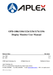
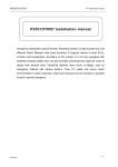
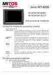
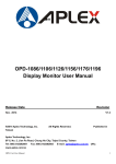
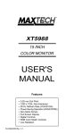
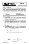
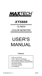
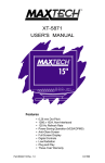
Industrial Touch Panel MT Installation manual MT080/084/104/121 Installation manual MT series Touch Panel, such as MT080-VNT/ MT084-TNT/ MT104-VNT/ MT121TNT, are expert HMIs with high functions and reasonable price answer to the needs for most of the automation equipments and systems. High coordination screen with plentiful colors relieve high speed and high quality. The industrial standard design let MT products meets harsh environment and work for long and steady. Apart from the basic functions other HMIs may have, it supports most PLC, inverter and temperature controller drivers on the market. Maxtech is laboring on the providing LAN function for standard models. The ultimate patent design front panel inspired customers to make their own HMI membrane styles. In addition to completely communication interfaces, flexible hardware design enables Ethernet TCP/IP operation. The modernistic outward, high brightness LCD with considerable memory let MT wins good reputations from users applying HMI in factory automation,wise buildings and special tool machines. MT Series Revision 1.1 0515 A-1 MT080/084/121 Specifications Items MT080-VNT MT084-TNT Number of Pixels 8.0" (diagonal) 8.4" (diagonal) 10.4" (diagonal) 12.1" (diagonal) 640X480 800X600 640X480 800X600 Contrast adjustable from touch screen Display Adjustment Back Light Touch Screen CCFL; Life time is 30,000 hours CCFL; Life time is 50,000 hours under 25°C and 85%RH humidity under 25°C and 85%RH humidity Analog resistive type; Max. Number of switches are 40x30 Chemically strengthened glass backing panel; Over 1 million point activations; Hard coat is resistant to most solvents and chemicals Input Power 24VDC±10%; Isolation; Under 30W RISC ARM9 32 Bit CPU CPU 16M Bytes(up to 64M Bytes) Flash Memory 64M Bytes System working Memory 128K(Up to 1024K Bytes) Battery Backed Memory COM1/9pin: RS232/RS422/RS485 COM2/9pin: RS232 . COM2/Terminal 4Pin : RS422/RS485 COM3 RS232 Communication Ports Host VER:1.1 X2 USB Optional with extension card ProfiBus Port IP65 / NEMA 4 Front Panel Seal Operating Temperature 0~50°C Storage Temperature -20~60°C 20-90% RH (non-condensing) Ambient Humidity Shock Endurance 0.5mm displacement, 10-55Hz, 2hours per X, Y, and Z-axis directions 10G, 11ms three times in each direction of X, Y, and Z axes FCC Part15 Class A RFI testing EN 55022/1998+A1:2000 Radiated Disturbance Test Electrostatic Discharge Test EN61000-4-2/1995+A1:1998 RF Electromagnetic Field Test EN61000-4-3/1996+A1:1998 EN61000-4-5/1995 Surge Immunity Test EMC Test Report Net Weight . Yes Ethernet Port Vibration Endurance MT121-TNT Color mode TFT LCD, 65536 colors Display Type Display Size MT104-VNT EN55022/EN55024/EN61000-3-2,3/EN61000-4-2,3,4,5,6,8,115 0.9Kg 0.9Kg 1.4Kg 2.2Kg Natural cooling Cooling A-2 MT Series Revision 1.1 0515 Industrial Touch Panel MT Installation manual Outlet and Cut out dimensions The outlet and cut out dimensions of MT080-VNT/MT084-TNT are shown as following. The outlet and cut out dimensions of MT104-VNT are shown as following. MT Series Revision 1.1 0515 A-3 The outlet and cut out dimensions of MT121-TNT are shown as following. A-4 MT Series Revision 1.1 0515 Industrial Touch Panel MT Installation manual Installation Before setup HMI, please cut a hole according to the cutout dimension. See below pictures for your installation reference. MT080-VNT 221.5mmx164.0mm MT084-TNT 221.5mmx164.0mm MT104-VNT 285.5mmx210.5mm MT121-TNT 301.5mmx228.0mm MT Series Revision 1.1 0515 A-5 How to install the HMI? Put the HMI to the cut hole and sew the lock screws at the four assembling holes on the HMI with average strength form the rear side. Please do not sew too tight and without equational strength or it will damage the touch panel. The operation of the Touch Panel A-6 MT Series Revision 1.1 0515 Industrial Touch Panel MT Installation manual MT080/104 is a kind of touch panel equipped with a VGA, 640(H) x 480(V) size LCD display and an analog input touch panel. The screen is a 40 x 30 chemically strengthened glass switches backing panel. The shapes of touch keys should be rectangles with sizes from minimum 8(H) x 8(V) pixels to maximum 640(H) x 480(V) pixels. MT084/121 is a kind of touch panel equipped with a super VGA, 800(H) x 600(V) size LCD display and an analog input touch panel. The screen is a 40 x 30 chemically strengthened glass switches backing panel. The shapes of touch keys should be rectangles with sizes from minimum 8(H) x 8(V) pixels to maximum 800(H) x 600(V) pixels. MT Series Revision 1.1 0515 A-7 FEATURES 1. Portrait 90° display & normal horizontal display supported 2. 100% quality test and industrial standard coating cases. 3. Adopts 32 bits high function; high reliability and fan-less ARM CPU 4. Equipped with genuine 65535 true colors, high brightness TFT modules 5. Provides 3 RS232/422/485 communication ports available in standard models 6. The standard 128KB backup memory, which can expend up to 1MB, allows storing Alarm, Recipe and historical data 7. Supports multi-languages, Windows build-in Fonts, BMP and JPG graphics and GIF animations 8. Provides transparent communication for designers to save their program adjustment time 9. The ultimate patent front panel design inspired customers to make their own HMI membrane styles. 10. The expansion bus expends various customize devices, such as motion control, temperature control, communication module and I/O module…etc. 11. High speed Ethernet port supports upload and download remote communication. 12. Provides accommodative Software, “PanelMaster”. A-8 MT Series Revision 1.1 0515 Industrial Touch Panel MT Installation manual ADVANTAGE FUNCTIONS MT080/084/104/121 are all compact HMIs with BIOS password protected function. This special function can be used to prevent the inside application data from being stolen or destroyed. The BIOS password is not set as a default situation. With BIOS upgrade function, wherever in the world, whenever the HMI needs to be updated new functions, this function supports upgrading without sending back to the factory. With serial number in the BIOS as an ID number of the HMI Supports checking the serial number from the HMI to assure a complete after service. The unique 2 BIOS systems patent design. In our past experiences, the HMI will not be able to run normally or even not be turned on the system due to the unstable electricity during operating. With the two BIOS system, customers need not send the damaged HMI back to the factory. Customize logos and User ID codes are available. Even for the small amount industrial products, this function let the customers have their own operating panel to complete an integer design. Automatically data download and communication ports COM1; COM2 detection. No need to setup. With BIOS recovery system while missing password can prevent system blocking due to missing password. MT Series Revision 1.1 0515 A-9 DIP Switches setting MT080/MT084/MT104/MT121 DIP Switches setting System Menu SW1 Not display system menu, go to ON-LINE communication after turns on. Display system menu when turns on. Not go to ON-LINE communication. ON OFF Emergency recovery the HMI BIOS to default value. Set to default OS version or customized OS version. Set to default BIOS version B. SW2 ON OFF SW3 SW4 OFF OFF ON OFF OFF ON ON ON HMI operation mode (Supports special functions for customized BIOS version) Reserved T o execute HMI Communication testing program (SW1,2 must set to Off) T o execute Key adjustment program or T ouch adjustment program (SW1,2 must set to Off) T o execute HMI application program SW5 ON OFF Reserved Reserved Reserved SW6 ON OFF Extension Module & Com3 port Selection Com3 Port enable Extension Module Enable ***The MT080/084/104/121 has a BIOS password recovery system to prevent damage when missing password. When you forget the password, which has been set to the HMI, this HMI can execute RUN AP/Calibrate operation but cannot execute BIOS/Download AP/Clear SRAM operations. When the users want to download new AP without password, please set all DIP switches to off (SW16=Off), When turns on HMI again, the HMI will display the clean all AP and old password screen. After proceeding this procedure, the HMI can be operated normally again. A-10 MT Series Revision 1.1 0515 Industrial Touch Panel MT Installation manual Startup Test When turns on HMI, it will display self-testing screen. After completed, HMI will show the system menu. FigureA-1 The HMI startup self-testing _normal **When turns on HMI, system will automatically execute hardware testing first to make sure hardware are normal or not. The result will show on the screen (Figure A-1). If there are problems, the HMI will not communicate with P.L.C. normally. When losing electricity during downloading or the PC breaks off downloading, after restarting the HMI, it will show Firmware Memory Checksum and Application Memory Checksum error. It means there is an abnormal downloading. To get a correct self-testing result, please execute a correct download AP procedure again. If losing electricity during downloading or the PC breaks off downloading when upgrading OS, it will surely cause download failure. If you restart the HMI, it will not display normal screens or even cannot be turned on. In that case, please set the DIP SW2 to OFF, restart the HMI to get a default BIOS version B then execute the upgrading OS program to get a correct OS version. Set the DIP SW2 to ON then the HMI can be turned on normally. MT Series Revision 1.1 0515 A-11 Startup Menu If the DIP SW1 set to off, after self-testing the MT080/084/104/121 will show startup menu as following figures. Situation 1: When SW2=OFF, it will show the default startup BIOS. FigureA-2 Startup BIOS_Default Situation 2: When SW2=ON, it will show the Panel Setup screen. FigureA-3 Panel Setup_ Remove the USB Sticker (Horizontal & Vertical) A-12 MT Series Revision 1.1 0515 Industrial Touch Panel MT Installation manual Situation 3 : When SW2=ON and there is an USB sticker insert to rear USB port, it will show the Panel Setup screen. FigureA-4 Panel Setup_ Insert the USB Sticker (Horizontal & Vertical) System menu Descriptions Password Download OS To receive new AP OS Ver. from COM Port. Yes*1 Copy to HMI To Copy AP to another HMI from COM1/2. Yes*1 Run AP Press “Run AP” or “ENT” to communicate with P.L.C.. Setting HMI keys and hardware functions testing. None LCD Test Check HMI LCD Display None Clock Setting HMI Time & Date Setting None Ethernet Setting Ethernet IP Address Setting None None*2 Memory Checking Check HMI memory size None Exit None Press “ESC” to return HMI hardware self testing *1.If sets a BIOS protection password to HMI, then the HMI will request the users to enter BIOS password. *2. If sets a login user password in AP, when selects Run AP, it will request the user to enter BIOS password. MT Series Revision 1.1 0515 A-13 Download AP To download AP to HMI, please make sure the download cable is connected properly. During the operating or in startup menu the HMI is ready to receive AP data sent by PC automatically. When download AP the SW2=ON. FigureA-5 The HMI downloading data from PC screens 1. Connect the PC COM1 or Com2 and HMI with a PC download cable. HMI Connector PC RS232C 9-pin Female --------- 9-pin Female HMI COM2 ---- PC COM HMI Connector PC Connector 9-pin Male ---------- 9-pin Female HMI COM1 ------ PC COM Serious Caution: Be sure turn off the power before connecting or it will damage the HMI communication components. 2. The HMI will judge the data correctness during downloading AP. When the PC sends AP data to HMI, the HMI will show download AP screen and display related information automatically to receive data. The HMI will show ”Incorrect Model !” when the Model No. is not set correctly in the AP data. Please select a correct Model No. from the software then download it again. If the HMI shows ”Incorrect User ID Code !”, then the hardware and software might not fit each other. Please check the brand name of the HMI to make sure you purchased a right hardware. A-14 MT Series Revision 1.1 0515 Industrial Touch Panel MT Installation manual COM Ports Define The communication port COM1 of MT080/084/104/121 can use as RS232C、 RS422 and RS485. The COM2 of MT080/084/104/121 can use as RS232, RS422 and RS485. Please make the right connecting cable according to the specifications. About the cable connecting figures of the HMI to other P.L.C., please refer to the P.L.C. manuals. Communication port COM1 in HMI is a DB-9P Female. COM1: pin definitions Pin 1 2 3 4 5 Function RS-422 TX+ and RS-485 + RS-232 RXD RS-232 TXD RS-422 RX+ Signal ground Pin 6 7 8 9 Function RS-422 TX- and RS-485 RS-232 RTS RS-232 CTS RS-422 RX- Communication port COM2 in HMI is a DB-9P Male. COM2: pin definitions Pin 1 2 3 4 5 Function RS-485 + RS-232 RXD RS-232 TXD Pin 6 7 8 9 Function RS-485 RS-232 RTS RS-232 CTS Optional 5V output Signal ground COM2: 4-pin definitions. RS422 and RS485。 Communication port COM3 in HMI is a Round-6P Female for RS232 use only. MT Series Revision 1.1 0515 A-15 LCD Adjustment and IP Address Setting To adjust the LCD brightness, (TFT model can not be adjusted the brightness), press [General] from MT Panel Setup screen or press [LCD Testing] from [Settings] in BIOS B. From [LCD Brightness], press [Increase Brightness] to increase the brightness, press [Decrease Brightness] to decrease brightness, press [Save Brightness] to save. Press [OK] to return to system screen. When you wish to use the Ethernet, please press [General] from MT Panel Setup screen and then you can set the IP Address. You can press the IP Address number and use [+] & [-] button to increase or decrease the IP Address number. Figure A-6 Panel Setup screen_ LCD brightness adjustment & IP Address Setting A-16 MT Series Revision 1.1 0515 Industrial Touch Panel MT Installation manual Power and Grounding Specifications Use DC24V as MT080/084/104/121 power input. The power consumptions are as following table. To ensure the MT080/084/104/121 hardware working properly, to avoid outside electromagnetism noise, please ground the power source properly. Items / Models MT080VNT MT084TNT MT104-VNT MT121-TNT 24VDC±10%; 20W Power consumption 0.8A Fuse Rating Power grounding caution: The products are all equipped with power terminals and lock assembling sets. The operating procedure is: 1.Screw off the power terminal. 2.Peel the 24V wiring(1.25mm) for 1 cm then plug in the power terminal. 3.Use line screw driver to screw the power terminal tight. Package content We are appreciated for your purchasing our products. Our standard package should be equipped with 5 items as following. Please check after receiving it. If there’s any shortage, please refer to the suppliers. MT080/MT084/MT104/MT121 unit x 1 (HMI Hardware) Power terminal x 1 (power terminal) Communication terminal x 1 (4-pin communication connector) MT080/ MT084: Installation screw nuts x 4 (Lock for assemble with screws) MT104/ MT121: Installation screw nuts x 8 (Lock for assemble with screws) MT080/ MT084/ MT104/ MT121 Installation Guide x 1 (Installation manual) Cautions If this product is used in a house, radio-wave interference might occur to other devices. In the case that it does occur, the user is requested to try a variety of remedies to solve the problem. MT Series Revision 1.1 0515 A-17 Power source MT080/084/104/121 is equipped with DC24V input power. If the supply power is other than DC24V, whatever less or excess, it will severely damage the HMI. Therefore, check the switching power supply supporting the DC power regularly. To avoid electronic shock, be sure the Power Cable is unplugged from the power outlet when connecting the cable to the HMI. Grounding From the FG terminal at the rear side of HMI, please make sure the grounding is made exclusively. When the FG terminal is connect, be sure the wire is grounded. Without grounding, the operation of HMI may be severely affected by excess external noise levels and vibrations. Use a cable at 2 m㎡ (AWG 14) to ground the equipment. Ground resistance must be less than 100Ω(class3).Note that the ground cable must not be connected to the same ground point as the power circuit. Installation Mount the HMI from the front of a suitable preserved hole. Attached the brackets behind. Fasten the screw of the brackets with proper force. Tightening too much may cause damage to the structure of the unit. Input and Output signal lines must be separated from the power cables for operational circuits. Use shielded cables or it may cause unpredictable problems. Do not allow cut wires, filling, or shavings to fall inside a unit or block when drilling holes or connecting cables/lines. Environment Do not install in areas subject to excessive dust, oily mist, conductive dust, corrosive gas, or flammable gas. Do not mount in areas subject to shock or vibration. Do not mount in areas subject to high temperature, moisture, or rain. Indicated loss of life, severe personal injury, or substantial property damage will result if proper precautions are not taken. A-18 MT Series Revision 1.1 0515 Industrial Touch Panel MT Installation manual Remark: Maxtech Human Machine Interface : MT-080-VNT and MT-508-TV NO Product Information 1 CPU 2 “ New ” MT-080-VNT 2007.1.10 MT-508-TV RISC 32 Bits CPU Intel PXA255 Display 8” TFT , 65535 colors 8" TFT , 256 colors 3 Brightness 350 cd/m ~450 cd/m 4 Backlight 5 Backlight life time 6 Resolution 7 8 9 2 2 400 cd/m 2 CCFL(U type)x1 CCFLx1 50000hrs (Under normal temperature) 40000hrs (Under normal temperature) 640X480 (8" diagonal) 640X480 (8" diagonal) Flash Memory 16 MB ~ 64MB (Optional) flash memory 2MB flash memory Battery Backup 128 KB ~ 1 MB (Optional) 128 KB 1 RS-232 (HMI-PC or HMI-PLC) 1 RS-232 (HMI-PC) 1 RS232/422/485 (HMI-PLC) 1 RS232/485 (HMI-PLC) 1 RS232/422/485 (HMI-PLC) 1 Printer Port (Optional : Profibus Module) none Communication Port 10 Extension Port 11 USB Port 2 USB Host Ver.2.0 Full Speed Ports none 12 Ethernet 10/100 Ethernet Port (Optional) 13 Dimension HxWxD:176x233x50mm HxWxD:231x176x55mm 14 Graphics BMP / JPG / GIF BMP 15 Weight Approx: 0.9 kg Approx:1.2 kg 16 EMI Complies with FCC class A Complies with FCC class A 17 CE Approved Yes Yes 18 Operating temperature 0° ~ 50°C (32° ~ 120°F) 0° ~ 45°C (32° ~ 113°F) 19 Front Panel Meets NEMA4 / IP65 NEMA4 / IP65 20 Relative humidity 10% ~ 90% RH @ 50°C, non-condensing 10% ~ 90% RH @ 40°C, non-condensing 21 Software Panel Master Easy Builder Remark: Maxtech Human Machine Interface : MT-104-VNT and MT-510-T MT Series Revision 1.1 0515 2007.1.10 A-19 NO Product Information 1 CPU 2 Display 3 Brightness 4 Backlight 5 Backlight life time 6 Resolution 7 “ New “ MT-104-VNT MT-510-T RISC 32 Bits CPU RISC 32 Bits CPU 10.4” TFT , 65535 colors 10.4" TFT , 256 colors 2 350 cd/m ~450 cd/m 2 400 cd/m 2 CCFLx2 CCFLx2 50000hrs (Under normal temperature) 50000hrs (Under normal temperature) 640X480 (10.4" diagonal) 640X480 (10.4" diagonal) Flash Memory 16 MB ~ 64MB (Optional) flash memory 2MB flash memory 8 Battery Backup 128 KB ~ 1 MB (Optional) 128 KB 9 Communication Port 1 RS-232 (HMI-PC or HMI-PLC) 1 RS232/422/485 (HMI-PLC) 1 RS232/422/485 (HMI-PLC) 1 RS-232 (HMI-PC) 1 RS232/485 (HMI-PLC) (Optional : Profibus Module) none USB Port 2 USB Host Ver.2.0 Full Speed Ports none 12 Ethernet 10/100 Ethernet Port (Optional) 13 Dimension HxWxD:224x297x52mm HxWxD:315x238x62mm 14 Graphics BMP / JPG / GIF BMP 15 Weight Approx:1.4 kg Approx: 2.0 kg 16 EMI Complies with FCC class A Complies with FCC class A 17 CE Approved Yes Yes 18 Operating temperature 0° ~ 50°C (32° ~ 120°F) 0° ~ 45°C (32° ~ 113°F) 19 Front Panel Meets NEMA4 / IP65 NEMA4 / IP65 20 Relative humidity 21 Software 10 Extension Port 11 10% ~ 90% RH @ 50°C, noncondensing Panel Master A-20 10% ~ 90% RH @ 40°C, non-condensing Easy Builder MT Series Revision 1.1 0515