1
PDS200 Power over Ethernet Device
Server User Manual
■ ABOUT
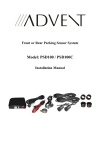
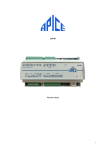
PDS200 is an external usage Power over Ethernet Device Server (Serial-toEthernet converter). It includes the function of GIGA-TMS’s products- DS203 (Device
Server) and PS200 (Power over Ethernet Splitter). It can connect existing serial
device (RS232 or RS485) to Ethernet network and supplies DC12V or DC5V output
for the serial device (RS232 or RS485). It has RS232 and RS485 serial ports. You
can set the output signal to RS232 or RS485 by adjusting the DIP Switch that located
at the bottom case of PDS200.
The product offers a compact disk which includes Tibbo Device Server Toolkit
software and Virtual Serial Port driver for Windows and Linux. To manipulate
Ethernet and serial’s settings, please refer to Tibbo Device Server Toolkit
Documentation.
■ APPLICATION
For those areas that AC power is not available, PDS200 provides the easiest
way to power Ethernet device (supply DC12V or DC5V power). The hardware of
PDS200 includes an Auto-MDIX* 10/100BaseT Ethernet port, a RS232 serial port, a
RS485 serial port and an internal processor that "glues" network and serial sides
together.
From the hardware standpoint, PDS200 can be regarded as a universal
platform that is suitable to run a variety of network and serial communication
applications.
Most functions of PSD200 are provided by Application Firmware. PDS200
runs in Application Firmware ("Serial-to-Ethernet" mode) that turns the PDS200 into a
ready-to-work serial-to-Ethernet converter that can connect almost any kind of serial
device to Ethernet (TCP/IP) network.
Application Firmware has fixed function. If you want to adjust the behavior of
PDS200, you can specify the values of programmable parameters (settings) defined
in this firmware. In addition, Application Firmware of PDS200 can be upgraded and
firmware upgrade is via serial port or Ethernet port. Serial upgrade is facilitated by a
so-called Monitor- a fixed "service" firmware inside the PDS200. Network upgrade
relies on the Application Firmware itself - there is a self upgrade algorithm with Tibbo
Device Server Toolkit software.
* Auto-MDIX means automatic detection of "straight" and "cross" cables.
■ FUNCTIONALITY
DC12V or DC5V output for RS232 or RS485 device
Full- and half-duplex serial port modes.
Server, Client, and Server/Client network ("routing") modes.
Numerous options for connection, serial port, etc.
8KB data buffers (one in each direction).
Configuration stored in EEPROM.
Setup through the serial port or network (UDP, Telnet).
Remote control of RTS, CTS, DTR, and DSR lines.
"On-the-fly" commands for immediate serial port configuration.
TM951218
Serial-side "modem" commands for network connection control.
Direct control of ADSL modem.
Support UDP, TCP, ARP, ICMP (ping), DHCP, PPPoE, LCP.
■ SPECIFICATIONS
IEEE 802.3af Power over Ethernet Device Server
(Serial-to-Ethernet Converter)
PDS200
Compliant to all IEEE 802.3af specifications.
Present class 0 PD to PSE.
Extract power from data pair (1,2,3,6), spare pair
(4,5,7,8) or both pairs. PoE signature on any one
pair.
RJ-45 (PoE in), 10/100BaseT, auto-MDIX Ethernet
port
RS232 mode: RX, TX, RTS, CTS, DTR, DSR lines
Default settings: 19200-N-8-1 (DIP Switch all OFF)
RS485 mode: RX+/-, TX+/-, automatic direction
control;
Default settings: 19200-N-8-1 (DIP Switch all ON)
12VDC, 660mA (Max.);
5VDC, 240mA (Max.), *internal circuit used partial power
Product
Model
IEEE802.3af Compliant
2 Pair/4 Pair Power Extraction
Ethernet Connector
RS232 Connector
RS485 Connector
DC 12V Output (DC Jack)
DC 5V Output (4P connector)
Number of Device Can be
Powered
Ethernet Cable
1
TIA/EIA-568, Category 5/5e cable
LED Indicator
Yellow - PoE working normally and 12VDC ready.
Red - DS operation under the error mode.
Green - Network working normally.
Dimensions
100(L) * 98 (W) * 21(H) mm
Weight
150g
Operating Environment
0~50 Degree C, 5%~90% RH
Storage Environment
-10~70 Degree C, 5%~90% RH
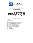
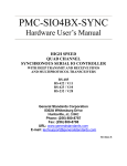
■ Ethernet Port Pin Assignment & RS232/485 Port Pin Assignment
PoE IN
8
#1
#2
#3
#4
#5
#6
#7
#8
RS232/485 Port
1
TX+
TXRX+
SP+
RXSP-
#1
#2
#3
#4
#5
#6
#7
#8
#9
No
connection
RS-RX
RS-TX
RS-DTR
GND
RS-DSR
RS-RTS
RS-CTS
No
connection
#1
+5V
#2
#3
#4
R+/T+
R-/TGND
※ The mark "DC12V Out" on the right figure is output Power Jack.
TM951218
■ Ethernet Port Pin Assignment
Ethernet port of PDS200 is 10/100BaseT type.
Connector is RJ45 type. The following is pin assignment:
#1
#2
#3
#4
#5
#6
#7
#8
TX+
TXRX+
SP+
RXSP-
■ RS232 Port Pin Assignment
DB9M RS232 connector has the following pin assignment:
#1
#2
#3
#4
#5
#6
#7
#8
#9
<No connection>
RX (input)
TX (output)
DTR (output)
Ground
DSR (input)
RTS (output)
CTS (input)
<No connection>
TM951218
■ RS485 Port Pin Assignment
RS485 connector has the following pin assignment:
T+ pin (#2) is RS485 positive differential-signal (T+/R+), T- pin (#3) is RS485
negative differential-signal (T-/R-).
■ DC 5V Output (4P Connector)
The RS485 connector also supplies DC 5V power output:
Output (5V) pin (#1) correspond to ground (GND) pin (#4) is DC5V output port, this
power can supply for RS232 or RS485 device which uses DC5V power source. The
DC5V tolerance range is 4.75VDC ~ 5.25VDC, and maximum output current is
240mA.
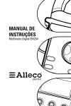
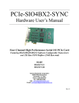
GIGA-TMS supplies a power cable WAS-T0471. This cable originally is used for
DC12V output. If RS232 or RS485 device does not use DC12V power source, you
can use WAS-T0471 as DC5V output cable by cutting the B end of WAS-T0471 and
then peeling the black cover of WAS-WT0471 around 2.0 cm and peeling the covers
of inner red and white wires around 0.5 cm as the pictures below. Then connect the
red wire to output (5V) pin (#1) and connect the white wire to the ground (GND) pin
(#4). DC5V will be output from the A end of WAS-T0471 for Serial Device usage.
WAS-T0471
Red wire
White wire
WAS-T0471 with black cover
1.5 cm
0.5 cm
TM951218
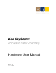
■ DC 12V Output (DC Jack)
The DC jack of PDS200 accepts "small" power connector with 3.5mm diameter. It
outputs DC12V power for RS232 or RS485 device. Please use WAS-T0471 power
cable that supplied by GIGA-TMS. Output power tolerance range is 11.4VDC ~
12.6VDC and maximum output current is 660mA. On the DC jack, the ground is
"the outside" circle, shown on the figure as below.
■ DIP Switch setting for RS485 communication
The DIP Switch is located at the bottom case of PDS200. All DIP Switch set to ON
position indicates that data is routed through PDS200 via RS485 port.
■ DIP Switch setting for RS232 communication
The DIP Switch is located at the bottom case of PDS200. All DIP Switch set to OFF
position indicates that data is routed through PDS200 via RS232 port.
TM951218
■ Status LEDs
PDS200 (PoE Device Server) features one Power Status LED (yellow LED)
and two Status LEDs (red LED and green LED). Yellow LED means that PoE
function works normally and 12VDC is ready. Red LED and green LED display
various states of device operation. The states of PDS200 are indicated by way of
playing "LED patterns". Patterns are represented by graphics in the following
manner:
The pattern
means that both red LED and green LED blink three times
means that red LED makes one
together. The pattern
long blink and then two short ones.
TM951218
Status LEDs (red LED and green LED) display various status information
depending on what firmware is running at the moment. Follow the descriptions
below to learn more about the behavior of these LEDs under different conditions:
Status LED behavior in Application Firmware
Powerup pattern. This pattern is played once
when the PDS200 is switched on.
Buzz pattern. Both LEDs blink fast- this pattern
is played when the PDS200 receives the Buzz
(B) command. This is used to identify a
particular PDS200.
Status LEDs of the PDS200 are playing a serial
programming mode pattern when the serial port
of the PDS200 is in the serial programming
mode.
Status LEDs of the PDS200 are playing an
error mode pattern when the PDS200 is in the
error mode (unless the serial port of the
PDS200 is in the serial programming mode).
Ethernet Port failure. Indicates that the
Ethernet port hardware is malfunctioning and
network communications with the PDS200 is not
possible.
IP-address not obtained. Occurs at startup
when DHCP (DH) setting is 1 (enabled) and
the PDS200 has not yet obtained its IP-address
from the DHCP server.
PPPoE login failed. Occurs at startup and
means that either PPPoE login name and
password (defined by PPPoE Login Name
(PL) and PPPoE Login Password (PD)
settings) are incorrect or PAP authentication
protocol used by the PDS200 is not supported
by Access Concentrator.
Data connection is closed. This pattern
means that no data connection (TCP or UDP)
with any network host is currently established
so the PDS200 is idle.
Sending ARP. Displayed when the PDS200 is
sending ARP requests to find out MAC-address
of the destination network host with which the
PDS200 is about to establish a connection.
TCP connection is being opened. Indicates
that TCP connection (either incoming or
outgoing) is being established (i.e. SYN-SYNACK exchange is in progress).
TCP connection reset (rejected) by the
network host. Means that the TCP connection
has been reset (using RST packet) by the
network host to which the PDS200 has tried to
connect.
Link Server login in progress. Means that the
PDS200 has already established TCP
connection to the Link Server and is now
attempting to login.
Link Server login failed. Means that data
connection to the Link Server could be
TM951218
established but the server has rejected this
PDS200 (because the data in the Owner Name
(ON), Device Name (DN), or Password (PW)
setting is incorrect or for some other reason).
Data connection is established or being
closed. Means that data UDP "connection"or
TCP connection is currently established or
that TCP connection is being closed (i.e. FINACK-FIN-ACK exchange is in progress).
Data is being routed, no overruns detected.
This pattern is played when the data
connection is established and the data is being
routed through the PDS200.
Buffer overrun, no data routing. This pattern
is displayed when the data connection is
established and the routing buffer overrun has
been detected (within the present data
connection).
Buffer overrun + data routing. Data routing
and overrun can be displayed at the same time.
Status LED behavior in Monitor Firmware
Fast-blinking pattern means that neither
application firmware, nor the NetLoader can
be found in the FLASH memory of the PDS200.
The way out of this situation is to upload
application firmware and the NetLoader into the
device via its serial port.
Slow-blinking Green Status LED means that
the serial upgrade was completed successfully.
Slow-blinking Red Status LED means that
there was a timeout while waiting for the
XMODEM data. If this happens right in the
beginning of the serial upgrade then most
probably this is caused by incorrect serial
settings on the PC side, incorrect serial cable
wiring, or incorrect XMODEM start procedureXMODEM must be started on the PC first, and
only then the DS is switched on (with he Setup
button pressed; Note: Setup button is
nearby EM203 module in the case).
Communications error. This pattern means
that an error was detected on the protocol level
in XMODEM communications. Most often this
means that incorrect communications
parameters are set on the PC side.
Firmware file is too big. This pattern means
that the file you are trying to upload into the
PDS200 is too big. Check if you have selected
a correct file.
FLASH failure. This pattern means that
internal FLASH memory of the PDS200 is
malfunctioning.
Note: Please refer to Device Server Toolkit (DST) software for Windows under item
Software Manuals in HTML Help file- sois_manual in CD for more detail description
about software- DS Manager, VSP Manager, and Connection Wizard.
TM951218