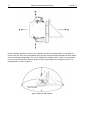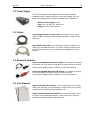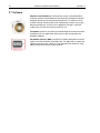
1
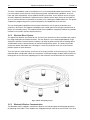
Keo SkyScan4
Articulated Mirror Assembly
Hardware User Manual
Version 1.0
June 12, 2012
© Copyright 2004 – 2012
Keo Scientific Ltd.
Suite 404, 1300 – 8th St SW
Calgary, Alberta, Canada
T2R 1B2
TEL: +1 (403) 452-7222
FAX: +1 (403) 206-7680
All rights reserved. No part of this publication may be reproduced by any means without the written
permission of Keo Scientific Ltd.
Printed in Canada.
Windows is a registered trademark of Microsoft Corporation.
SmartMotor and Combitronic are registered trademarks of Animatics Corporation.
Pelican is a registered trademark of Pelican Products, Inc.
PowerGrip and GT are registered trademarks of Gates Corporation.
The information in this publication is believed to be accurate as of the publication date. However,
Keo Scientific Ltd. does not assume any responsibility for any consequences including damages
resulting from the use thereof. The information contained herein is subject to change without notice.
Revision of this publication may be issued to incorporate such change.
Table of Contents
iii
Table of Contents
1
Introduction............................................................................................................... 7
2
System Components ................................................................................................ 9
2.1 System Components Overview ................................................................................... 9
2.2 SkyScan Unit ................................................................................................................. 9
2.2.1
2.2.2
2.2.3
2.2.4
2.3
2.4
2.5
2.6
2.7
Drive System ............................................................................................................................9
Electrical Brush System ........................................................................................................ 10
Bluetooth Wireless Communication ..................................................................................... 10
Coordinate System ............................................................................................................... 11
Power Supply .............................................................................................................. 13
Cables.......................................................................................................................... 13
Bluetooth Adaptors .................................................................................................... 13
User Manuals .............................................................................................................. 13
Software ...................................................................................................................... 14
3
Installation Overview ............................................................................................... 15
4
System Setup ......................................................................................................... 17
4.1
4.2
4.3
4.4
4.5
4.6
4.7
4.8
5
Introduction................................................................................................................. 17
System Requirements ................................................................................................ 17
Unpacking the System ............................................................................................... 18
Equipment and Parts Inventory ................................................................................. 19
Preparing the Mirrors and Window ........................................................................... 20
Mounting ..................................................................................................................... 20
Driver Installation........................................................................................................ 22
Software Installation .................................................................................................. 22
Operation ................................................................................................................ 23
5.1 The First Power-Up .................................................................................................... 23
5.2 Communicating with the SkyScan4........................................................................... 24
5.3 Firmware Updates ...................................................................................................... 24
6
Command Reference .............................................................................................. 25
6.1
6.2
6.3
6.4
6.5
6.6
6.7
Command Overview ................................................................................................... 25
Error Codes ................................................................................................................. 26
Help Menu Command................................................................................................. 26
Report a Configuration Parameter Command.......................................................... 26
Set a Configuration Parameter Command................................................................ 27
Start a Trajectory Command ..................................................................................... 27
Start a Homing Routine Command ........................................................................... 28
iv
SkyScan4 Hardware User Manual
6.8
6.9
6.10
6.11
6.12
6.13
6.14
6.15
6.16
6.17
6.18
6.19
7
Version 1.0
Report Axis Offsets Command................................................................................... 28
Report Current Axis Positions Command ................................................................. 28
Move to Position Command ....................................................................................... 29
Stop All Motion Command ......................................................................................... 30
Stop Position and Velocity Motion Command .......................................................... 30
Stop Trajectory Command ......................................................................................... 30
Report Operating Status Command .......................................................................... 31
Initialize Trajectory Command ................................................................................... 32
Define a New Trajectory Command ........................................................................... 32
Report Current Velocity Command ............................................................................ 33
Move at Velocity Command........................................................................................ 33
Exit Custom Command Mode Command .................................................................. 34
Configuration Parameters........................................................................................ 35
7.1 Parameter 0: Azimuth Home Offset ........................................................................... 35
7.2 Parameter 1: Zenith Home Offset .............................................................................. 35
7.3 Parameter 2: Cam Interpolation Mode ...................................................................... 36
8
Warranty & Service .................................................................................................. 37
8.1 Limited Warranty ......................................................................................................... 37
8.2 Contact Information .................................................................................................... 37
Appendix A
Specifications ........................................................................................ 39
Basic.....................................................................................................................................39
Performance ........................................................................................................................39
Window ................................................................................................................................39
Mirrors ..................................................................................................................................40
Appendix B
Outline Drawings ................................................................................... 41
Mounting Flange Layout ..................................................................................................... 41
Side Profile ...........................................................................................................................42
Top Profile............................................................................................................................43
Appendix C
Bluetooth Adaptor Configuration ........................................................... 45
Appendix D
Firmware Update Procedure ................................................................. 49
Table of Figures
v
Table of Figures
Figure 1: Typical System Components .........................................................................................................9
Figure 2: Brush and Slip Ring Layout......................................................................................................... 10
Figure 3: SkyScan Coordinate System ...................................................................................................... 11
Figure 4: Top-Down Coordinate System View ........................................................................................... 12
Figure 5: SkyScan in Parked Position ........................................................................................................ 12
Figure 6: SkyScan4 Shipping Locks .......................................................................................................... 19
Figure 7: Azimuth Window Plate ................................................................................................................ 20
Figure 8: Zenith Window Plate ................................................................................................................... 20
Figure 9: Correct DIP Switch Positions ...................................................................................................... 45
Figure 10: SD1000U Device Information Settings Page ............................................................................ 45
Figure 11: SD200 Device Information Settings Page ................................................................................. 46
Figure 12: SD200 Waiting for Connection .................................................................................................. 46
Figure 13: SD1000U Connection(out) Settings Page ................................................................................. 47
Figure 14: ParaniWIN Connection Successful Dialog ................................................................................ 47
Figure 15: SD1000U Device Setting Page ................................................................................................. 48
Figure 16: ParaniWIN Configuration Complete Dialog ............................................................................... 48
Figure 17: SMI Port Properties ................................................................................................................... 49
Figure 18: SMI View Layout........................................................................................................................ 50
Figure 19: SMI Hex String Entry ................................................................................................................. 51
Figure 20: SMI Response to X! ................................................................................................................... 51
Figure 21: SMI Browse for SMX File .......................................................................................................... 51
Figure 22: SMI Select Motor Dialog ........................................................................................................... 52
Figure 23: SMI Upload Progress ................................................................................................................ 52
Figure 24: SMI Upload Finished ................................................................................................................. 52
vi
SkyScan4 Hardware User Manual
This page is intentionally blank.
Version 1.0
Section 1
Introduction
7
1 Introduction
Thank you for purchasing a Keo SkyScan4 system from Keo Scientific. This latest version of our
SkyScan system is the culmination of several years of design iterations and is our most capable system
yet.
The Keo SkyScan4 is a dual first-surface mirror assembly that can be pointed towards any point in the
sky by rotating the two mutually perpendicular axes, one of which is vertical and the other horizontal, to
the desired positions. Rotation about the vertical axis varies the azimuth (compass bearing) of the
pointing direction while rotation about the horizontal axis varies the zenith angle of the pointing direction.
Both axes are capable of full 360 degree continuous rotation through the use of electrical brushes and
slip rings for power transfer and Bluetooth for communication. This improvement over our legacy
systems, which were limited to approximately 200 degrees of azimuth travel and required complicated
calculations for achieving full 360 degree pointing, allows for simplified control of the device and smooth
tracking of trajectories.
The SkyScan system is suitable for use with space weather, aeronomical, and surveillance
instrumentation such as photometers, narrow-field imagers and Fabry-Pérot Interferometers (FPIs). It
can also be used as a heliostat or trajectory tracker.
High-reflectance, first-surface quality mirrors and a high-transmittance entrance window are used to
minimize light loss through the system. Modern servo-motor technology is used drive the axes to
provide fast, repeatable, and high-precision pointing or scanning.
All that is needed to communicate with and control the SkyScan system is a suitable computer with an
available USB2 port.
8
SkyScan4 Hardware User Manual
This page is intentionally blank.
Version 1.0
Section 2
System Components
9
2 System Components
2.1 System Components Overview
A standard SkyScan4 system consists of the SkyScan unit, a power supply with AC cord, a tether cable,
two Bluetooth adaptors (one with USB power cable), a NULL modem serial cable, user manuals, and
software CDs.
Figure 1: Typical System Components
2.2 SkyScan Unit
This is the main component of the SkyScan system. It is a selfcontained unit comprising two mutually perpendicular axes (azimuth
and zenith) each of which has an Animatics SmartMotor™ for precise
motion control.
2.2.1
Drive System
This new and improved SkyScan4 uses PowerGrip® GT®2 synchronous belts
for transmitting power from the gearboxes to the axes. The unique curvilinear
tooth profile delivers smooth, quiet operation and precise registration with
virtually no backlash. These belts are combined with precision gearboxes and
Animatics Class 5 SmartMotor integrated servo motors to provide a high
accuracy, long lasting, and zero maintenance drive system.
10
SkyScan4 Hardware User Manual
Version 1.0
The Class 5 SmartMotors used on the SkyScan are a new and improved product from Animatics. These
new servo motors now feature a 5x faster processing speed, expanded math capabilities, on-the-fly
linear and spline interpolation, and an optional CAN bus connection. On the SkyScan we are using the
Animatics proprietary Combitronic™ protocol over the CAN bus which allows for one of the motors to
act as a master and execute commands on the other, all at a blazing fast 1MBaud data rate. This greatly
simplifies the programming of the system and improves the coordination of the two axes.
The new floating point capabilities of these motors allow for the user to specify all positions and
velocities in their native units (degrees and degrees per second) rather than having to calculate them in
device units (encoder counts). The modulo encoder count capabilities completely eradicate any position
overflow issues found in previous SkyScan devices.
2.2.2
Electrical Brush System
The original Keo SkyScan was limited to 200° of travel in the azimuth axis due to limitations put in place
by having wired power and communications. The new SkyScan uses a two pronged approach to get
around this limitation: electrical brushes and brass slip rings for power transfer into the rotating device
and Bluetooth wireless communications for communicating with the device. This allows for full 360°
continuous rotation about both axes. No longer is it necessary to flip the zenith axis to the inverted
position to point in some directions.
There are two sets of four brushes: four on the inner slip ring and four on the outer slip ring. This quadredundant brush configuration allows for a continuous uninterrupted supply of power while the device is
rotating while at the same time supporting the full 10A maximum current draw from the servo motors.
Figure 2: Brush and Slip Ring Layout
2.2.3
Bluetooth Wireless Communication
The Bluetooth wireless adaptors used with the SkyScan are industrial grade and designed specifically
for replacing serial cables. These adaptors are shipped paired with each other so that all the user has to
Section 2
System Components
11
do is install a driver and plug the USB adaptor into the host computer. The SkyScan will appear as a
regular serial (COM) port on the host computer that can be opened and used as you would any other
serial port. This allows for maximum compatibility with a wide range of host environments.
2.2.4
Coordinate System
Important Information
All references to cardinal directions (north, south, east, and west) in this
manual are with respect to the earth’s geographic coordinate system, not
the magnetic coordinate system. Aligning the device with magnetic north
may cause significant errors in the pointing accuracy of the system.
The SkyScan system uses a spherical coordinate system defined by an azimuth angle and a zenith angle
where the azimuth angle is measured clockwise from north and the zenith angle is measured from the
zenith in the direction of the azimuth angle (see Figure 3). Since all possible points can be described with
a 0 to 360° azimuth range and a 0 to 180° zenith range, negative zenith values are not strictly necessary.
The SkyScan will however accept negative zenith angles which are simply interpreted as a positive
zenith angle in the azimuth angle + 180° azimuth direction.
Note
The SkyScan mounting plate is designed so that the power connector is oriented in
the south direction.
Figure 3: SkyScan Coordinate System
The coordinates of the SkyScan are always given by the position of the two axes, i.e. the azimuth and
zenith angles of the point the SkyScan is pointing at. In this manual they are represented as a position
pair, (Az,Ze). For example, an azimuth angle of 110° and a zenith angle of 45° would be represented as
(110°,45°).
Due to the optical geometry of the SkyScan unit, the azimuth head will always appear to be lagging the
actual azimuth position by 90 degrees. As shown by the top-down view of Figure 4, despite the physical
azimuth axis being aligned with north, the actual azimuth angle is 90 degrees. In this same figure, the
zenith axis is also positioned at 90 degrees making the current position of the SkyScan (90°,90°).
12
SkyScan4 Hardware User Manual
Version 1.0
Figure 4: Top-Down Coordinate System View
After the SkyScan performs a homing cycle it positions itself in the parked position. This position was
chosen to be (90°,180°) which corresponds to the physical azimuth axis being aligned with north and the
zenith axis pointing straight down. This serves to protect the window, mirrors, and any instrumentation
you may have attached to the SkyScan by preventing any direct light from entering the system. The
parked position is shown in Figure 5.
Figure 5: SkyScan in Parked Position
Section 2
System Components
13
2.3 Power Supply
The AC line-voltage line cord supplied with your system should be
compatible with the region to which the system was shipped. If the line
cord is incompatible, please contact Keo Scientific for a replacement.
Maximum Power Output: 240 W
Input: 100 – 240 VAC, 50 – 60 Hz, 6.3A
Output: 24 VDC @ 10A maximum
2.4 Cables
Power Supply to SkyScan Tether Cable: The standard 7m (23’) tether
cable has LEMO connectors that interconnect the power supply with the
SkyScan4.
NULL Modem Serial Cable: The standard 3m (10’) NULL modem serial
cable has female DB9 connectors. This cable is used to interconnect the
host PC with one of the axes of the SkyScan4 for upgrading the device
firmware.
2.5 Bluetooth Adaptors
Sena Parani SD200 Bluetooth Serial Adaptor: This adaptor is installed on
the azimuth axis of the SkyScan4 and forms the device end of the wireless
communication bridge between the device and the host computer.
Sena Parani SD1000U Bluetooth USB Adaptor: This adaptor is installed
on the host computer and forms the host end of the wireless
communication bridge between the device and the host computer.
2.6 User Manuals
SkyScan4 Hardware User Manual: This manual describes how to install
and use the SkyScan4 system components. A PDF version of this manual
is provided on the Documentation and Utilities CD.
SkyScan Control Software User Manual: This manual describes how to
install and use the application program. A PDF version of this manual is
provided on the Documentation and Utilities CD.
14
SkyScan4 Hardware User Manual
Version 1.0
2.7 Software
SkyScan Control Software: The SkyScan4 system can be operated by
using the SkyScan Control Software, Keo Scientific’s Windows® software
designed specifically for controlling the SkyScan4. This software can be
used to manually control the device or automatically control it using a predetermined trajectory. It also has the capability of running in ‘Heliostat’
mode which will make the SkyScan4 track the sun.
ParaniWIN: Located in the Utilities\ParaniWIN folder of the Documentation
and Utilities CD, this application allows for the initial configuring of the
Bluetooth adaptors.
SmartMotor Interface (SMI): Located in the Utilities\SmartMotor Interface
folder of the Documentation and Utilities CD, this application is required to
update the firmware of the SkyScan. See Appendix D for details on using
SMI to update the firmware of your SkyScan.
Section 3
Installation Overview
15
3 Installation Overview
The list below briefly describes the sequence of actions required to install and operate your system.
Refer to the indicated references for more detailed information.
Action
Reference
1. If the system components have not already been unpacked, unpack
them and inspect their carton(s) and the system components for intransit damage.
Section 4.3: Unpacking
the System, page 18
2. Verify that all system components have been received.
Section 4.4: Equipment
and Parts Inventory,
page 19
3. If the components show no signs of damage, verify that the appropriate
power cord has been supplied with the power supply.
Section 4.2.2: Power
Requirements, page 17
4. Remove the protective plastic from the mirrors and window.
Section 4.5:
Preparing the Mirrors
and Window, page 20
5. Securely mount the device in a suitable location.
Section 4.6: Mounting,
page 20
6. Attach the SD200 Bluetooth Serial adaptor to the azimuth axis.
Section 4.6: Mounting,
page 20
7. Remove the shipping locks.
Section 4.6: Mounting,
page 20
8. If the device drivers are not already installed in the host computer, install
them and connect the SD1000U Bluetooth USB adaptor.
Section 4.7: Driver
Installation, page 22
9. Turn the device ON.
10. Turn on the computer and begin running the application software.
SkyScan Control
Software Manual
16
SkyScan4 Hardware User Manual
This page is intentionally blank.
Version 1.0
Section 4
System Setup
17
4 System Setup
Caution
To minimize the risk to users or to the system equipment, turn the system
OFF before any cables are connected or disconnected.
4.1 Introduction
The Keo SkyScan4 system consists of three hardware components:
•
•
•
SkyScan unit
Power supply
Cables
All of the components and cables required to use the SkyScan are included with your shipment. Keep all
of the original packing materials so you can safely ship the SkyScan system to another location or return
it for service if necessary. If you have any difficulty with any step of the instructions, contact Keo
Scientific support. For support contact information, refer to Section 8.2.
Hardware installation will consist of:
•
•
Mounting the SkyScan in the desired location.
Connecting various cables and wireless devices.
Software installation depends on the application software you will be using to run the system. Refer to
the manual supplied with the software for information about installing and setting it up.
4.2 System Requirements
4.2.1
Environmental Requirements
Storage temperature: ≤80°C
Operating environmental temperature: +5°C to +70°C
Relative humidity: ≤30%; non-condensing
4.2.2
Power Requirements
The SkyScan unit receives its power from the supplied power supply which in turn plugs into an AC
power source.
Power supply input voltage range: 100 VAC to 240 VAC (50/60 Hz)
Power supply input current: 6.3A
18
4.2.3
SkyScan4 Hardware User Manual
Version 1.0
Mechanical Requirements
A sturdy platform capable of supporting 50lbs (18kg). The more rigid the platform the smoother the
operation of the SkyScan will be during quick acceleration and deceleration.
4.2.4
Host Computer
Note
Computers and operating systems all undergo frequent revision. The following
information is only intended to give minimum computer requirements. Please contact
Keo Scientific to determine your specific needs.
The SkyScan system needs a host computer to communicate with and control it. The SD1000U
Bluetooth USB adaptor provided with the system will work on virtually any operating system in both 32bit and 64-bit environments: Windows XP or newer, Linux, or Mac OS X. Drivers for these environments
can be found on the Documentation and Utilities CD in the Drivers\SD1000U Bluetooth USB Adaptor
folder.
The SkyScan Control Software provided with your SkyScan system is only compatible with Windows XP
or newer in both 32-bit and 64-bit environments. If you want to use the SkyScan with a non-Windows
platform you will need to write your own control software. The SkyScan has an easy to use interface that
is controlled with simple commands which are sent to its virtual serial port. See Section 5 for details on
communicating with the SkyScan system and see Section 6 for details on the available commands.
4.3 Unpacking the System
While unpacking the SkyScan, check the system components for possible signs of shipping damage. If
there are any, notify Keo Scientific immediately.
The system is shipped in a Pelican™ case for maximum protection. The case can also be used to store
the device while it is not in use. Please save the case so that it can be used to ship the device to a new
location or to return it to Keo Scientific for repairs if necessary.
Your SkyScan4 ships with red ‘shipping locks’ installed on the zenith axis (see Figure 6). There are two
locks, one on either side. This prevents the zenith head from rotating during shipping, while handling the
device, and while mounting it. The azimuth axis of the SkyScan4 does not have any shipping locks or
other rotational restraint installed on it due to the high gear ratio which makes it difficult to back-drive.
Note
We strongly recommend that you leave the shipping locks installed until the SkyScan4
is securely mounted and ready for use.
Whenever you need to move the SkyScan4 it is recommended that you re-install the
shipping locks to prevent the zenith head from moving.
Section 4
System Setup
19
Figure 6: SkyScan4 Shipping Locks
To remove the SkyScan4 from its packaging, simply lift it out of the shipping case and place it on a
clean flat surface. The SkyScan4 will sit on a flat surface without falling over, however it is recommended
that you always either clamp it to the surface it is sitting on or position it in the secure ‘tipped’ position
where the device is tipped forward so that the outermost edge of the zenith head is resting on the
surface. This will prevent it from inadvertently tipping over and being damaged.
4.4 Equipment and Parts Inventory
Upon receiving the Keo SkyScan4, please confirm that you have all of the parts required to set up the
SkyScan system. A complete system consists of:
•
•
•
•
•
•
•
•
•
•
•
SkyScan4 Unit
SkyScan4 Power Supply
Power Supply to Wall Cable: 2 meter (6.5 ft.) cable is standard.
Power Supply to SkyScan Tether Cable: 7 meter (23 ft.) cable is standard.
Null Modem Cable: 3 meter (10 ft.) female-female cable is standard.
SD1000U Bluetooth USB Adapter
SD200 Bluetooth Serial Adaptor: Includes a USB power adaptor.
SkyScan4 Hardware User Manual
SkyScan4 Control Software User Manual
Documentation and Utilities CD-ROM: Includes drivers, utilities, and user manuals.
SkyScan4 Control Software CD-ROM: Includes Keo SkyScan Control Software.
20
SkyScan4 Hardware User Manual
Version 1.0
4.5 Preparing the Mirrors and Window
The system is shipped with the two first-surface mirrors and high-transmission aperture window
mounted in place. A protective plastic coating is applied to the mirrors and window to protect them
during assembly and shipping. This protective coating has had the corners pre-peeled to ease in the
removal of it. To do this requires that you remove the azimuth and zenith mirror plates to access the
mirrors and underside of the window.
Figure 7: Azimuth Window Plate
Figure 8: Zenith Window Plate
The window plates can be removed by first removing the six socket cap screws located around the
outer edge of the plates using a 7/64” hex driver.
Important Information
Take care when removing the window plates; the mirrors are directly
attached to them and can be very easily damaged.
The window plates will try to slide off the enclosures when the last screw is
removed. Ensure this doesn’t happen by always keeping one hand on the
plate.
Note that the mirrors are “first surface mirrors”, though an optical illusion may suggest otherwise. When
removing the protective plastic take care to not, under any circumstance, touch the metallized side of
the mirrors. To clean, dust lightly with a clean, soft cloth or camel hair brush. If the mirrors are unmounted from their cleats for the purpose of removing the protective plastic, take care to re-insert the
mirrors with the correct side facing up.
After the protective plastic has been removed from both mirrors and the inside of the window, carefully
replace the window plates and tighten them down securely.
4.6 Mounting
Caution
Ensure the SkyScan4 is securely mounted to a solid surface before
applying power. This can be achieved using the provided mounting flange
bolt holes or, for temporary mounting, C-clamps.
The SkyScan4 ships with a mounting flange containing six (6) ¼-20 threaded bolt holes spaced equally
around a bolt circle as shown in the schematic in Appendix B. It is important to note that the power
connector is located at the 180° (south) position as shown in Figure 5 on page 12.
Section 4
System Setup
21
Feel free to mount the device using this flange as you see fit. As long as the device is securely mounted
there shouldn’t be any problems.
Important Information
The pointing accuracy of the SkyScan is largely dependent on how
accurately it can be mounted. If it were mounted perfectly level (in both
directions) and perfectly aligned with geographic north, then the
accuracies stated in Appendix A hold true.
However, unless the control software takes potential misalignment into
account, any errors in mounting alignment will result in decreased pointing
accuracy. For example, if the SkyScan is mounted pointing 2° east of
geographic north, there will be a +2° error in the azimuth angle of all
positions sent to the device. Inaccuracies in leveling the device will result
in complex non-constant errors in both the azimuth and zenith axes.
The Keo SkyScan Control Software has a built in alignment calibration
routine that uses 3 data points of the sun’s position over the course of a
day to calculate a transformation from the local SkyScan coordinate
system to the global geographic coordinate system. After the alignment
calibration is complete, points of interest can be specified by their true
global coordinates and the software will translate that into an equivalent
position for the SkyScan to point to. After performing an alignment
calibration, no matter the error in mounting the device, the accuracies
stated in Appendix A will hold true.
An alternative to doing software alignment calibration is to mount the
SkyScan in such a way as to allow for easy alignment adjustment. The
ideal mounting solution would provide adjustment in both directions (northsouth and east-west) as well as rotationally about the azimuth axis.
After the SkyScan4 has been securely mounted, remove the shipping locks and place them somewhere
for safe keeping. Should you ever need to remove the SkyScan from the mount or ship it to a new
location the shipping locks should be re-attached to the device.
Important Information
The drive system of the SkyScan system will not be damaged if the
shipping locks are not removed before applying power; however, it is
recommend to avoid this situation.
After successfully mounting the SkyScan4, it is important to ensure that the pointing heads can move
freely without bumping into surrounding objects/personnel. Gently rotate each axis through the full 360
degree range. It should feel smooth. There will be some noise generated by the reducing gearboxes
which is completely normal and should not be cause for concern. The azimuth axis will feel considerably
stiffer because it uses a much higher gear reduction ratio than the zenith axis.
The SD200 Bluetooth Serial adaptor for the device is shipped detached from the SkyScan4. At this point
it is safe to install the adaptor by first removing the DB9 dust cover from the azimuth motor connector
shroud and attaching the adaptor in place. Tighten down the screws to secure it.
Your SkyScan4 is now ready for operation.
22
SkyScan4 Hardware User Manual
Version 1.0
4.7 Driver Installation
The only driver that needs to be installed before you can start communicating with your SkyScan is the
SD1000U Bluetooth USB Virtual COM Port (VCP) driver. This will cause the SkyScan device to appear as
an additional COM port available to your PC. Application software can access the device the same way
it would access a standard COM port.
Note
Please leave the SD1000U Bluetooth USB adaptor disconnected from the host
computer until you have installed the device drivers for it.
1. Locate the device driver for the SD1000U adaptor.
a. Navigate to Drivers\SD1000U Bluetooth USB Adaptor on the software CD, or
b. Go to http://www.ftdichip.com/Drivers/VCP.htm to download the latest driver available
for your operating environment.
2. Install the device driver. There are installation guides available from FTDI for the various different
operating environments. http://www.ftdichip.com/Support/Documents/InstallGuides.htm
3. Connect the SD1000U adaptor to the host computer. It will be detected and installed as a COM
port.
You can determine the COM port number of the SD1000U by navigating to the Windows Device
Manager (Start > Control Panel > Device Manager) and then expanding the Ports (COM & LPT) section.
The SD1000U is installed as a USB Serial Port. Depending on the other devices installed in your system
there may be multiple USB Serial Ports. In that case you may need to use trial and error to find the
correct port.
4.8 Software Installation
The SkyScan4 ships with Keo SkyScan Control Software which can be used to control the SkyScan
from a Windows based PC running Windows XP or newer. Please refer to the SkyScan Control Software
User Manual for instructions on installing and running this software.
Section 5
Operation
23
5 Operation
Once the SkyScan4 has been installed as explained in the preceding chapters, operation of the system
is straightforward.
5.1 The First Power-Up
Before powering up the SkyScan4 for the first time, please ensure that all items in the below checklist
have been completed.
Item
SkyScan4 is securely mounted?
Mirror protective plastic removed?
Aperture window protective plastic removed?
Shipping locks removed?
360 degree rotational test for clearance complete for both the
azimuth and zenith axes?
SD200 Bluetooth Serial adaptor installed on SkyScan?
SD1000U Bluetooth USB adaptor installed on host computer?
It is now time to connect the power supply and power-up the SkyScan4. First plug the power supply into
the wall and ensure that the power switch is in the OFF position (the LED indicator on the front of the
power supply should not be illuminated). Now connect the SkyScan4 tether between the SkyScan4 and
the power supply.
Caution
Make sure the power tether is routed so as to not interfere with the motion
of the SkyScan4.
Now that the SkyScan4 is mounted and connected to the power supply, it is time to turn it on. Simply
flip the power switch on the back of the power supply to the ON position. The indicator on the switch
and on the front of the power supply will illuminate. The SkyScan4 will now start searching for the
“home” position of each axis. The automatic homing routine used by both axes is detailed below:
1. The axis starts moving in the positive direction.
2. Motion continues until the magnetic sensor detects the homing magnet and moves past it at
which point the axis is decelerated to a stop.
3. The axis moves in the negative direction at a slower speed until the magnet is detected again at
which point the position is saved.
4. The axis continues until it has moved past the homing magnet at which point the axis is
decelerated to a stop.
24
SkyScan4 Hardware User Manual
Version 1.0
5. The axis moves back in the positive direction until the magnet is detected again at which point
the axis is decelerated to a stop. This position is also saved.
6. An average of the two saved positions is taken (this serves to find the center of the homing
magnet) and a home offset 1 is applied.
7. The axis now moves to the parked position.
The SkyScan4 will now sit in this parked position until commanded to do otherwise.
Note
Audible noise from the SmartMotors is normal (the motor is working hard electromagnetically to maintain the stable PID loop) and not in any way considered harmful.
However, in a correctly tuned system, the motion should be smooth with no
“jerkiness”. If motion is “jerky”, please contact Keo Scientific as something may have
been damaged internally during shipping.
5.2 Communicating with the SkyScan4
Communicating with the SkyScan4 is done wirelessly through a pair of industrial Bluetooth adaptors.
The host adaptor, the Parani SD1000U, is a USB to Serial to Bluetooth adaptor. It appears as a USB
Serial Port to the host computer, but will connect through Bluetooth to any other Parani Bluetooth
adaptors.
The device adaptor, the Parani SD200, is a Serial to Bluetooth adaptor. This adaptor could be paired
with any standard Bluetooth host (e.g. the Bluetooth adaptor built into many laptops) but for ease of
operation and connection stability we highly recommend using the provided SD1000U adaptor.
The Bluetooth adaptors shipped with your SkyScan have been configured to automatically connect to
each other (and only each other) upon power-up. If for some reason they become un-paired, refer to
Appendix C for instructions on re-pairing them.
To open a communication channel with the SkyScan, simply choose the COM port the SD1000U device
was assigned and use the following settings.
Baud Rate
Data Bits
Parity
Stop Bits
Flow Control
115200 (115.2k)
8
None
1
None
5.3 Firmware Updates
From time to time, Keo Scientific may release new updated firmware for the SkyScan system. This
updated firmware could include bug fixes and new or improved functionality. The procedure for updating
the system firmware can be found in Appendix D.
The home offset is determined at the time of assembly and is used to compensate for any minor
discrepancies in assembly alignment.
1
Section 6
Command Reference
25
6 Command Reference
The SkyScan4 can be controlled manually from any serial terminal application, such as TeraTerm 2, or
automatically through a client side application written by the user. For the purposes of this manual, it will
be assumed that the user is manually typing commands in a serial terminal. Moving these commands
into a client application is a trivial (albeit necessary) step for routine scientific operations.
Commands are sent to the SkyScan4 as ASCII characters and all commands need to be terminated by a
carriage return (0x0D). In the following sections, a carriage return will be indicated by <CR>.
The firmware loaded onto the SkyScan4 is much improved over previous versions of the product. It now
features a custom command interpreter which simplifies the commands and provides a lot of flexibility in
terms of what can be achieved.
Note
We are always looking at improving the functionality of the device, so if you have a
request for a new feature or a way to improve an existing feature, please don’t
hesitate to contact Keo Scientific.
6.1 Command Overview
Below is a summary of all the commands offered by the SkyScan firmware. Each command needs to be
terminated with a carriage return before it is processed by the SkyScan. More details on each command
can be found in the section indicated. The “Idle?” column indicates whether the SkyScan must be idle or
not for the command to be used. Using a command that is not valid when the device isn’t idle will result
in an error code of -10 being returned (syntax error). You can check the current status of the SkyScan
using the S? command (see Section 6.14 for details).
Command
?
Cn?
Cn(...)
G!
H!
O?
P?
P(a,z[,v,m])
S!
S1!
S2!
S?
T!
T(n,t)
V?
V(a,z)
X!
2
Description
Prints out a help menu which summarizes the commands.
Reports a configuration parameter.
Sets a configuration parameter.
Starts a trajectory.
Starts a homing routine.
Reports the current axis offsets from the trajectory.
Reports the current axis positions.
Moves the axes to the specified positions.
Stops all motion.
Stops the position or velocity mode motion.
Stops the trajectory mode motion.
Reports the current operating status.
Initializes a trajectory mode move.
Defines a new trajectory.
Reports the current axis velocities.
Moves the axes at the specified velocities.
Exits custom command mode.
Idle?
Y
Y
Y
Y
Y
N
N
Y
N
N
N
N
Y
Y
N
Y
Y
Section
6.3
6.4
6.5
6.6
6.7
6.8
6.9
6.10
6.11
6.12
6.13
6.14
6.15
6.16
6.17
6.18
6.19
TeraTerm is an easy to use, free serial terminal application for Windows. http://ttssh2.sourceforge.jp/
26
SkyScan4 Hardware User Manual
Version 1.0
6.2 Error Codes
Every command that is sent to the SkyScan will immediately return a response. This response will either
be an acknowledgment of the command or the response to the command. The commands that can take
a while to complete (homing routine, trajectory, etc.) will return an acknowledgment of the command
immediately and then follow up with a completion response when the routine is completed. This
prevents a user application from ever getting hung up waiting for a response from the SkyScan.
Error Code
1
-1
-2
-3
-4
-10
Description
No Error, Success
Parameter 1 Error, First parameter out of range
Parameter 2 Error, Second parameter out of range
Parameter 3 Error, Third parameter out of range
Parameter 4 Error, Fourth parameter out of range
Syntax Error, Command not recognized
6.3 Help Menu Command
This command instructs the SkyScan to print out a summary of all the available commands. This is only
useful when commanding the SkyScan manually through a terminal application.
6.3.1
Command Format
?<CR>
6.3.2
Command Response
COMMAND DESCRIPTION
======= ===================================
?
Displays this help menu.
.
.
. <SNIP>
.
.
.
X!
Exit custom command mode.
6.3.3
Error Codes
None
6.4 Report a Configuration Parameter Command
This command reports a configuration parameter. See Section 76.5 for details on the available
configuration parameters.
6.4.1
Command Format
Cn?<CR>
6.4.2
Parameters
n
The ID of the configuration parameter to report.
Section 6
6.4.3
Command Reference
Command Response
<ID Specific>
6.4.4
Error Codes
-1
The configuration parameter hasn’t been set yet.
6.5 Set a Configuration Parameter Command
This command sets a configuration parameter. See Section 7 for details on the available configuration
parameters.
6.5.1
Command Format
Cn(x)<CR>
6.5.2
Parameters
n
x
6.5.3
Command Response
1
6.5.4
The ID of the configuration parameter to set.
The value to use for setting configuration parameter n.
Success
Error Codes
-1
-2
Invalid configuration parameter ID.
Invalid configuration parameter value.
6.6 Start a Trajectory Command
This command starts a trajectory and is only valid after the initialize trajectory command (see Section
6.15) has been used.
6.6.1
Command Format
G!<CR>
6.6.2
Parameters
None
6.6.3
Command Response
1
6.6.4
Success
Error Codes
None
27
28
SkyScan4 Hardware User Manual
Version 1.0
6.7 Start a Homing Routine Command
This command starts a homing routine running. Returns an acknowledgment immediately followed by a
completion response upon completion of the homing routine.
6.7.1
Command Format
H!CR>
6.7.2
Parameters
None
6.7.3
Command Response
1
!H:1
6.7.4
Acknowledgment of command.
Homing routine complete (sent when routine is complete).
Error Codes
None
6.8 Report Axis Offsets Command
This command reports the current offsets of the two axes from the running trajectory. This command is
only valid while a trajectory is running
6.8.1
Command Format
O?CR>
6.8.2
Parameters
None
6.8.3
Command Response
az,ze
az The azimuth offset in degrees.
ze The zenith offset in degrees.
6.8.4
Error Codes
None
6.9 Report Current Axis Positions Command
This command reports the current positions of the two axes of the SkyScan.
6.9.1
Command Format
P?<CR>
6.9.2
Parameters
Section 6
Command Reference
29
None
6.9.3
Command Response
az,ze
az The azimuth position in degrees.
0° ≤ az < 360°
ze The zenith zenith in degrees.
-180° ≤ ze < 180°
6.9.4
Error Codes
None
6.10 Move to Position Command
This command moves the SkyScan to the specified position at the specified (optional) velocity. The final
parameter specifies an absolute or relative move.
If no velocity is specified, then the default SkyScan velocity of 90 degrees per second is used. If using
relative mode it is required that you also specify the velocity.
6.10.1 Command Format
P(az,ze[,v,m])<CR>
6.10.2 Parameters
az
ze
v
m
The azimuth position to move to in degrees.
0° ≤ az < 360°
The zenith position to move to in degrees.
-180° ≤ ze < 180°
Optional, the velocity to move at in degrees per second.
0 < v ≤ 120 [deg/sec]
Optional, the move mode.
0
absolute
1
relative
6.10.3 Command Response
1
!P:1
Command acknowledgment.
Move completed (sent when the move is completed).
6.10.4 Error Codes
-1
-2
-3
-4
Azimuth position out of range.
Zenith position out of range.
Velocity out of range.
Invalid mode.
30
SkyScan4 Hardware User Manual
Version 1.0
6.11 Stop All Motion Command
This command stops all current motion of the device. It is also used to cancel a trajectory after it has
been initialized with the T! command but before it has been started with the G! command.
6.11.1 Command Format
S!<CR>
6.11.2 Parameters
None
6.11.3 Command Response
1
Success
6.11.4 Error Codes
None
6.12 Stop Position and Velocity Motion Command
This command stops any motion that is the result of a position or velocity move command (see Sections
6.10 and 6.18).
6.12.1 Command Format
S1!<CR>
6.12.2 Parameters
None
6.12.3 Command Response
1
Success
6.12.4 Error Codes
None
6.13 Stop Trajectory Command
This command stops any motion that is the result of a trajectory start command (see Section 6.6).
6.13.1 Command Format
S2!<CR>
6.13.2 Parameters
None
Section 6
Command Reference
31
6.13.3 Command Response
1
Success
6.13.4 Error Codes
None
6.14 Report Operating Status Command
This command reports the current operating status of the SkyScan. The status is stored bitwise so that it
is possible to have multiple statuses at the same time. For example, the SkyScan can be both running a
trajectory and jogging at the same time.
Status Bit
0
1
Name
IDLE
HOMING
2
MOVING
3
JOGGING
4
TRAJECTORY WAITING
5
TRAJECTORY RUNNING
6
UPLOADING TRAJECTORY
Description
Currently idle. All commands are valid.
Currently running a homing routine.
Currently running an absolute or relative
position move.
Currently running a velocity move.
Trajectory has been initialized and is
waiting to start.
Currently running a trajectory.
Currently uploading a trajectory to the
SkyScan.
Example: Assume that the SkyScan is currently running a trajectory and jogging at the same time.
Sending the S? command to the SkyScan would return 40. 40 can be represented in binary as shown
below. You will notice that bits 3 and 5 are set while the rest are not set. Bits 3 and 5 correspond to the
statuses JOGGING and TRAJECTORY RUNNING so it can be seen that the SkyScan is currently both
running a trajectory and jogging.
Bit
Value
6
0
5
1
4
0
6.14.1 Command Format
S?<CR>
6.14.2 Parameters
None
6.14.3 Command Response
n
The current status variable.
6.14.4 Error Codes
None
3
1
2
0
1
0
0
0
32
SkyScan4 Hardware User Manual
Version 1.0
6.15 Initialize Trajectory Command
This command initializes a trajectory by moving the SkyScan to the starting point of the trajectory. It then
waits for either the stop trajectory command S! (see Section 6.11) or the start trajectory command G!
(see Section 6.6).
6.15.1 Command Format
T!<CR>
6.15.2 Parameters
None
6.15.3 Command Response
1
Success
6.15.4 Error Codes
None
6.16 Define a New Trajectory Command
This command starts the upload of a new trajectory into the SkyScan. This command needs to be
immediately followed by the trajectory data. The SkyScan will return a 1 after each trajectory pair is
successfully saved in the device. Do not send another trajectory pair until you have received the
acknowledgment that the previous pair has been successfully saved.
Example: You have a trajectory with 3 data points that are separated by 5 seconds. You would send the
following to the SkyScan.
Sent to SkyScan
Received from SkyScan
T(3,5)<CR>
1.23,4.56<CR>
7.89,1.23<CR>
4.56,7.89<CR>
1
1
1
1
6.16.1 Command Format
T(n,t)<CR>
az_1,ze_1<CR>
az_2,ze_2<CR>
az_3,ze_3<CR>
.
.
.
az_n,ze_n<CR>
6.16.2 Parameters
Section 6
n
t
az_n
ze_n
Command Reference
33
The number of azimuth-zenith pairs in the trajectory.
0 < n ≤ 750
The time in seconds between pairs.
0 < t ≤ 32767
An azimuth position, in degrees.
A zenith position, in degrees.
6.16.3 Command Response
1
Success
6.16.4 Error Codes
-1
-2
-10
Number of pairs out of range.
Time between pairs out of range.
Error parsing floating point number.
6.17 Report Current Velocity Command
This command reports the current velocity of the axes of the SkyScan. Note that due to the way that the
SmartMotors handle trajectories, this command doesn’t return a valid value when a trajectory is running.
6.17.1 Command Format
V?<CR>
6.17.2 Parameters
None
6.17.3 Command Response
az_v,ze_v
az_v The azimuth velocity in degrees per second.
ze_V The zenith velocity in degrees per second.
6.17.4 Error Codes
None
6.18 Move at Velocity Command
This command moves the axes at the specified velocities. Negative velocities result in negative direction
movement.
6.18.1 Command Format
V(az_v,ze_v)<CR>
6.18.2 Parameters
az_v
ze_v
The azimuth velocity in degrees per second.
0 < az_v ≤ 120 [deg/sec]
The zenith velocity in degrees per second.
34
SkyScan4 Hardware User Manual
Version 1.0
0 < ze_v ≤ 120 [deg/sec]
6.18.3 Command Response
1
Success
6.18.4 Error Codes
-1
-2
Azimuth velocity out of range.
Zenith velocity out of range.
6.19 Exit Custom Command Mode Command
This command kicks the SkyScan SmartMotors into their default communication states so that they can
be reprogrammed. After executing this command a power cycle is required to return to normal operating
conditions.
6.19.1 Command Format
X!<CR>
6.19.2 Parameters
None
6.19.3 Command Response
1
Success
6.19.4 Error Codes
None
Section 7
Configuration Parameters
35
7 Configuration Parameters
There are several different configuration parameters available on the SkyScan. These parameters affect
the operation of the device and should only be modified if you know exactly what you are doing. Some
are programmed during the initial assembly of the device and should not be modified unless instructed
to do so by Keo Scientific.
Important Information
These parameters affect the operation of the device and should only be
modified if you know exactly what you are doing.
7.1 Parameter 0: Azimuth Home Offset
This parameter is the offset, in encoder counts, between the 0° position of the mounting flange and the
position the azimuth axis homes to during a homing routine. This value is adjusted so that after a homing
routine the azimuth axis is properly aligned with the 0° position of the mounting flange.
7.1.1
Command Format
C0(n)<CR>
7.1.2
Parameters
n
7.1.3
Command Response
1
7.1.4
The number of encoder counts to apply as an offset.
Success
Error Codes
-10
Syntax Error (if n isn’t a proper number)
7.2 Parameter 1: Zenith Home Offset
This parameter is the offset, in encoder counts, between the vertical and the position the zenith axis
homes to during a homing routine. This value is adjusted so that after a homing routine the zenith axis is
properly aligned in the 180° position (pointing straight down).
7.2.1
Command Format
C1(n)<CR>
7.2.2
Parameters
n
The number of encoder counts to apply as an offset.
36
7.2.3
SkyScan4 Hardware User Manual
Command Response
1
7.2.4
Version 1.0
Success
Error Codes
-10
Syntax Error (if n isn’t a proper number)
7.3 Parameter 2: Cam Interpolation Mode
This parameter is the mode to use for interpolating a trajectory loaded into the device using the
trajectory commands. There are three different modes: linear, spline with non-periodic data, and spline
with periodic data.
Linear mode
This mode performs linear interpolation between each of the data points in the trajectory. No smoothing
is applied.
Spline with non-periodic data mode
This mode performs spline interpolation and assumes that the trajectory does not wrap from the end to
the start. This has the effect of there being zero curvature to the trajectory at the end points. This is the
default option.
Spline with periodic data mode
This mode performs spline interpolation and assumes that the trajectory wraps from the end to the start.
This has the effect of the curvature of the trajectory at the end points being matched.
7.3.1
Command Format
C2(n)<CR>
7.3.2
Parameters
n
7.3.3
Command Response
1
7.3.4
The interpolation mode.
0
Linear
1
Spline with non-periodic data
2
Spline with periodic data
Success
Error Codes
-2
-10
Mode is not one of the valid options.
Syntax Error (if n isn’t a proper number).
Section 8
Warranty & Service
37
8 Warranty & Service
8.1 Limited Warranty
The Keo SkyScan4 is provided with a 2 year Keo Scientific Warranty. The product is warranted to meet
published functional specifications and to be free of defects in materials and workmanship as defined in
the specifications for two (2) years from the date of original shipment from Keo. During this time, Keo will
arrange to have the product repaired or replaced without charge to you. You must return the entire
instrument to Keo Scientific for inspection and assessment. You are only responsible for shipping costs
to return the product.
Normal Wear Item Disclaimer: Keo Scientific does not warrant certain items against defect due to
normal wear and tear. These items include cables and connectors, as well as anti-reflection coatings on
windows. Also note that it is normal for the external anodized black color of the machined housings to
fade over time (if exposed to solar UV for prolonged periods of time on the order of 3 years), but this
should not affect instrument operation – it is often a cosmetic issue only.
Shipping damage: Any damage occurring to the instrument while in transit from Keo to customer must
be reported to the shipping company or courier company immediately upon receipt of goods. Shipments
are separately insured, and such damage is covered by said insurance. Please inspect instrument
thoroughly upon arrival.
8.2 Contact Information
Keo Scientific’s main office is located at the following address:
Keo Scientific Ltd.
404, 1300 8 St. SW
Calgary, AB T2R1B2
Canada
Tel: 403.452.7222
Fax: 403.206.7680
In the event that you need technical support to troubleshoot a problem with your Keo SkyScan4, please
don’t hesitate to contact us at [email protected].
An up-to-date list of addresses and telephone numbers is available on our website at
www.keoscientific.com/contact.php.
38
SkyScan4 Hardware User Manual
This page is intentionally blank.
Version 1.0
Appendix A
Appendix A
Specifications
Specifications
Basic
Dimensions
Weight
Power Input
Mounting
Storage Temperature
Operating Environmental
Temperature
Relative Humidity
See Appendix B.
SkyScan Unit: 37.8 lb (17.2 kg)
Power Supply: 5.0 lb (2.3 kg)
100 – 240 VAC; 50/60 Hz, 6.3A
6x ¼-20 mounting holes on flange. See Appendix B.
≤80°C
+5°C to +70°C
≤30%; non-condensing
Performance
Azimuth
Zenith
Pointing Resolution
0.0005° [1.8 arc-sec]
0.002° [7.3 arc-sec]
Backlash (gearbox + belt)
0.042° [2.5 arc-min]
0.032° [1.9 arc-min]
Repeatability
± 0.021° [1.25 arc-min]
± 0.016° [0.95 arc-min]
Accuracy
± 0.021° [1.25 arc-min]
± 0.016° [0.95 arc-min]
Maximum Speed [deg/sec]
120°/sec*
* Limited by Keo SmartMotor firmware
Window
Soda lime float glass with anti-reflection coating. (6.5” x 6.5” x 3mm thick)
39
40
SkyScan4 Hardware User Manual
Version 1.0
Mirrors
Dimensions (mm)
Thickness (mm)
Surface Accuracy (λ)
Substrate
Coating
Azimuth
127 x 178
Zenith
169 x 194
6.0
4 – 6 per inch
Soda Lime Float Glass
Enhanced Aluminum, R >90% from 400-650nm
Appendix B
Appendix B
Mounting Flange Layout
Outline Drawings
Outline Drawings
41
42
Side Profile
SkyScan4 Hardware User Manual
Version 1.0
Appendix B
Top Profile
Outline Drawings
43
44
SkyScan4 Hardware User Manual
This page is intentionally blank.
Version 1.0
Appendix C
Bluetooth Adaptor Configuration
45
Appendix C Bluetooth Adaptor
Configuration
1) Install ParaniWIN using the installer found on the Documentation and Utilities CD in the
Utilities\ParaniWIN folder.
2) Check the DIP switches on both adaptors and ensure they are in the ON-ON-OFF-OFF positions
as shown below. This will set the device Baud rates to 115.2k and disable hardware flow control.
Figure 9: Correct DIP Switch Positions
3) Plug the SD1000U into an available USB port and then hold down RESET button for at least 1
second. You will need a small pointy object to press the button – a paper clip works perfectly.
4) Attach the SD200 to an available serial port with a regular serial cable (or simply plug it directly
into a serial port with no cable) and use the USB power adaptor for power. Turn the power
switch ON and hold down the RESET button for at least 1 second.
5) Open an instance of ParaniWIN and choose the COM port of the SD1000U. Set BaudRate to
115200, Parity to None, and StopBit to 1. Click OK. ParaniWIN will connect and display the
Device Information page as shown in Figure 10.
Figure 10: SD1000U Device Information Settings Page
46
SkyScan4 Hardware User Manual
Version 1.0
6) Open a second instance of ParaniWIN and choose the COM port of the SD200. Set BaudRate
to 115200, Parity to None, and StopBit to 1. Click OK. ParaniWIN will connect and display the
Device Information page as shown in Figure 11.
Figure 11: SD200 Device Information Settings Page
7) On the SD200 instance of ParaniWIN, change to the Connection(in) settings page and click
Start at the bottom. This will make the device discoverable to other Bluetooth adaptors. You will
now have 300 seconds (5 minutes) to find and connect to this device.
Figure 12: SD200 Waiting for Connection
Appendix C
Bluetooth Adaptor Configuration
47
8) On the SD1000U instance of ParaniWIN, change to the Connection(out) settings page and click
Search button. This will scan for any Bluetooth devices that are accepting connections. The
SD200 device should be found and listed in the Search Result table. It will be the one starting
with PSD200[…].
Figure 13: SD1000U Connection(out) Settings Page
9) Select the SD200 device in the Search Result list and click the Connect button. You should get
the following dialog box in both instances of ParaniWIN. Click OK to dismiss these dialogs.
Figure 14: ParaniWIN Connection
Successful Dialog
10) Now click the Disconnect button on the Connection(out) settings page in both instances of
ParaniWIN. This will force the adaptors to drop their connections to each other. This is
necessary to change the rest of the settings.
11) Switch to the Device Setting settings page in both instances of ParaniWIN.
48
SkyScan4 Hardware User Manual
Version 1.0
Figure 15: SD1000U Device Setting Page
12) In the SD200 instance of ParaniWIN, change the Operation Mode to MODE2, the Command
Response option to OFF, and then click the Apply button. You will get the dialog shown in
Figure 16 indicating success. Click OK to dismiss this dialog.
Figure 16: ParaniWIN Configuration
Complete Dialog
13) In the SD1000U instance, change the Operation Mode to MODE1, the Command Response
option to OFF, and then click the Apply button. You will get the dialog shown in Figure 16
indicating success. Click OK to dismiss this dialog.
Note
The settings dialogs will now be disabled because we turned off command response.
To change any of these settings, restart ParaniWIN and attempt to connect to the
device. It will inform you that command response is turned off and that it will be
enabled so you can use ParaniWIN. After making any changes remember to set
Command Response to OFF before closing ParaniWIN.
14) Close both instances of ParaniWIN. The Connect LED on the adaptors should now be
illuminated (either solid or blinking depending on the device – see the user manuals for details on
what the different LED statuses mean).
15) The SD200 adaptor can now be detached from the serial port and re-attached to the SkyScan
azimuth axis.
Appendix D
Firmware Update Procedure
49
Appendix D Firmware Update
Procedure
Important Information
Only perform this procedure if you have been instructed to do so by Keo
Scientific (by way of a firmware update advisory) and are fully comfortable
with the procedure. Additional guidance can be provided by Keo Scientific.
This procedure requires the use of Animatics’ SmartMotor Interface (SMI) application. This application
can be installed from the Documentation and Utilities CD by navigating to Utilities\SmartMotor Interface
and running the installer. Alternatively, the latest version of SMI can be downloaded directly from
Animatics from the following website:
http://www.animatics.com/products/software/animatics/host-software/smi-smartmotor-interface.html
After SMI has been successfully installed, continue with the instructions below.
1) Remove the SD200 Bluetooth adaptor from the azimuth axis of the SkyScan. Programming of
the SmartMotors must be done over a hardwired connection.
2) Attach one end of a NULL modem cable to the azimuth axis of the SkyScan and the other end to
the host computer.
3) Power cycle the SkyScan.
a. Turn the power supply OFF.
b. Wait 5 seconds.
c. Turn the power supply ON.
4) After the SkyScan has completed its homing routine, launch the SMI application.
5) Now click on View and make sure that the Terminal, Configuration, and Serial Data Analyzer
windows are checked. Your application layout should now look like the one in Figure 18.
6) In the Configuration window, right-click on the serial port you connected the SkyScan to (with
the NULL modem serial cable) and select Properties. The dialog shown in Figure 17 will be
displayed.
Figure 17: SMI Port Properties
50
SkyScan4 Hardware User Manual
Version 1.0
Figure 18: SMI View Layout
7) Ensure that the Comm Type setting is set to RS232 and change the Baud Rate to 115200.
Click OK to save and close these settings.
8) In the Terminal window, select the tab corresponding to the serial port you are using. In this
example we are using COM3 so we have selected the Com3 tab.
Before we can update the firmware we need to kick the SkyScan out of custom command mode. To do
this we need to send it the X! command. If you have a serial terminal application (like TeraTerm) that you
are comfortable using, then simply send X!<CR>. It will respond with a 1 indicating the command was
successful. Skip to step 14 to continue the firmware update. If you don’t have a serial terminal
application installed you can use SMI to send this command. Continue with the instructions below.
9) Select the Open check box to open the serial port.
10) In the Serial Data Analyzer window, select the Hex radio button at the bottom. This will allow
us to send characters specified in hexadecimal to the SkyScan. We need to do this because the
SkyScan requires a carriage return at the end of the command but SMI doesn’t use carriage
returns. We will be adding the carriage return as a hexadecimal number.
11) In the Serial Data Analyzer window, find the string entry box which is just to the left of the Send
button. Enter the following in this box.
58210D
Appendix D
Firmware Update Procedure
51
SMI will format the entry into three 2 digit hex numbers as you type in the string as shown in Figure 19..
For those interested, these three hex numbers (58, 21, and 0D) are the ASCII character codes for the
characters X, !, and <CR>.
Figure 19: SMI Hex String Entry
12) Click the Send button. This will transmit the character string to the SkyScan. The command you
just sent will now appear as green text in the Serial Data Analyzer window. Below it you should
also see some blue text. This is the response from the SkyScan. If everything went as planned it
should read “31 0D” (which is “1<CR>” when converted to ASCII characters). If this is not the
response you got, power cycle the SkyScan and after the homing routine has finished, try
sending the command again (starting from step 11).
Figure 20: SMI Response to X!
13) Now close the Serial Data Analyzer window by either click the small ‘x’ in the corner or
unchecking Serial Data Analyzer from the View menu.
14) You are now ready to upload the new firmware to the SkyScan. Locate the .zip file provided by
Keo Scientific and extract it to a known location. You will notice that there are two files in this
.zip file. One is the firmware for the azimuth axis, and the other is the firmware for the zenith axis.
15) In SMI, click Communication from the top menu, and then click Transmit SMX file ….
16) Now browse to the files you extracted in step 13, select the one with Azimuth at the end of the
filename, and click Open.
Figure 21: SMI Browse for SMX File
17) You will now be shown the Select Motor dialog. Select the serial port you are using in the Ports
list and then enter the number 1 in the Motor Address box as shown in Figure 22.
52
SkyScan4 Hardware User Manual
Version 1.0
Figure 22: SMI Select Motor Dialog
18) Now click the OK button. This will upload the firmware file to the SmartMotor. During this
process you should see a progress dialog like the one shown in Figure 23. When the upload
finishes, you should see a “Finished. No Errors, No warnings.” message in the Information
window at the bottom of SMI as shown in Figure 24.
Figure 23: SMI Upload Progress
Figure 24: SMI Upload Finished
19) Now we need to repeat the firmware upload procedure for the zenith axis.
a. First move the NULL modem serial cable from the azimuth axis to the zenith axis. The
zenith axis does not have a custom command interpreter so it is not necessary to send
the X!<CR> command.
b. Now repeat steps 15 through 18 with the following exceptions.
i. In step 16, select the file with Zenith at the end of the filename.
ii. In step 17, enter the number 2 in the Motor Address box.
20) After the zenith firmware has been uploaded, close SMI and power cycle the SkyScan. It should
perform its homing routine as normal and then be ready to use.