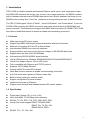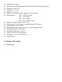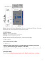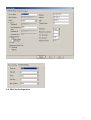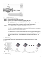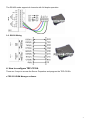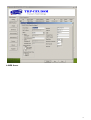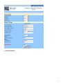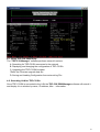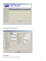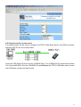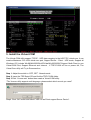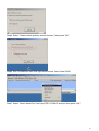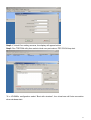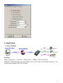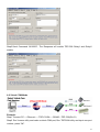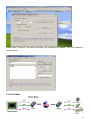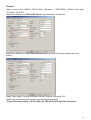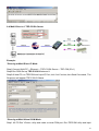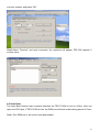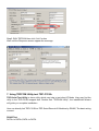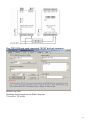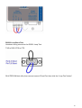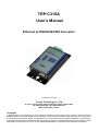
1
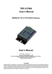
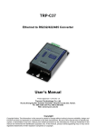
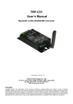
TRP-C31SA
User’s Manual
Ethernet to RS232/422/485 Converter
Printed Jan. 2010 Rev 1.1
Trycom Technology Co., Ltd
1F, No.2-11, Sihu street, Yingge Township, Taipei, Taiwan ROC
Tel: 886-2-86781191, Fax: 886-2-86781172
Web: www.trycom.com.tw
Copyright
Copyright Notice: The information in this manual is subject to change without prior notice in order to improve
reliability, design and function and dosed not represent a commitment on the part of the manufacturer. No part of this
manual may be reproduced, copied, or transmitted in any form without the prior written permission of manufacturer.
Acknowledgment Products mentioned in this manual are mentioned for identification purpose only. Products manes
appearing in this manual may or may not be registered trademarks or copyright of their respective companies.
1. Introduction
TRP-C31SA is suitable industrial environment Ethernet serial server, wide range power input ,
the RS422/485 interface with surge, over current ,over voltage protection, the RS485 interface
built-in hardware decoder ensure RS485 data without lost, Specify hardware can keep on line
RS485 device working fine; if user lost password or wrong setting can easy to back to factory.
The TRP-C31SA support “Direct IP Mode”, “Virtual COM Mode”, and “Paired Mode”. It has one
D-SUB 9 PIN serial port for RS232 connection and screw terminal block for RS422/485 and
power connector. The Ethernet port support Auto-MDIX and Auto-select 10/100MB. TRP-C31SA
also offers a Heart Beat feature to ensure a reliable communicating connection.
1-1 Features
z
z
z
z
z
z
z
z
z
z
z
z
z
z
z
z
z
z
Wide input range DC power supply.
Support Auto-MDIX twisted pair crossover detection and Auto-Correction.
Maximum Connection 8 Client PC at Server Mode.
Auto direction RS485 flow control by hardware.
Surge protection and over current and over voltage on RS-422/485 data lines.
Support baud rate from1200~921600Kbps.
Auto switching RS-232/422/485 signal interface
Virtual COM drivers for Windows 98/WIN2000/WIN XP/Vista/WIN2003/WIN 7.
Virtual Com Support Server, Client, UDP mode.
Fully compatible with Ethernet and TCP/IP protocol.
Supports 10/100 Mbps Ethernet.
Power/Link/RX/TX mode LED indicator.
Heart Beat function ensures a reliable communicating connection.
Auto Pair-mode when power or Ethernet cable fails.
Back to factory setting by external switch.
Support configuration by serial console.
Update the firmware by Ethernet.
Support screw terminal and standard external DC power adaptor.
1-2 Specification.
z
z
z
z
z
z
z
Power Input Voltage: DC +10V to +30V.
LAN: Auto-MDIX, 10/100 Mbps Auto-detecting.
RS-232: TX, RX, RTS, CTS, DTR, DSR, DCD, GND.
Virtual-Com mode support RS232 TXD,RXD,GND.
RS422 TX+,TX-,RX+,RX-.
RS485 DATA+,DATA-.
RS-422: TX+, TX-, RX+, RX-.
2
z
z
z
z
z
z
z
z
z
z
z
z
z
z
z
z
RS-485: Data +, Data –.
Data Rate: 1200,2400,4800,9600,19200,38400,57600,115200,921600 K bps .
Parity: none, even, odd.
Data Bits: 5, 6, 7 or 8.
Stop Bits: 1, 1.5 or 2.
Protocol: TCP, IP, ARP, DHCP, Telnet, HTTP, UDP, ICMP
External switch:
OFF OFF :TCP mode.
ON
OFF :Option .
OFF ON :Option.
ON
ON :Back to Factory.
Maximum connection with client PC :1~8.
Power supply: Screw terminal, or standard external DC adapter.
Serial interface: +/-15 KV ESD.
RS422/485 interface: Surge, over current, over voltage protection.
Power consumption: 12V/140mA.
Operating Temperature: 0 to 65 °C.
Humidity: 0~90% Non-Condensing.
Dimensions: 151(L)*75(W)*26(H) mm.
Weight: 395g.
2. Hardware Description
2-1. Panel layout
3
Notice: User can only choose either external DC-Jack or Screw terminal DC input. Do not use
external DC-Jack and screw terminal DC input simultaneously.
2-2. LED indicator
PWR LED: System is ready.(Blinking)
LINK LED: Ethernet cable connection and data active.
TX/RX LED: UART Transiting/Receiving Indicator.
DC Jack: Power DC Input from +10V to +30V. (Pleas use the 5.5*2.1mm DC JACK).
2-3. Reset Button
Push the reset button will Re-Boot.
2-4. DIP Switches
A double DIP switch allows the TRP-C31SA to be placed into TCP/Option/Factory Mode.
OFF OFF: Normal mode, ON OFF: Option, OFF ON : Option,
ON ON: When user lost the IP, forget password or wrong setting, and adjust this position will
back to factory.
2-5.Factory Setting
Factory Setting: *Adjust the external switch to ON ON will back to factory as bellow.
4
2-6. DB-9 Pin Configuration
5
3. Install TRP-C31SA Hardware
STEP1: Connect power source with TRP-C31SA.
STEP2: Connect TRP-C31SA with internet port by RJ45 LAN cable.
If the cable is properly connected the “LINK” LED will light up.
*The TRP-C31SA Support Auto-MDIX, A straight-through or crossover Ethernet
cable can be used to make a connection directly to the HUB/Router/PC.
STEP3: Connect TRP-C31SA with RS232 or RS422/485 serial device.
The TRP-C31SA has one DB-9 male connectors for RS232 connection and a screw
terminal connector for RS422/485 connection.
The DB-9 serial port is configured as a DTE (data terminal equipment) device. A null
modem cable is required to make a connection between the COM port on a PC and
the TRP-C31SA serial port. The screw terminal connector accepts AWG #12 ~30
wires.
3-1. RS485 Wiring
The RS-485 mode supports the Transmit and Receive channels using 2-wire half-duplex
operation.
3-2. RS422 Wiring
6
The RS-422 mode supports 4 channels with full duplex operation.
3-3. RS232 Wiring
4. How to configure TRP-C31SA
There are 3 ways to access the Server Properties and program the TRP-C31SA.
a.TRP-C3X DSM Manager software.
7
b.WEB Server
8
c. Serial Console.
9
4-1. Using TRP-C3X DSM Utility.
The “TRP-C3X Manager” software performs several functions:
A: Searching for TRP-C31SA connected to the network
B: Displaying and changing the configuration of TRP-C31SA
C: Upgrading the TRP-C31SA firmware.
*Refer the Firmware upgrade help file.
D: Saving and Loading Configuration from external log File.
4-2. Searching LAN for TRP-C31SA
Once TRP-C31SA is connected to the LAN the TRP-C3X DSM Manager software will search it
and display it in a window by name, IP address, Mac….Information.
10
4-3.Configuring Server Properties
Device Name
Device server name, Maximum 10 chars.
11
MAC Address
The Device server MAC address.
DHCP
When DHCP is disabled, the IP address, Subnet mask, Gateway can be manually assigned by
user, When DHCP enabled, IP address, Subnet mask, Gateway address will be dynamically
configuration by DHCP serve that cannot be changed by the user.
In “enable” status if a DHCP server is not available on the network ,the TRP-C31SA will time out
and back to default setting IP=192.168.1.1.
Server Listening IP
The serial device IP address.
Server Data listening port
UART Serial I/O port interface address.
Client Destination IP
When user using the paired mode, the client setting need to input Server IP and PORT which
one need to connect.
Client Destination port
UART Serial I/O address.
Port: 16 bit number. (1 ~ 65535)
Netmask
The default LAN Netmask is configured for a Class C address. This maybe reconfigured by the
user.
Gateway
Input the gateway IP address that can be allows users to access the serial server from internet.
DNS
Short for Domain Name System, an Internet service that translates domain names into IP
addresses. Because domain names are alphabetic, they're easier to remember. The Internet
however, is really based on IP addresses. Every time you use a domain name, therefore, a DNS
service must translate the name into the corresponding IP address.
Transmit timer:0~64 mS/Unit
Time interval to send out serial data char staring packet.
UART Transmit:0~15 uS/Unit
Time interval to send out serial data char packet.
Hear Beat: Disable /Enable
When Hear Beat enable, User can open a 5300 port, 5 sec interval to send out data char packet
that provides a easy way to ensure the communications between Host PC Client and server
devices.
Maximum Connection: 1~16
The function allows the user to configure the TRP-C31SA Serial Server to have up to 16 TCP
client connections.
TCP Keep Alive: 1~7 /Minute
When TRP-C31SA in Server mode, the TRP-C31SA without data over the 1~7 Min setting value,
12
The TRP-C31SA will be disconnecting TCP.
When TRP-C31SA in Client mode, the TRP-C31SA without data over the 1~7 Min setting value,
The TRP-C31SA will be reconnecting TCP.
New Password: 1234
1000~9999 integer, if input the wrong password over 5 times, the WEB-Page will lock until the
TRP-C31SA adjust the switch ON,ON then re-boot back to factory.
Firmware Version
Firmware Version.
Serial Port setting
Baud Rate: UART Speed from 1200,2400,4800,9600,19200,38400,57600,115200,921600 k bps
Data Bit: 5,6,7,8
Parity: Odd, Even, None
Stop Bits: 1, 1.5
Flow Control: Xon/Xoff, Hardware, None
Submit
Save the setting value to TRP-C31SA.
Save
Save the setting value to external file.
Load
Load the setting value to external file.
Upgrade
Upgrade the TRP-C31SA firmware
*Wrong way the upgrade firmware will cause the TRP-C31SA system fail.
4-4 using the WEB Server mode
Open the Web browser and input the IP of TRP-C31SA, the windows will appear the setting that
can be used to configure the TRP-C31SA.
Example:
If TRP-C31SA IP is 192.168.3.24 Please Input the 192.168.3.24 then enters, the
web-page will appear below.
13
4-5 Using the serial console mode
The serial console can be used to configure the TRP-C31SA Serial Server from DB-9 connector
link the HOST PC by null modem cable.
Insert the TRP-Serial CD then find the CONSOLE.exe, The CONSOLE file support all windows
O.S include MS-DOS, Run the CONSOLE file and Re-boot the TRP-C31SA then select correct
host COM port number and data format.
14
5. Install the Virtual-COM
The Virtual-COM utility support TCP/IP、UDP data mapping to the HOST PC virtual-com, it can
creative Maximum 512~1024 virtual-com port, Support Server、Client、UDP mode, Support all
Windows O.S include Win98/Win2000/WinXP/Vista/Win2003/WIN7,Support Multi-Client to one
Virtual-COM Port; Support Ethernet and Internet , If TRP-C31SA off line or power fail, The
Virtual-Com utility will Try to Reconnection.
Step 1. Adjust the switch to “OFF, OFF”. Normal-mode.
Step 2. Insert the TRP-Serial CD and find the TRP-C31SA folder.
Step 3.Click “Vcomm.exe” button then create a Virtual-COM utility.
*The Vcomm utility support multi-language ,please select which one do you need”
Step4. Click “OK” button and select “VSP run as Client support Server Device”.
15
Step5. Select “Create virtual serial by device scanner”, then press “OK”
Step6. Run VCOMM.exe then click right button select “New Virtual COM”
Step7. Select “Select Serial Port” and input TRP-C31SA IP and port then press “OK”.
16
Step8. If Virtual-Com setting success, the display will appear bellow.
Step9. Run TRPCOM utility then select virtual-com port make a TRP-C31SA loop test.
*If in VCOMM‘s configuration select “Boot with windows”, the virtual-com will Auto-connection
when windows start.
17
6. Application
6-1 Direct IP Mode
Example:
Step1: Connect PC-----Ethernet-----TRP-C31SA-----RS485---TRP-C28 (ID=01)
Step2.Run TRPCOM utility and input IP/Port, click “Link” button, then Send Command , The
Response will appear TRP-C28 I/O Status.
18
Step3.Send Command “#010003”, The Response will enable TRP-C28 Relay1 and Relay2
enable.
6-2 Virtual COM Mode
Example:
Step1. Connect PC-----Ethernet------TRP-C31SA-----RS485---TRP-C28(ID=01)
Step2. Run Vcomm utility and make a virtual-COM port, Run TRPCOM utility and input com port
number, press “OK”.
19
Step3.Select “Terminal” and send command, the response will appear TRP-C28 channel 2
counter value.
6-3 Paired Mode
20
Example:
Step1. Connect PC---RS232---TRP-C31SA-----Ethernet------TRP-C31SA----RS422 (loop back
TX+ÆRX+,TX-ÆRX-).
Step2.Run DSM set up TRP-C31SA Client, Input destination IP and Port.
Step3.Run DSM set up TRP-C31SA Server and be sure the IP and port as same as client
setting.
Step4. Open hyper Terminal and select com port number, and press “OK”.
Step5. key-in some chars the hyper terminal will show loop back.
*Try to disconnect power or RJ45 cable, the TRP-C31SA will Auto Re-connection.
21
6-4 Multi-Client to 1 TRP-C31SA Server
Example:
*Running at Multi-Direct IP Mode
Step1.Connect Multi-PC ---Ethernet----TRP-C31SA Server----TRP-C28 (ID=1)
Step2.Run DSM Set up TRP-C31SA Maximum 8.
Step3.All host PC run TRPCOM and input IP, Port, click “Link” button, then Send Command , The
Response will appear TRP-C28 I/O Status.
.
*Running at Multi-Virtual COM Mode
Step1. All PC Run VComm. utility and make a virtual-COM port, Run TRPCOM utility and input
22
com port number, and press “OK”.
Step3.Select “Terminal” and send command, the response will appear TRP-C28 channel 2
counter value.
6-5 Heart Beat
The heart Beat function help customer detection the TRP-C31SA on–line or off-line, User can
open one 5300 port, if TRP-C31SA on line, the 5300 port will send a char staring period of 5 sec.
Step1: Run DSM.exe to set up the heart beat enable.
23
Step2: RUN TRPCOM then click “Link” button
Wait until the Response screen appear the message
7. Using TRPCOM Utility test TRP-C31SA.
TRP-Serial Test Utility is demo utility which may help to test direct IP Mode .User may find the
utility in the TRP-C31SA support disk. Double click “TRPCOM Utility”, the installShield Wizard
will guide you complete installation.
User can directly link TRP-C31SA to TRP-Serial Remote IO Modules by RS485, The basic wiring
connect.
RS485 Test
DATA+ to DATA+,DATA- to DATA-
24
Run TRPCOM and send command “$01M” and get response.
RS422 Loop Test
Hardware wiring connection for RS422 loop test.
TX+ to RX+, TX- to RX-
25
RS232 Loop Back Test
Hardware wiring connection for RS232 Loop Test.
TXD to RXD, RTS to CTS.
RUN TRPCOM test utility then connect correct IP and Port then click the “Loop Test” button”
26
27