1
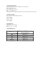
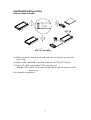
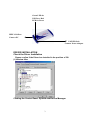
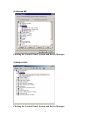
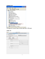
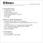
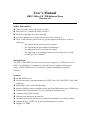
User’s Manual
IEEE 1394 to 2.5” IDE External Case
Version 1.0
Safety Instructions
Always read the safety instructions carefully
Keep this User’s Manual for future reference
Keep this equipment away from humidity
Lay this equipment on a reliable flat surface before setting it up
If any of the following situation arises, get the equipment checked by a service
technician:
o The equipment has been exposed to moisture
o The equipment has been dropped and damaged
o The equipment has obvious sign of breakage
o The equipment is not working properly or you cannot get it to work
according to User’s Manual
Introduction
The IEEE 1394 to IDE External Case allows you to upgrade 2.5” IDE disk drives to
IEEE 1394 ATAPI host commands. Provides the ability to upgrade and support a
variety of ATA/ATAPI based 2.5” disk drives without changing the peripheral
hardware.
Feature
64 MB RAM or more
Full interoperable with implementation of IEEE-1394 (1995) and IEEE 1394A-2000
compliant
Data transfer rates of 100/200/400 Mbps
Supports IDE PIO modes and DMA modes and Ultra DMA modes up to UDMA 100
External Flash ROM interface for easy updating the firmware code
Automatic Page Table fetching
Dedicated asynchronous data transfer
Automatic packing/de-packing for asynchronous transmit/receive data of DMA
Support 4k bytes of FIFO for bi-directional transmit/receive data
Support 2.5” HDD
System Requirements
IBM compatible Pentium-233MHZ or faster & MAC PC
64 MB RAM or more
Available IEEE 1394 Port
2.5” Hard Disk Drive
Systems with OS: MS Windows 98/ ME / 2000 / XP and MAC OS 8.6 or high
Package Contents
The 2.5” IEEE 1394 to IDE External Case
Power Adapter
IEEE 1394 Cable
PS/2 5V. Cable
User’s Manual
Specifications:
HDD Master mode only
IEEE 1394 to 2.5” HDD
SUPPORTED O.S.:
Functions IEEE 1394 to 2.5”IDE External Case
(Aluminum/Plastic)
O.S.
98SE
Build-In O.S.
ME
Build-In O.S.
2000
Build-In O.S.
XP
Build-In O.S.
Mac OS
Build-In O.S.
1
HARDWARE INSTALLATION
How to Install the HDD
Assembly
ED-125 Assembly
(1) Push a tip driver into the hole and push out ( to the left ) to open the
front cover
(2) Insert a HD ( hard disk ) into the connector of PCB ( PC board )
(3) Insert #2 ( HD connected to PCB ) into the case
Remark: The convex of the case should match with the concave of the
front cover.
(4) Assembly completed.
2
Green LED for
USB Port; Red
LED for Power
IEEE 1394 Port
Connect PC
POWER Jack
Connect Power Adapter
DRIVER INSTALLATION
Check the Driver Installation
Please confirm if the Driver has installed in the position of OS.
(1) Window 98se
Clicking the Control Panel. System and Device Manager.
3
(2) Window ME
Clicking the Control Panel. System and Device Manager.
(3)Window 2000
Clicking the Control Panel, System and Device Manager.
4
(4)Window XP
Clicking the Control Panel, System and Device Manager.
(5)Mac OS
5
The Installation has finished.
Check “Apple System Profiler\ Devices and Volumes\”
Certificate
FCC
This equipment has been tested and found to comply with Part 15 of the FCC
Rules. Operation is subject to the following two conditions:
(1) This device may not cause harmful interference
(2) This device must accept any interference received. Including interference
that may cause undesired operation.
CE – Certificate
This equipment is in compliance with the requirements of the following
regulations: EN 55 022: CLASS B
DISCLAIMER
Information in this document is subject to change without notice. The
manufacturer does not make any representations or warranties (implied or
otherwise) regarding the accuracy and completeness of this document and
shall in no event be liable for any loss of profit or any commercial damage,
including but not limited to special, incidental, consequential, or other damage.
No part of this document may be reproduced or transmitted in any form by any
means, electronic or mechanical, including photocopying, recording or
information recording and retrieval systems without the express written
permission of the manufacturer.
6