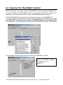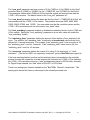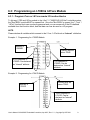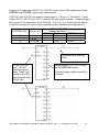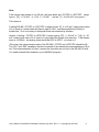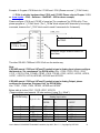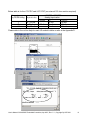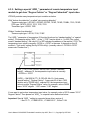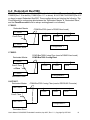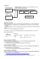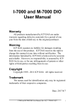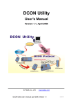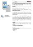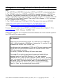
1
Chapter 6: Linking RS-485 I-7000 & I-87xx Modules
Note:
1. The I-87017R and I-87017RC is better than I-87017 and I-87017C in industrial application.
2. The I-87018Z is better than I-87018R and I-87018 in industrial application. (I-87018Z has
10-channels. The precision is better than I-87018R and I-87018 . And each channel can
configure to be different Input type and range. For example, using Ch.1 to 4 to measure 4 to 20
mA , using Ch.5 to 8 as Thermo-Couple K-Type, using Ch.9 to measure +/- 2.5 V, and using
Ch.10 as Thermo-Couple R-Type.)
3. The I-7018Z is better than I-7018R and I-7018. (The reason is the same as I-87018Z)
i-7018z: http://www.icpdas.com/products/Remote_IO/i-7000/i-7018z-g.htm
i-87018z: http://www.icpdas.com/products/Remote_IO/i-87k/i-87018z.htm
For more description about using I-87018Z and I-7018Z, please refer to Chapter 11.3.9 or
www.icpdas.com – FAQ – Software – ISaGRAF - 055.
Please refer to Section 1.5 for connection instructions between the I-8xx7 controller system to
the I-7000 and I-87xx series modules.
Very Important:
Please wire an terminal resistor around 110 to 330 ohms at I-7188EG/XG,
I-8xx7 or W-8xx7 controller ‘s RS-485 port , between the D+ and the D- pin
(or beween the RS-485+ and RS-485- pin).
This will ensure the host watchdog of I-7000 and I-87K output modules to work
correctly when the communication between the controller and the I-7000 /
I-87K output modules is broken.
(You can try 110 ohms first, then try 220 ohms, then others)
For example, if you don’t wire any terminal resistor and enable the host
watchdog function at “bus7000b” (Section 6.2 , the “host_watchdog”
parameter set as 1) , when you just un-plug the I-7000’s “DATA+” pin (keep
“Data-“ pin connected with the controller) , you will see the watchdog doesn’t
work in this i-7000. If you wire a resistor about 110 ohms between the
controller’s RS-485 D+ and D- pin, if you un-plug anyone of I-7000’s
“Data+” or “Data-“ pin, the watchdog will work correctly.
User’s Manual Of ISaGRAF Embedded Controllers, Apr.2007, Rev. 5.1 , Copyright By ICP DAS
1
6.1: Configuring The I-7000 & I-87xx Modules
Note:
A. If RS-485 remote I-7000 and I-87xxx I/O module’s type is Analog Input, please
configure the format as “2’s complement” by DCON utility. Like : I-7005, I-7013,I-7015,
I-7016, I-7017, I-7017R, I-7017RC, I-7018, I-7018R,I-7018Z, I-7019, I-7019R, I-7033, I-87013,
I-87015, I-87016, I-87017, I-87017R, I-87017RC, I-87018,I-87018R, I-87018Z and I-87019R.
B. If RS-485 remote I-7000 and I-87xxx I/O module’s type is Analog Output, please
configure the format as “Engineer Unit” by DCON utility.
Like : I-7021, I-7022, I-7024, I-87022, I-87024 and I-87026 .
To begin configuration of the I-7000 and I-87xx series modules to the controller system, use the
"DCON Utility" program to set up the I-7000 and I-87xx modules. Please use DCON utility of
version 4.4.3 or later version. (at ftp://ftp.icpdas.com/pub/cd/8000cd/napdos/driver/dcon_utility/
or I-8000 CD-ROM:\napdos\driver\dcon_utility\setup\ )
Notes:
1. Make sure the hardware connection is correct.
2. Search and configure the modules one by one.
3. Connect the module’s INIT* to GND and Power on the module.
User’s Manual Of ISaGRAF Embedded Controllers, Apr.2007, Rev. 5.1 , Copyright By ICP DAS
2
Step 1:
Hardware connection
A. The power supply must be DC power between +10V to +30V.
B. Wiring diagram for connecting to I-7000: (one module for each time)
Note:
For configuring I-7000 and I-87xxx I/O module, you have to prepare an I-7520R
converter. For other wiring diagram please refer to “DCON Utility User’s Manual”.
Step 2:
Set I/O module to initial state
If the module is a new one, factory have set a default settings for user’s convenient.
If you don’t know the configuration of the module, please set the I/O module to initial
state.
*** To set I-7000 module to initial state is to wire connect the INIT* to GND and
Power on the module. Then the module will become initial state. (Some new
designed I-7000 modules have a Dip-switch at its back. Please switch it to
the “INIT” position , then power up the module)
*** I-87K module’s initial state is set by I-87K4 / 5 / 8 / 9 ’s dip switch. For example,
setting dip-2 to “ON”, and then re-cycle the power, it means the second slot is in
initial state. (If using I-87K5 and I-87K9, please do not plug I-87xxx board in its
left-most slot for initial configuration . Please plug at 2nd to 9th slot for initial
configuration. The dip-1 is for 2nd slot of I-87K5 and I-87K9, …, dip-4 is for 5th
slot, Dip-8 is for 9th slot of I-87K9). Some new designed I-87K I/O modules
have dip-switch built-in. Their “INIT / Normal” state is controlled by its
own dip-switch not by the dip-switch of I-87K4 / 5 / 8 / 9 .
User’s Manual Of ISaGRAF Embedded Controllers, Apr.2007, Rev. 5.1 , Copyright By ICP DAS
3
The default state from factory:
I/O Module
i-7000
M-7000
87K series
Address
1
1
1
Baud rate
9600
9600
115200
Checksum
Disabled
Not defined
Disabled
Protocol
DCON
Protocol
Modbus
Protocol
DCON Protocol
The initial state after initiation:
Step 3:
I/O Module
7000 series (i-7000 and M-7000)
87K series
Address
0
0
Baud rate
9600
115200
Checksum
Disabled
Disabled
Protocol
DCON Protocol
DCON Protocol
Select COM port and baud rate to search
Execute the DCON Utility from “Start/programs/DAQPro/DCON Utility/”.
1. Click “COM Port” menu to select the COM port and baud rate to search. You can
select multi-baud rate, protocol or checksum conditions if you do not know the
module’s setting, but it will spend more time to scan the network. After selection,
click “OK”.
2. Click
“Start Search” icon to begin search module. Click
when it is found.
User’s Manual Of ISaGRAF Embedded Controllers, Apr.2007, Rev. 5.1 , Copyright By ICP DAS
4
1
2
Step 4:
Click Searched module ID and give the new configuration
1
2
3
User’s Manual Of ISaGRAF Embedded Controllers, Apr.2007, Rev. 5.1 , Copyright By ICP DAS
5
Then follow the
steps to check the
new setting.
Note:
Remember to remove the connection of I-7000’s INIT* and GND after the setting is
well configured. Then recycle its power.
For I-87K I/O, remember to switch the related Dip to “OFF”, then recycle its power.
IMPORTANT NOTES Regarding remote I-7000 & I-87xx Modules:
One I-8xx7, I-7188EG/XG controller system can link up to a maximum of 64 pcs. of I-7000 and
I-87xx modules (However 255 pcs for W-8xx7). It is recommended though that you do not
link more than 24 modules to a single I-8xx7 and 7188EG/XG , while 64 modules for a W-8xx7
controller system. Each I-7000 and I-87xx module MUST have it’s own unique address to
properly link to an ISaGRAF controller system. The default "Checksum" setting is
disabled (If set as enabled, please connect “bus7000b” listed in section 6.2 and set
“checksum” parameter to 1), and make sure that all of the I-7000 and I-87xx modules are
set to the same baud rate and same checksum setting as the controller system (9600
baud by default).
When you receive any of the I-7000 series modules or I-87xxx modules you will receive
documentation called "Getting Started With I-7000 Series Modules" that provides instructions
on how to properly configure these modules. If you need assistance on changing the baud rate
or checksum, please refer to the "Change Baud Rate & Checksum" section in the "Getting
Started With I-7000 Series Modules". You can find all of the documentation on the CD provided
with your I-7000 series module from ICP DAS in a file titled "getstart.pdf".
If RS-485 remote I-7000 and I-87xxx I/O module’s type is Analog Input, please configure
the format as “2’s complement” by DCON utility. Like : I-7005, I-7013,I-7015, I-7016,
I-7017, I-7017R, I-7017RC, I-7018, I-7018R,I-7018Z, I-7019, I-7019R, I-7033, I-87013, I-87015,
I-87016, I-87017, I-87017R, I-87017RC, I-87018,I-87018R, I-87018Z and I-87019R.
If RS-485 remote I-7000 and I-87xxx I/O module’s type is Analog Output, please
configure the format as “Engineer Unit” by DCON utility.
Like : I-7021, I-7022, I-7024, I-87022, I-87024 and I-87026 .
User’s Manual Of ISaGRAF Embedded Controllers, Apr.2007, Rev. 5.1 , Copyright By ICP DAS
6
6.2: Opening The "Bus7000b" Function
To create a link between the I-8xx7, I-7188EG/XG & W-8xx7 controller system and an I-7000
and I-87xx module, you need to connect the "Bus7000b" function through the "ISaGRAF I/O
Connection" window. The "Bus7000b" function is considered a "virtual board", and must be
selected from the "Equipments" section of the "Select Board/Equipment" window.
The "Bus7000b" MUST be connected to slot number 8 or higher on the "ISaGRAF I/O
Connection" window (since slot 0 through 7 are used to connect to real I-8000 boards). Only
one "Bus7000b" can be linked to one I-8xx7, I-7188EG/XG & W-8xx7 controller system!
If you attempt to connect more than one "Bus7000b" to an ISaGRAF controller, it will not work.
In the example provided, set the slot below number 9 to "Bus7000b: Remote".
Com_port setting:
I-8xx7: 3 or 4 (COM3 or COM4)
I-7188EG/XG: 2 or 3
W-8xx7: 3
User’s Manual Of ISaGRAF Embedded Controllers, Apr.2007, Rev. 5.1 , Copyright By ICP DAS
7
The "com_port" parameter can have a value of 3 (for COM3) or 4 (for COM4) for the I-8xx7
controller, while 2 (COM2) or 3(COM3) for the I-7188EG/XG, and 3 (COM3) for the W-8xx7.
This parameter defines which COM port ID the controller system will communicate with the
I-7000 / I-87xx module. The default value for the "com_port" parameter is 3.
The "com_baud" parameter defines the baud rate that the I-8xx7, I-7188EG/XG & W-8xx7 will
communicate with the I-7000 / I-87xx module. The possible values are 2400, 4800, 9600,
19200, 38400, 57600, and 115200. You must make sure that the controller system and the
I-7000 / I-87xx modules are all set to the same "com_baud" value.
The "host_watchdog" parameter enables or disables the watchdog function for the I-7000 and
I-87xx module. Setting the "host_watchdog" parameter to a non-zero value will enable the
"host_watchdog" feature.
The "watchdog_timer" parameter defines the amount of time before a "host_watchdog" will
occur. The value for the "watchdog_timer" is defined in a hexadecimal value with the units
defined in 0.1-second increments. For example, if the "watchdog_timer" is set to a value of 1E,
the "watchdog_timer" is set for 3 seconds. If the "watchdog_timer" value is set to 2A, the
"watchdog_timer" is set for 4.2 seconds.
The “checksum” parameter defines the remote IO is using “0: No checksum” or “1:with
checksum”. (The old “bus7000” not supporting “checksum” options. Bus700b does support it)
If the host watchdog feature is active and the watchdog timer is exceeded on the controller
system (it means the connection is break between the controller and I-7000 / I-87xx modules),
the I-7000 / I-87xx modules will go to a "safe" predetermined value by DCON utility. Normally
for Digital Output channel, the “safe” state is D/O=OFF or D/O=False.
There is an analog input channel available on the "Bus7000b: Remote" virtual board. This
analog input channel will return a value equal to the currently set baud rate.
User’s Manual Of ISaGRAF Embedded Controllers, Apr.2007, Rev. 5.1 , Copyright By ICP DAS
8
6.3: Programming an I-7000 & I-87xxx Module
6.3.1: Program I-7xxx or I-87xxx remote IO function blocks
To link any I-7000 and I-87xx module to the I-8xx7, I-7188EG/XG & W-8xx7 controller system,
the "Bus7000b" module MUST be opened first. Once the "Bus7000b" is opened, the "I_7xxx" /
“I-87xx” function block can now be programmed and you can access all of the I/O channels
available from that function block, and that data can now be used in a LD program.
NOTE:
Please declare all variables which connect to the I-7xxx / I-87xx block as “Internal“ attribution.
Example 1: Programming An I-7050D Module
Address of
I-76050D
Connect well will
return TRUE.
8 D/O channels of
I-7050D. Can declared
as “Internal” attribute.
7 D/I channels of
I-7050D. Can be
declared as “Internal”
attribute.
Example 2: Programming An I-7041D Module
Address of
I-7041D
Connect well will
return TRUE.
14 D/I channels of
I-7041D. Can be
declared as “Internal”
attribute.
User’s Manual Of ISaGRAF Embedded Controllers, Apr.2007, Rev. 5.1 , Copyright By ICP DAS
9
Example 3: Programming a I-87017R or I-7017RC function block (The hardware should be
i-87017RC and i-7017RC, current input measurement)
I-87017RC and I-7017RC can measure current input of ± 20 mA , 0 ~ 20mA and 4 ~ 20mA.
Unlike I-87017, I-87017R and I-7017, no external 125 ohm resistor required . Please configure
their format as “2’s complement” by DCON utility. (The “A4_20_to” function can be used to
convert the analog input value to user’s engineering value, please refer to Appendix A.4)
Range type
(by “DCON Utility”) Physical value
7
D
1A
4 ~ 20 mA
± 20mA
0 ~ 20 mA
I-7017RC /87017RC
Analog Input value
- 32768
0
4 mA
- 20mA
0 mA
0 mA
+32767
20 mA
20mA
20 mA
If connected well, return as
TRUE.
To use “i_87017R”
and “i_7017RC” ,
Please assign the
same “Range Type”
setting here as they
are configured in the
DCON utility.
Please program “i_87017R” for using
RS-485 I-87017RC module.
8 Internal Integer variables should be
used here
User’s Manual Of ISaGRAF Embedded Controllers, Apr.2007, Rev. 5.1 , Copyright By ICP DAS
10
Note:
If the current input sensor is 4 to 20 mA, user may better set I-7017RC or I-87017RC ‘ range
type to “[D] : +/- 20 mA” , or “[1A] : 0 ~ 20 mA” . (set as " [7] : 4 to 20 mA" is not good )
The reason is :
If setting RS-485 I-7017RC or I-87017RC ‘s range type as “[7] : 4 to 20 mA”, analog Input value
of 0 or close to 0 could mean the Sensor input is 4 mA , and also possible the Sensor is
broken-line. So it is not easy to distinguish these two situation by software.
Howevr, if setting I-7017RC or I-87017RC ‘s range type as “[D] : +/- 20 mA” or “[1A] : 0 ~ 20
mA”, analog input value of 0 or close to 0 only means the Sensor is broken-line . If the Sensor
input is 4 to 20mA , the analog value should be 6553 to 32767 , not close to 0.
(Of course, the communication state of the RS-485 I-7017RC and I-87017RC should be Ok.
The “Ok1” and “OK2” variable in the above example 3 can indicate the communication is Ok or
not. If the communication is False, it means the controller can not link to the RS-485 I/O well.
You need to handle this situation in your ISaGRAF program).
User’s Manual Of ISaGRAF Embedded Controllers, Apr.2007, Rev. 5.1 , Copyright By ICP DAS
11
Example 4: Program I-7018 block for i-7018R and i-7018 (Please use new “i_7018n” block)
( i-7018z is a better hardware than i-7018 and i-7018R. Please refer to Chapter 11.3.9
or www.icpdas – FAQ – Software – ISaGRAF – 055 for demo example)
Please configure I-7018 and I-7018R ‘s format as “2’s complement” by DCON utility. Then
please program a “I_7018n” block (The “I_7018n” block request all 8-channels by one single
command, however the “I_7018” block need to send 8 commands for 8-channels)
If connected well, return
as TRUE.
Address of
I-7018 or 7018R
8 Internal Integer variables should be
used here
The other RS-485 I-7000 and I-87K I/O all use the similar way.
Note:
If RS-485 remote I-7000 and I-87xxx I/O module’s type is Analog Input, please configure
the format as “2’s complement” by DCON utility. Like : I-7005, I-7013,I-7015, I-7016,
I-7017, I-7017R,I-7018, I-7018R,I-7018Z, I-7019, I-7019R, I-7033, I-87013, I-87015, I-87016,
I-87017, I-87017R, I-87018,I-87018R, I-87018Z and I-87019R.
If RS-485 remote I-7000 and I-87xxx I/O module’s type is Analog Output, please
configure the format as “Engineer Unit” by DCON utility.
Like : I-7021, I-7022, I-7024, I-87022, I-87024 and I-87026 .
Below table is for the I-7017, 7017R, 87017, 87017R.
(These modules need external 125 ohm resistor if using “D: ± 20mA”)
Range tyep
I-7017 / 87017
(by DCON Utility)
Analog Input value
Physical value
-32768
0
+32767
8
9
A
B
C
D
± 10V
± 5V
± 1V
± 500mV
± 150mV
± 20mA
- 10V
- 5V
- 1V
- 500mV
- 150mV
- 20mA
0V
0V
0V
0mV
0mV
0mA
+ 10V
+ 5V
+ 1V
+ 500mV
+ 150mV
+ 20mA
User’s Manual Of ISaGRAF Embedded Controllers, Apr.2007, Rev. 5.1 , Copyright By ICP DAS
12
Below table is for the i-7017RC and i-87017RC (no external 125 ohm resistor required)
Range type
(by DCON Utility) Physical value
7
D
1A
4 ~ 20 mA
± 20mA
0 ~ 20 mA
I-7017RC / 87017RC
Analog Input value
- 32768
0
+32767
4 mA
20 mA
- 20mA
0 mA
20mA
0 mA
20 mA
Please refer to the on-line help for each I/O module’s table or refer to the Appendix D.
User’s Manual Of ISaGRAF Embedded Controllers, Apr.2007, Rev. 5.1 , Copyright By ICP DAS
13
6.3.2: Setting a special “ADR_” parameter of remote temperature input
module to get clear “Degree Celsius” or “Degree Fahrenheit” input value
ICPDAS provides many temperature input modules as below.
With “broken-line detection” or called “wire opening detection”
Thermocouple type: I-87018Z, I-87018R, 87019R, 7018Z, 7018R, 7018BL, 7019, 7019R
RTD type: I-87013, 87015, 7013, 7015, 7033
Thermister type: I-87005, 7005
Without “broken-line detection”
Thermocouple type: I-87018, 7018, 7018P
The “ADR_” parameter of temperature IO function block can be “standard setting” or “special
setting”. For example setting “ARD_” of the “I_7033” function block to 1 to 255 (Dec. value)
means “standard setting”, the value of 1 to 255 indicates the address of the remote I-7033. The
temperature input value is normally –32768 to + 32767 in the case. It depends on the IO
module’s “Type code” setting (Set by DCON utility). (normally value of –32768 & +32767
means wire “broken-line” )
ADR_ = 10 (TT=00, RR=00, AA=0A, Hex.) means “standard
setting”, address=10, the temperature input value is normally
–32768 to + 32767
If ADR_= 16#10201A (TT=10, RR=20, AA=1A, Hex) means
“special setting”, “Degree Celsius”, “type code=20 of this I-7033
module set by DCON utility”, address=26, the temperature input
value is a clear “Degree Celsius” value, for example, value of 4556
mans “45.56” degree. “-500” means “-5.00” degree.
If user want to get a clear temperature input value, for example, value of 2312 means “23.12”
Degree Celsius. Then please set “ADR_” to a special value defined as below.
Important: Special “ADR_” setting is supported since driver version of
I-8xx7:3.11 , I-7188EG:2.09 , I-7188XG:2.07 , W-8xx7:3.24
User’s Manual Of ISaGRAF Embedded Controllers, Apr.2007, Rev. 5.1 , Copyright By ICP DAS
14
Format: TTRRAA (Hex.)
TT=10 (Convert to "Degree Celsius")
TT=20 (Convert to "Degree Fahrenheit")
TT=00 (standard setting, -32768 to +32767. RR should be set as 00 if TT=00)
RR: "type code" setting of the related temperature input module
AA: address of the related temperature input module
For example, setting "ADR_" as
A. 16#102011 : (TT=10, RR=20, AA=11, Hex) the input value will be "Degree Celsius", unit is
0.01 degree, range= "20 : Platinum 100, a=0.00385, degree Celsius", address=17(Dec.).
That results input value of "2356" = 23.56 Degree Celsius, "-489" = -4.89 Degree Celsius,
"999990" = sensor broken-line.
B. 16#202A03 : (TT=20, RR=2A, AA=03, Hex)) the input value will be "Degree Fahrenheit", unit
is 0.01 degree, range= "2A : Platinum 1000, a=0.00385, degree Celsius", address=3(Dec.).
That results input value of "4512" = 45.12 Degree Fahrenheit, "500" = 5.00 Degree
Fahrenheit, "999990" = sensor broken line.
C. 16#01 : (TT=00, RR=00, AA=1) standard setting, the input value will be , -32768 to +32767,
address=1
User’s Manual Of ISaGRAF Embedded Controllers, Apr.2007, Rev. 5.1 , Copyright By ICP DAS
15
6.4: Redundant Bus7000
W-8x37 and W-8x47 support better CPU redundant solutions. Please refer to Chapter 20.
7188EG(Rev.1.19 or above), 7188XG(Rev.1.17 or above) & I-8417/8817/8437/8837(Rev.2.27
or above) support Redundant Bus7000. These configurations are listed as the following. The
Fbus/Ebus are for exchanging data between the “Redundant Master” & “Redundant Slave”,
and the Fbus/Ebus cable must be always working(break is not allowed).
I-7188XG:
Redundant Master
COM3:Bus7000 (need a RS485 Xxxx board)
I-7188XG
Com2:Fbus
I-7000
I-7000
I-87K
I-7188XG
Configuration 1
Redundant Slave
I-7188EG:
Redundant Master
COM3:Bus7000 if using Fbus (need a RS485 Xxxx board)
COM2:Bus7000 if using Ebus
I-7188EG
Com2: Fbus
or Ebus
I-7000
I-7000
I-87K
I-7188EG
Configuration 2
Redundant Slave
I-8417/8817:
Redundant Master
COM4:Bus7000 if using Fbus (need a RS232/485 Conveter)
I-8417/8817
I-7000
I-7000
I-87K
Com3: Fbus
I-8417/8817
Configuration 3
Redundant Slave
User’s Manual Of ISaGRAF Embedded Controllers, Apr.2007, Rev. 5.1 , Copyright By ICP DAS
16
I-8437/8837:
Redundant Master
COM4:Bus7000 if using Fbus (need a RS232/485 Convetor)
COM3:Bus7000 if using Ebus
I-8437/8837
I-7000
I-7000
I-87K
Com3: Fbus
or Ebus
Configuration 4
I-8437/8837
Redundant Slave
Operations Principle:
When the system is powered up, the control right of Bus7000 belong to “Redundant Master”.
If “Redundant Master” is dead(Power off), “Redundant Slave” takes over the control right of
Bus7000.
If “Redundant Master” is alive from dead (power up again), it takes over the control of Bus7000
again.
User’s control data is exchanging via Fbus or Ebus.
The “i7000_en” can be used to Enable/Disable the control right of Bus7000. The system’s
default status is Enable.
Parameter:
EN_7000_ integer
Return:
Q_
boolean
True: Enable, False: Disable
Always return True.
Demo example for I-7188XG:
The demo project uses “Configuration 1” and located at demo_48a & demo_48b.
It can be download at ICP DAS’s ftp site.
ftp://ftp.icpdas.com/pub/cd/8000cd/napdos/isagraf/7188xg/demo/
Demo example for I-7188EG:
The demo project uses “Configuration 2” with Ebus and located at demo_51a & demo_51b.
It can be download at ICP DAS’s ftp site.
ftp://ftp.icpdas.com/pub/cd/8000cd/napdos/isagraf/7188eg/demo/
Demo example for I-8437/8837:
The demo project uses “Configuration 4” with Ebus and located at demo_49a & demo_49b.
It can be download at ICP DAS’s ftp site.
ftp://ftp.icpdas.com/pub/cd/8000cd/napdos/isagraf/8000/demo/
User’s Manual Of ISaGRAF Embedded Controllers, Apr.2007, Rev. 5.1 , Copyright By ICP DAS
17