1
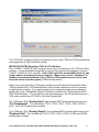
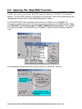
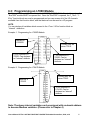
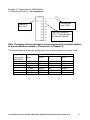
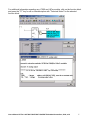
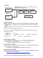
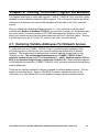
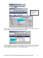
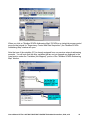
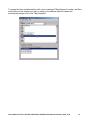
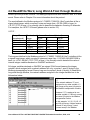
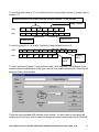
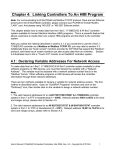
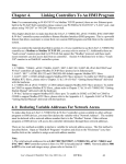
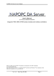
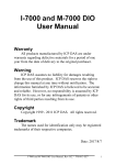
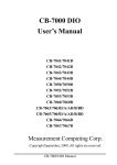
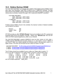
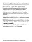
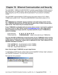
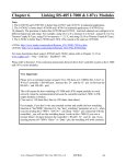
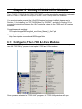
Chapter 6: Linking I-7000 & I-87xx Modules
The I-7188EG, 7188XG & I-8417/8817/8437/8837 controller provides the capability to integrate
with ICP DAS’s I-7000 and I-87xx (87K4 / 87K5 / 87K8 / 87K9) series I/O modules.
You must first make sure that the I-8xx7 I/O libraries have been installed, please refer to
Section 1.2 for Installing The “ICP DAS Utilities For ISaGRAF”, and refer to Section 1.5 for
connection instructions between the I-8xx7 controller system to the I-7000 and I-87xx series
modules.
Complete manual resides at
CD:\napdos\isagraf\8000\english_manu\User_Manual_I_8xx7.pdf
Or can be download at
http://www.icpdas.com/products/8000/isagraf.htm
6.1: Configuring The I-7000 & I-87xx Modules
To begin configuration of the I-7000 and I-87xx series modules to the I-8xx7 controller system,
use the "7000 Utility" program to set up the I-7000 and I-87xx modules.
Once you have selected the "7000 Utility" program, the "7000 Utility" window will open.
User’s Manual Of The I-8417/8817/8437/8837 ISaGRAF Embedded Controllers, 2002, V2.0
1
The "7000 Utility" program will go out and attempt to link to any I-7000 and I-87xx modules that
are plugged into an I-8xx7 controller system.
IMPORTANT NOTES Regarding I-7000 & I-87xx Modules
One I-7188EG, 7188XG & I-8xx7 controller can link up to a maximum of 64 I-7000 and I-87xx
modules. It is recommended though that you do not link more than 40 modules to a single I7188EG, 7188XG & I-8xx7 controller. Each I-7000 and I-87xx module MUST have it’s own
unique address to properly link to an controller. Make sure to set the "Checksum" to
disabled, and make sure that all of the I-7000 and I-87xx modules are set to the same
baud rate as the controller system (19200 baud by default).
When you receive any of the I-7000 series modules you will receive documentation called
"Getting Started With I-7000 Series Modules" that provides instructions on how to properly
configure these modules. If you need assistance on changing the baud rate or checksum,
please refer to the "Change Baud Rate & Checksum" section in the "Getting Started With I7000 Series Modules". You can find all of the documentation on the CD provided with your I7000 series module from ICP DAS in a file titled "getstart.pdf".
The I-7000 and I-87xx "Analog Input" type modules MUST have their data format set to
"2’s Complement". This includes the I-7013, I-7016, I-7017, I-7018, I-7033, I-87013, I87017, and I-87018 analog input modules.
The I-7000 and I-87xx "Analog Output" type modules MUST have their data format set to
"Engineer Unit". This includes the I-7021, I-7022, I-7024, I-87022, I-87024 and I-87026
analog output modules.
User’s Manual Of The I-8417/8817/8437/8837 ISaGRAF Embedded Controllers, 2002, V2.0
2
6.2: Opening The "Bus7000" Function
To create a link between the I-7188EG, 7188XG & I-8xx7 controller and an I-7000 and I-87xx
module, you need to connect the "Bus7000" function through the "ISaGRAF I/O Connection"
window. The "Bus7000" function is considered a "virtual board", and must be selected from the
"Equipments" section of the "Select Board/Equipment" window.
The "Bus7000" MUST be connected to slot number 8 or higher on the "ISaGRAF I/O
Connection" window (since slot 0 through 7 are used to connect to real I-8000 boards). Only
one "Bus7000" can be linked to one I-7188EG, 7188XG & I-8xx7 controller! If you attempt
to connect more than one "Bus7000" to an I-7188EG, 7188XG & I-8xx7 controller, it will not
work.
In the example provided, set the slot below number 9 to "Bus7000: Remote".
User’s Manual Of The I-8417/8817/8437/8837 ISaGRAF Embedded Controllers, 2002, V2.0
3
The "com_port" parameter can have a value of 3 (for COM3) or 4 (for COM4). This parameter
defines which COM port ID the I-7188EG, 7188XG & I-8xx7 controller will communicate with
the I-7000 / I-87xx module.
The "com_baud" parameter defines the baud rate that the I-8xx7 will communicate with the I7000 / I-87xx module. The possible values are 2400, 4800, 9600, 19200, 38400, 57600, and
115200. You must make sure that the I-7188EG, 7188XG & I-8xx7 controller and the I-7000 /
I-87xx modules are all set to the same "com_baud" value.
The "host_watchdog" parameter enables or disables the watchdog function for the I-7000 and
I-87xx module. Setting the "host_watchdog" parameter to a non-zero value will enable the
"host_watchdog" feature.
The "watchdog_timer" parameter defines the amount of time before a "host_watchdog" will
occur. The value for the "watchdog_timer" is defined in a hexadecimal value with the units
defined in 0.1-second increments. For example, if the "watchdog_timer" is set to a value of 1E,
the "watchdog_timer" is set for 3 seconds. If the "watchdog_timer" value is set to 2A, the
"watchdog_timer" is set for 4.2 seconds.
If the host watchdog feature is active and the watchdog timer is exceeded on I-7188EG,
7188XG & I-8xx7 controller system (it means the connection is break between the I-7188EG,
7188XG & I-8xx7 controller and I-7000 / I-87xx modules), the I-7000 / I-87xx modules will go to
a "safe" predetermined value.
There is an analog input channel available on the "Bus7000: Remote" virtual board. This
analog input channel will return a value equal to the currently set baud rate.
User’s Manual Of The I-8417/8817/8437/8837 ISaGRAF Embedded Controllers, 2002, V2.0
4
6.3: Programming an I-7000 Module
To link any I-7000 and I-87xx module to the I-7188EG, 7188XG & I-8xx7 controller system, the
"Bus7000" module MUST be opened first. Once the "Bus7000" is opened, the "I_7xxx" / “I87xx” function block can now be programmed and you can access all of the I/O channels
available from that function block, and that data can now be used in a LD program.
NOTE:
You can declare all variables which connect to the I-7xxx / I-87xx function block as
“Internal“ attribution.
Example 1: Programming An I-7050D Module
Address of
I-76050D
Connect well will
return TRUE.
8 D/O channels of I7050D. Can declared
as “Internal” attribute.
7 D/I channels of I7050D. Can be
declared as “Internal”
attribute.
Example 2: Programming An I-7041D Module
Address of
I-7041D
Connect well will
return TRUE.
14 D/I channels of
I-7041D. Can be
declared as “Internal”
attribute.
Note: The above internal variables can be assigned with a network address
to become Modbus variables. (Please refer to Chapter 4)
User’s Manual Of The I-8417/8817/8437/8837 ISaGRAF Embedded Controllers, 2002, V2.0
5
Example 3: Programming An I-7017 Module
The Data Format Used Is: 2’s Complement
If connect well,
return TRUE
Address of
that I-7017
The 8 A/I channels of
I-7017. Can be declared
as “Internal” attribute.
Note: The above internal variables can be assigned with a network address
to become Modbus variables. (Please refer to Chapter 4)
The following table describes the scaling factor from an analog signal to an integer value.
Range ID
(set by using
7000 Utility)
8
9
A
B
C
D
Electrical
range
Value in I-7017 block (decimal)
-32768
0
+32767
± 10V
± 5V
± 1V
± 500mV
± 150mV
± 20mA
- 10V
- 5V
- 1V
- 500mV
- 150mV
- 20mA
0V
0V
0V
0mV
0mV
0mA
+ 10V
+ 5V
+ 1V
+ 500mV
+ 150mV
+ 20mA
User’s Manual Of The I-8417/8817/8437/8837 ISaGRAF Embedded Controllers, 2002, V2.0
6
For additional information regarding any I-7000 and I-87xx module, click on the function block
and press the "F1" key for an on-line description with "Technical Notes" for the selected
function block.
User’s Manual Of The I-8417/8817/8437/8837 ISaGRAF Embedded Controllers, 2002, V2.0
7
6.4: Redundant Bus7000
7188EG(Rev.1.19 or above), 7188XG(Rev.1.17 or above) & I-8417/8817/8437/8837(Rev.2.27
or above) support Redundant Bus7000. These configurations are listed as the following. The
Fbus/Ebus are for exchanging data between the “Redundant Master” & “Redundant Slave”,
and the Fbus/Ebus cable must be always working(break is not allowed).
I-7188XG:
Redundant Master
COM3:Bus7000 (need a RS485 Xxxx board)
I-7188XG
Com2:Fbus
I-7000
I-7000
I-87K
I-7188XG
Configuration 1
Redundant Slave
I-7188EG:
Redundant Master
COM3:Bus7000 if using Fbus (need a RS485 Xxxx board)
COM2:Bus7000 if using Ebus
I-7188EG
Com2: Fbus
or Ebus
I-7000
I-7000
I-87K
I-7188EG
Configuration 2
Redundant Slave
I-8417/8817:
Redundant Master
COM4:Bus7000 if using Fbus (need a RS232/485 Conveter)
I-8417/8817
I-7000
I-7000
I-87K
Com3: Fbus
I-8417/8817
Configuration 3
Redundant Slave
User’s Manual Of The I-8417/8817/8437/8837 ISaGRAF Embedded Controllers, 2002, V2.0
8
I-8437/8837:
Redundant Master
COM4:Bus7000 if using Fbus (need a RS232/485 Convetor)
COM3:Bus7000 if using Ebus
I-8437/8837
I-7000
I-7000
I-87K
Com3: Fbus
or Ebus
I-8437/8837
Configuration 4
Redundant Slave
Operations Principle:
When the system is powered up, the control right of Bus7000 belong to “Redundant Master”.
If “Redundant Master” is dead(Power off), “Redundant Slave” takes over the control right of
Bus7000.
If “Redundant Master” is alive from dead (power up again), it takes over the control of Bus7000
again.
User’s control data is exchanging via Fbus or Ebus.
The “i7000_en” can be used to Enable/Disable the control right of Bus7000. The system’s
default status is Enable.
Parameter:
EN_7000_ integer
True: Enable, False: Disable
Return:
Q_
boolean
Always return True.
Demo example for I-7188XG:
The demo project uses “Configuration 1” and located at demo_48a & demo_48b.
It can be download at ICP DAS’s ftp site.
ftp://ftp.icpdas.com/pub/cd/8000cd/napdos/isagraf/7188xg/demo/
Demo example for I-7188EG:
The demo project uses “Configuration 2” with Ebus and located at demo_51a & demo_51b.
It can be download at ICP DAS’s ftp site.
ftp://ftp.icpdas.com/pub/cd/8000cd/napdos/isagraf/7188eg/demo/
Demo example for I-8437/8837:
The demo project uses “Configuration 4” with Ebus and located at demo_49a & demo_49b.
It can be download at ICP DAS’s ftp site.
ftp://ftp.icpdas.com/pub/cd/8000cd/napdos/isagraf/8000/demo/
User’s Manual Of The I-8417/8817/8437/8837 ISaGRAF Embedded Controllers, 2002, V2.0
9
Chapter 4: Linking To An HMI Program Via Modbus
This chapter details how to make data from the I-7188EG, 7188XG & I-8xx7 controller system
available to Human Machine Interface (HMI) programs. This is a powerful feature that allows
customers to create their own custom HMI programs and link them to the I-8xx7 controller
system
After you realize the material described in section 4.1, if you would like to use the I-8xx7
controller as a Modbus or Modbus TCP/IP I/O, you may refer to section 4.3. Additionally there
are "touch screen" monitors provided by ICP DAS that support the "Modbus" protocol, and
these touch screen monitors can also access data from an I-8xx7 controller system. Section
4.4 illustrates how to link a "Touch 510" monitor to an I-8xx7 controller system.
4.1: Declaring Variable Addresses For Network Access
To make data from an I-7188EG, 7188XG & I-8xx7 controller system available to other
software programs or HMI devices, you must first declare the variable with a "Network
Address". The variable must be declared with a network address number that is in the
"Modbus" format. The valid network addresses for an I-7188EG, 7188XG & I-8xx7
controller system is from 1 to FFF in hexadecimal (1 ~ 4095). Network address 5001 to
8072 is for word and integer arrays, please refer to Section 4.5. Other software programs
or HMI devices will access the I-7188EG, 7188XG & I-8xx7 controller information through these
network addresses.
There are two methods available to declare a variable for network address access. The first
method is described below. Open an "ISaGRAF Programs" windows and click on the
"Dictionary" icon, then double click on the variable to assign a network address number.
User’s Manual Of The I-8417/8817/8437/8837 ISaGRAF Embedded Controllers, 2002, V2.0
10
Note:
The value displayed
here is always in
hexadecimal.
When you click on the "Store" button you will see that "ISaGRAF Global Variables" window will
now be updated with the new network address for the variable.
The second method for assigning network addresses to variables requires that you declare the
variables BEFORE you assign them. This method allows you to assign numerous network
address variables before you link them to an ISaGRAF program.
User’s Manual Of The I-8417/8817/8437/8837 ISaGRAF Embedded Controllers, 2002, V2.0
11
When you click on "Modbus SCADA Addressing Map" (SCADA is an industrial process control
acronym that stands for "Supervisory Control And Data Acquisition") the "Modbus SCADA
Addressing Map" window will open.
Note that one of the variables (D1) is already assigned from our previous network-addressing
example. You will note that the other variables that are not yet mapped are displayed in the
lower portion under the "Variables (Not Mapped)" portion of the "Modbus SCADA Addressing
Map" window.
User’s Manual Of The I-8417/8817/8437/8837 ISaGRAF Embedded Controllers, 2002, V2.0
12
To assign the other variable address click on an unassigned "Map Segment" number, and then
double click on the variable you want to assign to the address and the variable will
automatically assign itself to the "Map Segment".
User’s Manual Of The I-8417/8817/8437/8837 ISaGRAF Embedded Controllers, 2002, V2.0
13
For human’s thinking method, network address represented in hexadecimal format is
inconvenient and it increases the chance to make mistake. Therefore, it’s better to change it to
be represented in decimal format. To do that is as following.
IMPORTANT NOTE REGARDING MODBUS NETWORK ADDRESSING
The Modbus network address definition scheme is sometimes different between HMI devices
and other software programs. The difference is typically that the other programs may assign a
network address number that is one (1) less than that of the I-7188EG, 7188XG & I-8xx7
controller system.
HMI or devices such as Iconics, Citech, Wizcon, Kepware’s OPC server, Intellution’s "iFix",
Wonderware’s "Intouch", National Instruments "Labview", and ICP DAS’s Touch 506, Touch
509 and Touch 510 do have the exact same addressing scheme as the I-8xx7 controller
system.
Known addressing disparities include "LabLink" and "Hitech" HMI software programs and
devices. If you are assigning a network address of "B" (hexadecimal) of these products the I8xx7 network address should be set to "C". A network address of "2" should be associated with
a network address of "3" in the I-8xx7 controller system.
Another things mistaked very often is the first digit of the network address of many HMI
softwares resprent the data type and Read/Write authority not one part of the network address.
For example, the network address relation between “iFix” and ISaGRAF is as below.
iFix(Decimal)
00001 (R/W Boolean)
…
10010 (Read Boolean)
…
31000(Read Word)
…
42101(R/W Word)
I-8xx7 (Decimal)
1
…
10
…
1000
…
2101
User’s Manual Of The I-8417/8817/8437/8837 ISaGRAF Embedded Controllers, 2002, V2.0
14
ICP DAS has not been able to test every possible HMI software program or hardware device
that has Modbus addressing capability. If you are trying to connect your HMI software program
or hardware device with Modbus to an I-8xx7 controller system, REMEMBER that you may
have to offset the Modus addressing by 1 between these products so they will properly
communicate with each other.
Developers who design and write their own software interface programs using Microsoft’s
Visual Basic or Visual C++ programming language should refer to Chapter 5 of this manual for
more information on how to interface the Modbus protocol to these programming languages.
NOTE:
While talking to the I-8xx7, ONE Modbus frame cannot request more than 255 bits, and also
cannot request more than 125 words. It should be divided into 2 or more requests to achieve it.
User’s Manual Of The I-8417/8817/8437/8837 ISaGRAF Embedded Controllers, 2002, V2.0
15
4.2:Read/Write Word, Long Word & Float through Modbus
Modbus protocol provides function 3 for reading multiple words while function 6 and 16 to write
words. Please refer to Chapter 5 for more information about the protocol.
The word defined in the Modbus protocol of I-7188EG, 7188XG & I-8xx7 controllers is like a
signed short integer, which occupies 2 bytes and range from –32,768 (8000 in hexa.) to
+32,767 (7FFF in hexa.). It is normally used to describe the behavior of analog I/O channels.
For examples, the I-87017 I/O board (please refer to section 3.2)
I-87017 :
Range ID
(hexadecimal)
8 (default)
9
A
B
C
D
Electrical
Range
± 10V
± 5V
± 1V
± 500mV
± 150mV
± 20mA
Values on the channel (decimal)
-32768
0
+32767
- 10V
0V
+ 10V
- 5V
0V
+ 5V
- 1V
0V
+ 1V
- 500mV
0mV
+ 500mV
- 150mV
0mV
+ 150mV
- 20mA
0mA
+ 20mA
The long word defined in the Modbus protocol of I-7188EG, 7188XG & I-8xx7 controllers is like
a signed long integer, which occupies 4 bytes and range from -2,147,483,648 (8000 0000 in
hexa.) to +2,147,483,647 (7FFF FFFF in hexa.). It is normally used to describe the value of
internal integer variables declared on ISaGRAF workbench.
All integer variables declared on ISaGRAF are signed 32-bit format however the integer
variable, which assigned with a network address will only, occupies 1 word (2 bytes) in the
Mudbugs transportation format. Since a long word occupies 2 words (4 bytes), to Read/Write
long word through Modbus, the network address assigned to the integer variable has to be
followed as below.
V1 is assigned to a network address
“1”.
If the network address “2” is not
assigned to any other variable, V1
will occupy a long word (4 bytes) in
the Modbus transportation formate.
However if “2” is assigned to one
another variable, V1 will only occupy
one word (2 bytes) in the Modbus
transportation format.
In this example, V1, V2, V3, V6, V7
and V8 will occupy 4 bytes however
V4 and V5 only occupy 1 word
(Lowest word) in the Modbus
User’s Manual Of The I-8417/8817/8437/8837 ISaGRAF Embedded Controllers, 2002, V2.0
16
To read long word value of V1 is to read 2 words by using modbus function 3 (please refer to
section 5.1).
Modbus address 0000 is associate with network address 1 of the variable
Read 2 words
Req:
Slv
03
00
00
00
02
crcH crcL
Ans:
Slv
03
04
vH
vL
vH
vL
crcH crcL
Highest word
Lowest word
To write long word to V1 is to write 2 words by using modbus function 16.
Req:
slv 10
00
00
00
02
04
vH vL vH vL crcH crcL
Ans:
slv 10
00
00
00
02
crcH crcL
Lowest
word
Highest
word
To read / write float (4 bytes) is very similar to read / write long word. The difference is the
variable should be declared as “Real” type, and the next network address No. should not be
assigned to any other variable.
There are much available HMI software on the market. You don’t need to care about the
modbus protocol format. Just be careful to assign the correct network address on ISaGRAF.
User’s Manual Of The I-8417/8817/8437/8837 ISaGRAF Embedded Controllers, 2002, V2.0
17