1
Network Security System
DNP-890
Always at the forefront of innovation
User Manual
1
Copyright
This publication contains information that is protected by copyright. No part of it may be reproduced in any
form or by any means or used to make any transformation adaptation without the prior written permission
from the copyright holders.
This publication is provided for informational purposes only. The manufacturer makes no representations or
warranties with respect to the contents or use of this manual and specifically disclaims any express or implied
warranties of merchantability or fitness for any particular purpose. The user will assume the entire risk of the
use or the results of the use of this document. Further, the manufacturer reserves the right to revise this
publication and make changes to its contents at any time, without obligation to notify any person or entity of
such revisions or changes.
© 2011. All Rights Reserved.
Trademarks
All trademarks and registered trademarks of products appearing in this manual are the properties of their
respective holders.
FCC and DOC Statement on Class A
This equipment has been tested and found to comply with the limits for a Class A digital device, pursuant to
Part 15 of the FCC rules. These limits are designed to provide reasonable protection against harmful interference
when the equipment is operated in a residential installation. This equipment generates, uses, and can radiate
radio frequency energy and, if not installed and used in accordance with the instruction manual, may cause
harmful interference to radio communications. However, there is no guarantee that interference will not occur
in a particular installation. If this equipment does cause harmful interference to radio or television reception,
which can be determined by turning the equipment off and on, the user is encouraged to try to correct the
interference by one or more of the following measures:
Reorient or relocate the receiving antenna.
Increase the separation between the equipment and the receiver.
Connect the equipment into an outlet on a circuit different from that to which the receiver is connected.
Consult the dealer or an experienced radio TV technician for help.
Notice:
1. The changes or modifications not expressly approved by the party responsible for compliance could void
the user’s authority to operate the equipment.
2. Shielded interface cables must be used in order to comply with the emission limits.
2
Warranty
1. Warranty does not cover damages or failures that are raised from misuse of the product, inability to use the
product, unauthorized replacement or alteration of components and product specifications.
2. The warranty is void if the product has been subject to physical abuse, improper installation, modification,
accidents or unauthorized repair of the product.
3. Unless otherwise instructed in this user’s manual, the user may not, under any circumstances, attempt to
perform service, adjustments or repairs on the product, whether in or out of warranty. It must be returned
to the purchase point, factory or authorized service agency for all such work.
4. We will not be liable for any indirect, special, incidental or consequential damages to the product that has
been modified or altered.
Static Electricity Precautions
It is quite easy to inadvertently damage your PC, system board, components or devices even before installing
them in your system unit. Static electrical discharge can damage computer components without causing any
signs of physical damage. You must take extra care in handling them to ensure against electrostatic build-up.
1. To prevent electrostatic build-up, leave the system board in its anti-static bag until you are ready to install
it.
2. Wear an antistatic wrist strap.
3. Do all preparation work on a static-free surface.
4. Hold the device only by its edges. Be careful not to touch any of the components, contacts or connections.
5. Avoid touching the pins or contacts on all modules and connectors. Hold modules or connectors by their
ends.
Important:
Electrostatic discharge (ESD) can damage your processor, disk drive and other
components. Perform the upgrade instruction procedures described at an ESD
workstation only. If such a station is not available, you can provide some ESD protection
by wearing an antistatic wrist strap and attaching it to a metal part of the system chassis.
If a wrist strap is unavailable, establish and maintain contact with the system chassis
throughout any procedures requiring ESD protection.
3
Safety Measures
To avoid damage to the system:
• Use the correct AC input voltage range.
To reduce the risk of electric shock:
• Unplug the power cord before removing the system chassis cover for installation or servicing. After installation
or servicing, cover the system chassis before plugging the power cord.
Battery:
• Danger of explosion if battery incorrectly replaced.
• Replace only with the same or equivalent type recommend by the manufacturer.
• Dispose of used batteries according to local ordinance.
Before Using the
System
Before using the system, prepare basic system components.
If the system comes as a barebone; that is, none of the key components, including processor, memory, and hard
drive has been pre-installed as part of your purchase, you will need to at least ensure a compatible counterpart
is located and installed.
You will also need a few external system peripherals intended for the use of the system, a common pool with
at least a keyboard, a mouse, and a monitor is thus suggested.
4
Table of Content
Copyright .................................................................................................................................................................... 2
Trademarks .................................................................................................................................................................... 2
FCC and DOC Statement On Class A.............................................................................................................................. 2
Warranty ........................................................................................................................................................................ 3
Static Electricity Precautions ......................................................................................................................................... 3
Safety Measures ............................................................................................................................................................ 4
Before Using the System Board ..................................................................................................................................... 4
Table of Content ............................................................................................................................................................ 5
Chapter 1 General Information
1.1 Main Feature ........................................................................................................................................................... 7
1.2 Specifications ....................................................................................................................................................... 8
1.3 System Layout ................................................................................................................................................... 9
1.4 Indicators and Features .................................................................................................................................. 10
Chapter 2 Preparation
2.1 Before You Begin ...................................................................................................................................... 13
2.2 Precautions......................................................................................................................................................... 13
2.3 Open Up Top Cover............................................................................................................................................. 14
2.4 Accessing Memory ........................................................................................................................................... 15
2.5 Adding 2.5” SATA Hard Drive .......................................................................................................................... 16
2.6 Accessing CompactFlash Card ........................................................................................................................ 17
Chapter 3 Operation
3.1 Turning On/Off The System.............................................................................................................................. 19
3.2 Installing Operating System & Drivers ........................................................................................................ 21
3.3 Understanding LAN Indicators ........................................................................................................................ 22
3.4 Using Console Port ......................................................................................................................................... 22
Chapter 4 BIOS Setup
4.1 Entering Setup ................................................................................................................................................ 25
4.2 Getting Help .................................................................................................................................................... 25
4.3 Control Keys .................................................................................................................................................... 25
4.4 The Main Menu ............................................................................................................................................... 26
4.5 The Advanced Menu........................................................................................................................................ 27
4.6 The Chipset Menu..................................................................................................................................................... 35
4.7 The Security Menu .......................................................................................................................................... 38
4.8 The Boot Menu................................................................................................................................................ 39
4.9 The Save & Exit Menu ..................................................................................................................................... 40
Chapter 5 WDT Programming Guide ....................................................................................... 41
Chapter 6 Q & A ....................................................................................................................... 47
5
Chapter 1
General Information
6
1.1 Main Feature
Processor Performance
DNP-890 is an entry level Desktop Network Security Platform with Intel® Bay Trail Quad-Core J1900 Celeron
Processor; 2.0GHz base frequency as it is, boosting a gigantic processor performance improvement against
the predecessor market lead - Intel® D2550 Dual-Core.
8GB Memory for 64bit OS
The two Dual Channel DDR3 SO-DIMM slots are designed to carry up to 8GB DDR3 1066/1333/1600MHz
SDRAM with Non-ECC support, ideally facilitating applications that demand total memory capacity for the
use in 64bit OS, beyond the 4GB barrier inherent in the 32bit OS.
Four Gigabit LAN Ports
The four onboard Intel® i210-AT PCIe Gigabit LAN Controllers are the cores of the platform to deliver
outstanding network performance with optional one-pair ByPass ready on request.
True Fan-less Design
The platform carries one fan-less heat-dissipater over processor, adjusting the thermal chamber through
the use of one thermal pad against chassis that offers also space for one internal 2.5” SATA drive, suggesting
a wide variety of software development and deployment.
List of Key Features
Intel® Bay Trail Quad-Core J1900 2.0Hz Onboard Celeron Processor
One DDR3 SO-DIMM Slots up to 8GB
Four Intel® i210-AT GbE LAN Ports with Optional One-Pair ByPass
One Internal 2.5” SATA Drive Bay
One CompactFlash
Two Front USB 2.0 Ports
One Front Console Port
+12Vdc Power Input via external adaptor
Desktop Rubber Foot
7
1.2 Specifications
Core Engine
Ethernet
Storage
Front I/O
Expansion
Other
Environment
Mechanical
Processor
Intel® Celeron® Bay Trail J1900 (2.00GHz, 4-core, 2MB Cache, 10W)
Memory
2x DDR3 SO-DIMM Slot for up to 8GB
Display
Intel® HD Graphics
Controller
4x Intel® i210-AT GbE Controllers
ByPass
1-pair
SATA
1x 2.5” SATA HDD Drive Bay
CF
1x CompactFlash Socket
Indication
1x Power LED, 1x HDD LED
LAN
4x RJ45 Ports
Console
1x RJ45 Type Console Port
USB
2x USB 2.0 Ports
Power-In
12Vdc Power-In Jack
miniPCIe
1x Half-sized
H/W Monitoring
Temperature, Voltage, and Fan Speed with CPU Throttling support
Color
Pantone Silver Black, Liquid Paint
Operating Temp.
0oC ~ 40oC
Storage Temp.
-20oC ~ 70oC
Humidity
10% ~ 90% (Non-Condensing)
Dimension
250mm (W) x 174mm (D) x 44mm (H)
8
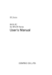
1.3 System Layout
Figure 1.1: System Layout of DNP-890
9
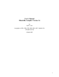
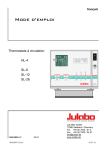
1.4 Indicators & Features
► Front View
► Rear View
10
► ByPass Pair View
11
Chapter 2
Preparation
12
2.1 Before You Begin
A stable and clean working environment are essential. Dust and dirt can get into components and cause a
malfunction. Use containers to keep small components separated.
Adequate lighting and proper tools can prevent you from accidentally damaging the internal components. Most
of the procedures that follow require only a few simple tools, including the following:
A Philips screwdriver
A flat-tipped screwdriver
A set of jewelers Screwdrivers
A grounding strap
An anti-static pad
Using your fingers can disconnect most of the connections. It is recommended that you do not use needle-nosed
pliers to disconnect connections as these can damage the soft metal or plastic parts of the connectors.
Before working on internal components, make sure that the power is off. Ground yourself before touching any
internal components, by touching a metal object. Static electricity can damage many of the electronic
components. Humid environment tend to have less static electricity than dry environments. A grounding strap is
warranted whenever danger of static electricity exists.
Computer components and electronic circuit boards can be damaged by discharges of static electricity. Working
on the computers that are still connected to a power supply can be extremely dangerous. Follow the guidelines
below to avoid damage to your computer or yourself:
Always disconnect the unit from the power outlet whenever you are working inside the case.
If possible, wear a grounded wrist strap when you are working inside the computer case. Alternatively,
discharge any static electricity by touching the bare metal chassis of the unit case, or the bare metal body
of any other grounded appliance.
Hold electronic circuit boards by the edges only. Never touch the components on the board unless it is
necessary to do so. Do not flex or stress the circuit board.
Leave all components inside the static-proof packaging that they shipped with until they are ready for
installation.
Use correct screws and do not over tighten screws.
13
2.3
This is the first step of all to proceed with, if you are to install a hard drive, CompactFlash Card, or memory
module.
Please remove one screw as indicated in
the right figure, prior to any moving of the
top cover. It is recommended to push the
top cover backwards so as to detach the
cover tongue out of the snatch-up at front
side, before the lift-up or removal of the
top cover.
Remove the four screws that hold the Hard
Drive bracket at the position, as indicated
in the right figure.
Once completed, the Hard Drive bracket is
ready for adding one 2.5” drive, and the
unit itself is ready for managing memory
module and Compact Flash.
Securing these screws are essential for
they would be re-used for the restoration
of the top cover, after all preparation
procedures are completed.
14
2.4 Accessing Memory
To install SO-DIMM
1. Open the top cover and locate the two memory slots, as in the red circle below.
2. Make sure the “Key” on Memory module and socket are perfectly matched, and add slowly the
memory modules into the socket along the plastic guides at both ends.
3. Make sure the Memory are snapped perfectly by the socket, and the two handles are restored back
to “close” position automatically. If not, press the handles to “close” position.
4. To remove the Memory module, please push the handles outwards, and the memory module will be
automatically disengaged.
15
2.5 Adding 2.5” SATA Hard Drive
It is to assume that no hard drive device has been installed within the system prior to undertaking this
procedure. However, in case a hard drive is in the system, this procedure demonstrates also a good illustration
as to how and where to start with attaching or replacing a hard drive.
Procedures:
(1) Acquire the Hard Drive bracket as addressed in the previous section of opening the top cover.
(2) As illustrated below, please have the 2.5” Hard Drive assembled with this bracket, assuring the Hard Drive I/O is
placed as indicated in the drawing below, and add in the suggested sequence below the four screws enclosed in
the accessory screw bag, for a perfect and firm Hard Drive subset.
(3) Restore this Hard Drive subset back to the chassis, to where and as how it was secured prior to being taken out,
and add the four screws back to position.
(4) A pair of SATA signal cable and SATA power cable are already half-assembled within the system and can be
found easily as the top cover is detached. Add these cables to SATA drive to complete the work.
16
2.6 Accessing CompactFlash Card
CompactFlash instead of CFast
As stated above, significant differences of CompactFlash and CFast are literally defined by their respective
interfaces, though the very resemblances can merely be indistinctly differentiated.
Alternative Substitute for SATA Drive
CompactFlash card runs on IDE interface, boasting a fascinating speed up to the kind as ATA133, while the true
bandwidth habitually depends on the firmware of CompactFlash card, producing comparably competitive
performance for most applications, were plenty of capacity adequately allocated for what is demanded by the
Operating Systems. It is not entirely degraded from SSD to any extent, by the outstanding stability as to the nospindle feature of itself. Such an interface is built internally for nothing but security reasons that can be
observed on most server platforms. Please open up the top cover to acquire access to this interface.
Procedures:
(1) Turn off the system, and remove the Hard Drive bracket.
(2) The onboard CompactFlash socket is to be accessed from the motherboard (as the red circle).
(3) Once add or replace a CompactFlash card, please add the top cover back. If a SATA Drive is not to be used in the
system at all, it is up to user’s decision as to whether to restore the Hard Drive bracket back to position or not.
Please be advised that CompactFlash card on IDE interface is never to be added or removed when the
system power is still turned on; that is, no plug-and-play scheme is enabled for this device. Disrespect of
such a limitation would very likely lead to system instability or malfunction, or even to the worst a fatal
system catastrophe. Please always turn off system power before accessing CompactFlash card.
17
Chapter 3
Operation
18
3.1 Turning On/Off The System
Please be advised that no VGA port is available with the system. A Console Connection with another PC for
visual confirmation is necessary, as usually achieved with VGA port.
Now add your cables, such as USB keyboard, USB mouse onto the USB ports (as with green circle at rear side),
as the merest devices to control the system. Leave the adaptor cable as the last cable to be added, right on
the DC-in Jack (as with blue circle at rear side).
Turn On the Power
In some cases, depending on whether a BIOS setting has been configured to allow immediate power-on upon
the delivery of AC power, system might come right up unexpectedly for no particular reason. Please refer to
BIOS section for details as to “Restore AC Power Loss”. Have you intended to bring it down, simply press once
the power switch (as with yellow circle at rear side), or press and hold for 4 seconds, to reach that goal.
However, in most occasions, without such abrupt event as stated above, simply press once on the Power
Switch to turn on the system.
Turn Off the Power
There are a few scenario where different approaches to turn off the system are recommended as below:
(1) Operating System: Regardless of the type of operating system in the hard drive, users should find no difficulty to
follow the standard power off procedure as is available within the said operating system. Modern operating systems
such as Microsoft® Windows® or Linux are usually designed with similar power scheme, where once initiated,
should bring the power down after a not so long and complicated shutdown process.
(2) BIOS: In case users intend to directly shutdown the system after a brief check within BIOS setup menu, simply press
once the power switch, or press and hold for 4 seconds, to achieve that goal.
(3) Software catastrophe: In the event that a software testing reaches a point of malfunction or endless loop, where no
restart or even user control is possible in software manner, it is suggested to simply press and hold the power
switch for 4 seconds to disengage the power.
Please never try to unplug the adaptor cable without trying the above approaches, as abruptly detaching the
adaptor cable while system power is still on might introduce unexpected power spikes or system inconsistency
due to data corruption and hence is the least suggested way to deploy.
19
Indication
ByPass LED
ByPass LED shall come lit constant ON when ByPass is enabled, regardless the system status at ON or OFF.
Power LED
Power LED shall come lit constant ON at system start.
Status LED
Power LED shall blink when system suspend mode is initiated.
HDD LED
Power LED shall blink in the wake of storage activity, such as SATA drive or CompactFlash.
First screen & Optimal BIOS Setting
Once the system successfully boots up, it shall activate display signal on monitor, disclosing some system
information as checkpoints for debugging, thereafter users are encouraged to bring up BIOS setup menu to at
least load the optimal BIOS setting, as the first thing to do at power on. Please refer to the BIOS section for
substantial details.
20
3.2 Installing Operating System & Drivers
Confirm the Hard Drive List
The system is designed to allow booting from a variety of internal devices, including USB pen drive, SATA
drive, and CompactFlash drive, etc. Given the tiny footprint and slow performance of USB pen drive, SATA
drive and CompactFlash are more prevailing devices to carry operating system and can to be found in the
detected drive list, in the section of IDE Configuration.
In the event that a particular SATA device is not detected and prompted in the device list, never would a
chance the system boot from it. Please turn off the system, check or re-apply the SATA cable and SATA power
cable, or re-insert CompactFlash card to ensure an appropriate connection.
Always Mind the SATA Mode
SATA controller is embedded in the Intel® J1900 Celeron Processor, and shall run only in one single SATA
mode at a time. Two different modes are available: IDE and AHCI. Please ensure that a SATA mode has been
selected for the installation, and always use this particular mode to boot the operating system being installed.
Failed to boot the operating system with the correct mode would definitely run into system collapse. While
thus disaster occurs, please re-select a SATA mode to try again the advisability of such change, so as to
determine the mode being used at installation phase.
Procedures to load operating system:
(1)
(2)
(3)
(4)
(5)
(6)
(7)
(8)
(9)
Please attach USB CD-ROM or DVD-ROM drive.
Start or restart the system.
Press “del” to go to BIOS setup menu.
Choose to confirm SATA Controller status. If it is enabled, select a SATA mode and go to (6).
If SATA Controller is disabled, bring it up and reboot to allow a re-detection of Hard Drives.
Confirm if the Hard Drive has been detected by the prompt of it on the drive list.
Scroll and choose to boot from optical device (CD-ROM or DVD-ROM).
Save and reboot the system to activate the change and start the installation.
Upon reception of messages or instruction from Operating System CD or DVD, please proceed with the rest of
the work as installer instructs.
Loading Extra Driver Files
Some challenges might occur during the installation, as if the issue of no Hard Drive detected, where extra
driver files are needed. This is mostly found, when AHCI mode is selected, in operating systems such as
Windows-XP, where a USB floppy drive loaded with SATA driver should be prepared and attached on USB port
and, at the prompt of such a message, please press “F6” key while being asked to do so, to allow the installer
integrate the driver file from floppy drive. Windows-7, or above, or most Linux OS (of the latest version)
apparently do not seem to come inherently with such an issue against the onboard SATA Controller, and
hence no extra driver would be needed.
On completion of the installation of operating system such as Microsoft Windows, please find the driver CD in
the enclosed accessory bag and proceed with driver files installation in the sequence as: INF (Chipset), VGA,
and LAN. If some driver updates are available by Windows Update, please mind the decision as to whether to
proceed with the update accordingly.
21
3.3 Understanding LAN Indicators
Activity LED
The left LED is LAN Port Activity LED, with three different indication status:
(1) Constant Yellow: Network is connected.
(2) Blinking Yellow: Network activity is on-going.
(3) Off: Network is not connected.
LAN Speed LED
The right LED is LAN Port Speed LED, with three different speeds:
(1) Amber: 1000 Speed
(2) Green: 100 Speed
(3) Off: 10 Speed.
Summary Table
LED
RJ45 NIC Linkage
(Left Side)
RJ45 NIC Mode
(Right Side)
Color
Yellow
Yellow
Off
Amber
Green
Off
State
On
Blinking
Off
On
On
Off
Description
LAN linked
LAN accessing
No LAN linked
Gigabit mode
100M mode
10M mode
3.4 Using Console Port
Please find the Console Cable in the enclosed accessory bag. Attach the RJ45 end at Console Port at front side,
and the other end of DB9 female end to the RS-232 Port of another notebook PC or Desktop Computer. Please
refer to the BIOS section for Console Setting, and mind the setting of Terminal Type as well as the Baud Rate
that would be configured for the Console activity. It is always recommended to use the same setting on the
system and also the Console PC to avoid nothing being transmitted or corrupted reception.
22
Chapter 4
BIOS Setup
23
About the BIOS
The BIOS (Basic Input and Output System) Setup program is a menu driven utility that enables you to make changes to
the system configuration and tailor your system to suit your individual work needs. It is a ROM-based configuration
utility that displays the system’s configuration status and provides you with a tool to set system parameters. These
parameters are stored in non-volatile battery-backed-up CMOS RAM that saves this information even when the power
is turned off. When the system is turned back on, the system is configured with the values stored in CMOS.
With easy-to-use pull down menus, you can configure such items as:
Hard drives, diskette drives, and peripherals
Video display type and display options
Password protection from unauthorized use
Power management features
When to Run BIOS
This program should be executed under the following conditions:
When changing the system configurations.
When a configuration error is detected by the system and you are prompted to make changes to the Setup
program.
When resetting the system clock.
When setting the CPU clock speed so that it automatically runs either fast or slow.
When redefining the communication ports to prevent any conflicts.
When making changes to the Power Management configuration.
When changing the password or making other changes to the security setup.
Normally, CMOS setup is needed when the system hardware is not consistent with the information contained in the
CMOS RAM, whenever the CMOS RAM loses power, or when the system features need to be changed.
When to Update BIOS
In the event that new features are released and a BIOS update is required, you will need to update your BIOS on
your own, with the help of an appropriate guide, a reference tool, and some command files for the job.
Please seek for help from your local dealer, or send your request to our technical support department.
24
4.1 Entering Setup
When the system is powered on, the BIOS will initiate the Power-On-Self-Test (POST) routines. These routines
perform various diagnostic checks. If an error is encountered, the error will be reported in one of two different ways:
If the error occurs before the display device is initialized, a series of beeps will be transmitted.
If the error occurs after the display device is initialized, the screen will display the error message.
Powering on the computer and immediately pressing <Del> allows you to enter Setup. Another way to enter Setup is
to power on the computer and wait for the following message during the POST:
TO ENTER SETUP BEFORE BOOT
PRESS <CTRL-ALT-ESC> OR <DEL> KEY
Press the <Del> key or press the <Ctrl>, <Alt>, and <Esc> keys to enter Setup.
4.2 Getting Help
The online description of the highlighted setup item is displayed at the right pane of the menu at all time.
Press F1 to pop up a small help window that lists all the function keys and its use.
To exit the Help Window, press <F1> or <Esc>.
4.3 Control Keys
The table below lists all the function keys for the navigation in the BIOS setup menu.
Function Key
Description
Up/Down Arrow Key
Move Up/Down
Left/Right Arrow Key
Move Left/Right
Enter Key
Select
+/- Key
Change value
ESC
Exit
Tab
Select a Field
F1
General Help
F2
Previous Values
F3
Optimized Values
F4
Save & Exit
To exit the Help Window, press <F1> or <Esc>.
25
4.4 The Main Menu
Figure 4-1: BIOS Setup Utility Main Menu
The menu bar on the top of the first screen has the following submenus:
Main: Basic system configuration.
Advanced: Advanced system settings.
Chipset: Other functions.
Security: Configure Supervisor and User Password
Boot: System boot configuration.
Save & Exit: Exit options as well as loading optimal defaults
System Time [xx:xx:xx]: Set the system time.
System Date [Day xx/xx/xxxx]: Set the system date.
26
4.5 The Advanced Menu
In this section, you may configure the followings: CPU Configuration, IDE Configuration, USB Configuration,
Hardware Monitor, Power Management, LAN Bypass Configuration, Serial Port Console Redirection, and SIO
Configuration.
27
CPU Configuration
Intel® Virtualization Technology
Enable/Disable Intel® Virtualization Technology.
EIST
Enable/Disable Enhanced Intel® SpeedStep® Technology for advanced power saving control against thermal
condition.
28
IDE Configuration
SATA Mode
Select a proper SATA mode from IDE and AHCI.
29
USB Configuration
Legacy USB Support
Enable this to allow using USB devices (Keyboard or Floppy) at some legacy operating systems, such as DOS. If
Auto is selected, USB Legacy Support will be disabled when no USB device is detected.
30
Hardware Monitor
CPU_Fan Smart Control
Enable/Disable CPU Fan Smart Control.
31
Power Management
Power Mode
Select AT/ATX Power Mode.
Restore AC Power Loss
This is to set the power state after an unexpected AC/power loss.
If [Power Off] is selected, the AC/power remains off when the power recovers.
If [Power On] is selected, the AC/power would come right on once power recovers.
If [Last State] is selected, the AC/power would follow the system state prior to the power loss.
32
Serial Port Console Redirection
Console Redirection
Enable/Disable Console Redirection function.
Console Redirection Settings
Enter to configure or confirm the Terminal Type and Baud Rate for Console activity.
Please be advised that Console Port is a function built over RS-232 COM Port. If users accidentally disable RS232 Port within SIO Configuration, Console Port will also be deactivated and hence no transmission will be
available.
33
SIO Configuration
Serial Port
Use This Device: Enable/Disable COM1
Possible: Configure the COM1 Setting (It is suggested to leave this setting unchanged as default)
PS2 Keyboard
Use This Device: Enable/Disable PS2 Keyboard.
Possible: Configure the PS2 Keyboard setting (It is suggested to leave this setting unchanged as default)
PS2 Mouse
Use This Device: Enable/Disable PS2 Mouse.
Possible: Configure the PS2 Mouse setting (It is suggested to leave this setting unchanged as default)
34
4.6 The Chipset Menu
35
North Bridge
Display Control Configuration
DVMT Pre-allocated: Select DVMT (Dynamic Video Memory Technology) Pre-Allocated Graphic Memory Size for
internal Intel(r) graphic device. Options: 64MB, 96MB, 128MB, 160MB, 192MB, 224MB, 256MB, 288MB,
320MB, 352MB, 384MB, 416MB, 448MB, 480MB, and 512MB.
DVMT Total Gfx Mem: Select DVMT (Dynamic Video Memory Technology) total Graphic Memory Size for
internal Intel(r) graphic device. Options: 128MB, 256MB, and Max.
36
South Bridge
Audio Controller
Enable/Disable onboard audio function.
USB 2.0 (EHCI) Support
Enable/Disable onboard USB 2.0 function.
37
4.7 The Security Menu
Administrator Password
Change Administrator Password
User Password
Change User Password
38
4.8 The Boot Menu
Quiet Boot
Enable: Display full screen boot up logo at start up.
Disable: Display POST message at start up.
OptionROM Message
Force BIOS: Display 3rd party ROM message at start up.
Keep Current: The 3rd party ROM message will be brought up only if the 3rd part manufacturer had set the add-on
device to do so.
Launch PXE OpROM
Enable/Disable Legacy Boot Option
Hard Drive BBS Priorities
Select which hard drive to boot first at system start.
39
4.9 The Save & Exit Menu
Save Changes and Reset
To save the changes and reboot the system.
Discard Changes and Reset
To reboot the system without saving the changes.
Restore Defaults
To load optimal default values from the BIOS ROM, select this field then press <Enter>. A dialog box will
appear. Confirm by selecting OK. You can also press <F9> to load optimal default values.
40
Chapter 5
WDT Programming Guide
41
Super I/O Register Table
Default Value
Index
0x2E
Data
0x2F
Note
SIO MB PnP Mode Index Register
0x2E or 0x4E
SIO MB PnP Mode Data Register
0x2F or 0x4F
WDT Register Table
LDN
Timer Counter
0x07
Register
0x73
BitNum
Value
Counting Unit
0x07
0x72
7
1
WDT Enable
0x07
0x72
6
1
TimeOut
0x07
0x71
0
1
Note
Time of watchdog timer (0~255)
This register is byte access
Select time unit.
1: second
0: minute
0: Disable
1: Enable
1: Clear timeout status
42
************************************************************************************
// SuperIO relative definition (Please reference to Table 1)
#define byte SIOIndex //This parameter is represented from Note1
#define byte SIOData //This parameter is represented from Note2
#define void IOWriteByte(byte IOPort, byte Value);
#define byte IOReadByte(byte IOPort);
// Watch Dog relative definition (Please reference to Table 2)
#define byte TimerLDN //This parameter is represented from Note3
#define byte TimerReg //This parameter is represented from Note4
#define byte TimerVal // This parameter is represented from Note24
#define byte UnitLDN //This parameter is represented from Note5
#define byte UnitReg //This parameter is represented from Note6
#define byte UnitBit //This parameter is represented from Note7
#define byte UnitVal //This parameter is represented from Note8
#define byte EnableLDN //This parameter is represented from Note9
#define byte EnableReg //This parameter is represented from Note10
#define byte EnableBit //This parameter is represented from Note11
#define byte EnableVal //This parameter is represented from Note12
#define byte StatusLDN // This parameter is represented from Note13
#define byte StatusReg // This parameter is represented from Note14
#define byte StatusBit // This parameter is represented from Note15
************************************************************************************
43
************************************************************************************
VOID Main(){
// Procedure : BestekWDTConfig
// (byte)Timer : Time of WDT timer.(0x00~0xFF)
// (boolean)Unit : Select time unit(0: second, 1: minute).
BestekWDTConfig();
// Procedure : BestekWDTEnable
// This procudure will enable the WDT counting.
BestekWDTEnable();
}
************************************************************************************
// Procedure : BestekWDTEnable
VOID BestekWDTEnable (){
WDTEnableDisable(EnableLDN, EnableReg, EnableBit, 1);
}
// Procedure : BestekWDTConfig
VOID BestekWDTConfig (){
// Disable WDT counting
WDTEnableDisable(EnableLDN, EnableReg, EnableBit, 0);
// Clear Watchdog Timeout Status
WDTClearTimeoutStatus();
// WDT relative parameter setting
WDTParameterSetting();
}
VOID WDTEnableDisable(byte LDN, byte Register, byte BitNum, byte Value){
SIOBitSet(LDN, Register, BitNum, Value);
}
VOID WDTParameterSetting(){
// Watchdog Timer counter setting
SIOByteSet(TimerLDN, TimerReg, TimerVal);
// WDT counting unit setting
SIOBitSet(UnitLDN, UnitReg, UnitBit, UnitVal);
}
VOID WDTClearTimeoutStatus(){
SIOBitSet(StatusLDN, StatusReg, StatusBit, 1);
}
************************************************************************************
44
************************************************************************************
VOID SIOEnterMBPnPMode(){
Switch(SIOIndex){
Case 0x2E:
IOWriteByte(SIOIndex, 0x87);
IOWriteByte(SIOIndex, 0x01);
IOWriteByte(SIOIndex, 0x55);
IOWriteByte(SIOIndex, 0x55);
Break;
Case 0x4E:
IOWriteByte(SIOIndex, 0x87);
IOWriteByte(SIOIndex, 0x01);
IOWriteByte(SIOIndex, 0x55);
IOWriteByte(SIOIndex, 0xAA);
Break;
}
}
VOID SIOExitMBPnPMode(){
IOWriteByte(SIOIndex, 0x02);
IOWriteByte(SIOData, 0x02);
}
VOID SIOSelectLDN(byte LDN){
IOWriteByte(SIOIndex, 0x07); // SIO LDN Register Offset = 0x07
IOWriteByte(SIOData, LDN);
}
************************************************************************************
45
************************************************************************************
VOID SIOBitSet(byte LDN, byte Register, byte BitNum, byte Value){
Byte TmpValue;
SIOEnterMBPnPMode();
SIOSelectLDN(byte LDN);
IOWriteByte(SIOIndex, Register);
TmpValue = IOReadByte(SIOData);
TmpValue &= ~(1 << BitNum);
TmpValue |= (Value << BitNum);
IOWriteByte(SIOData, TmpValue);
SIOExitMBPnPMode();
}
VOID SIOByteSet(byte LDN, byte Register, byte Value){
SIOEnterMBPnPMode();
SIOSelectLDN(LDN);
IOWriteByte(SIOIndex, Register);
IOWriteByte(SIOData, Value);
SIOExitMBPnPMode();
}
************************************************************************************
46
Chapter 6
Q & A
47
Q: The power switch is pressed, but nothing happens.
A: Please check the following before you call out for help:
(1) Loose adaptor cable => Push again.
(2) A bad or loose power switch => Push again.
Q: I can turn on the power, but the motherboard does not boot.
A: Please check the following before you call out for help:
(1)
(2)
(3)
(4)
Unevenly populated memory modules on the slots => Re-populate the memory module again.
CMOS checksum error => Clear CMOS or reseat the CMOS battery again.
Bad Hard Drive => Remove SATA signal cable or CompactFlash card and boot again.
Bad external devices => Detach RS-232 cable, LAN cable, and USB cable, and boot again.
Q: BIOS POST prompts but gets stuck.
A: Please check the following before you call out for help:
(1) CMOS checksum error due to Clear CMOS approach => Press F1 to bring up BIOS setup menu and load optimal setting.
(2) Bad Hard Drive => Remove SATA signal cable or CompactFlash card and boot again.
(3) Bad external devices => Detach RS-232 cable, LAN cable, and USB cable, and boot again.
Q: USB Keyboard does not work at DOS mode.
A: Please check the following before you call out for help:
(1) Check if USB keyboard is well plugged on USB port.
(2) Go to BIOS setup menu, Advanced/USB Configuration, and make sure Legacy USB Support is enabled.
Q: ByPass Relay does not flip
A: Please check the following before you call out for help:
(1) Shut down the system, restart and try again.
(2) Clear CMOS and try again.
Q: Nothing can be retrieved at Console Port
A: Please check the following before you call out for help:
(1) The default Console baud rate is 115200. Please configure this baud rate at the receiving side.
(2) Make sure RS-232 port and Console Redirection function are both enabled (at BIOS).
48
Q: System does not boot from USB CD-ROM/DVD-ROM
A: Please check the following before you call out for help:
(1)
(2)
(3)
(4)
USB CD-ROM/DVD-ROM is not plugged on USB port.
Check in the BIOS that CD-ROM/DVD-ROM has not been detected.
Check in the BIOS that CD-ROM/DVD-ROM has not been selected as the first boot device.
Unadvised misuse: Some OS installation CD/DVDs, such as Microsoft Windows, have a few seconds waiting time for
a keyboard press which triggers the system to boot from the CD-ROM/DVD-ROM. Otherwise, system would boot
from internal Hard Drive.
Q: System does not boot from USB Pen Drive
A: Please check the following before you call out for help:
(1)
(2)
(3)
(4)
USB Pen Drive is not well plugged on USB port.
Check in the BIOS that USB Pen Drive has not been detected.
Check in the BIOS that USB Pen Drive has not been selected as the first boot device.
Make sure your USB Pen Drive comes with a firmware designed for booting.
Q: Windows-XP installer does not find any Hard Drive
A: Please check the following before you call out for help:
(1) Check in the BIOS that SATA Hard Drive or CompactFlash has been detected.
(2) Check in the BIOS for correct SATA mode. If AHCI mode mode is selected, please refer to Chapter 3 to load extra driver
files.
Q: Windows does not boot straight forward, and keep rebooting itself or ends at a blue screen
A: Please check the following before you call out for help:
(1) Incorrect SATA mode => Change mode and boot again. In the case that you need to use a particular SATA mode which
was not used for the installation, you need to reinstall your Windows.
(2) A wrong image file has been used for cloning.
Q: Windows boots, but shuts down prior to showing graphic mode
A: Please check the following before you call out for help:
(1) Power switch stays at a pressed-down position => bring it up or move it off the header.
(2) Check if system fan is not rotating to the speed that is considered normal.
49
Q: My Windows does not shut down. It reboots in a few seconds after power off.
A: Please check the following before you call out for help:
(1) Press and hold the power switch for 4 seconds to see if your system shuts down permanently.
(2) Clear CMOS and try again.
Q: The display resolution is not right
A: Please change the resolution as follows (for Windows)
(1) Window-XP: Right-Click on the desktop and select Property for the configuration panel.
(2) Windows-7: Right-Click on the desktop and select Resolution for the configuration panel.
Q: I cannot connect my network with internet
A: Please check the following before you call out for help:
(1) Please consult your system administrator to confirm if a static network environment with security port designation
has been deployed. Otherwise, mostly, reassuring to have Windows acquiring IP address automatically would be
suggested and should resolve the situation. Please be referred to your system administrator for any further network
configuration setting. Window-XP: Right-Click on the desktop and select Property for the configuration panel.
(2) Please double check if ByPass function has been enabled.
Q: My Windows does not see more than 4GB RAM
A: A 32-bit operating system captures only 4GB memory.
Q: 4GB RAM is installed, but Windows only sees around 3.0GB capacity.
A: Some portion of the system memory will be allocated for system devices, especially the onboard video device.
Q: Some onboard devices are not detected in Windows
A: Please check the following before you call out for help:
(1) Please go to Device Manager to rescan these devices if necessary.
(2) If any of the LAN port is not detected (4 of them should be all detected), please go to BIOS setup menu, Advanced/PCIE
Ports Configuration, to see if any of them has been disabled.
Q: RS-232 Port does not work
A: Please check the following before you call out for help:
(1) Please go to Device Manager to see if COM1/COM2 are correctly prompted.
(2) Please go to BIOS setup menu, Advanced/Super IO Configuration, to make sure RS-232 port(s) has(have) been enabled.
(3) Please double check your RS-232 cable for correct pin definition.
50