1
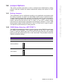
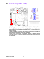
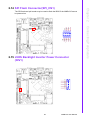
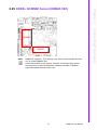
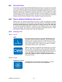
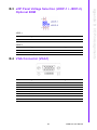
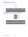
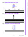
For computer cases equipped with ATX power supply, users should connect the
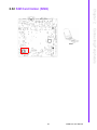
Power On/Off button on the computer case to (JFP1 + JFP2/PWR_SW) for convenient Power On/Off functionality.
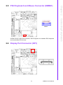
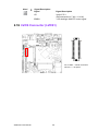
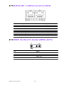
2.8.2 Reset (JFP1 + JFP2/RESET)
Many computer cases offer the convenience of a specific reset button. Connect the
wire for the reset button.
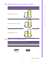
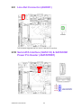
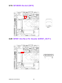
An LED can be linked to the connector (JFP2/HDDLED) to indicate when the HDD is
active.
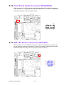
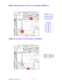
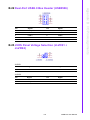
2.8.4 External Speaker (JFP1 + JFP2/SPEAKER)
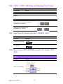
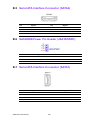
(JFP1 + JFP2/SPEAKER) is a four-pin connector for an external speaker. If no external speaker is available, the AIMB-215 provides an onboard buzzer as an alternative.
To enable the buzzer, set Pins 7-10 as closed.
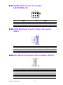
2.8.5 Power LED and Keyboard Lock Connector (JFP3/PWR_LED
and KEY LOCK)
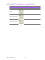
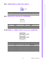
(JFP3/PWR_LED and KEY LOCK) is a five-pin connector for the Power-On LED and
Key Lock function. Refer to Appendix B for detailed information regarding the pin
assignments. The Power LED cable should be connected to Pins 1-3. The key lock
button cable should be connected to Pins 4 and 5.
Three power supply connection modes exist. The first is the ATX power mode, where
the system is powered on/off by momentarily pressing the power button. The second
is the AT power mode, where the system is powered on/off using the power supply
switch. The third is another AT power mode that involves the front panel power
switch. The status differences indicated by the power LED are listed in the following
table:
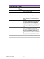
Table 2.2: ATX Power Supply LED Status (AT power not supported)
LED
(ATX power mode)
(On/off by
momentarily
pressing the power
button)
LED
(AT power mode)
(Powered on/off using
the power supply
switch)
LED
(AT power mode)
(Powered on/off
using the front panel
switch)
PSON1
(on the back plane) Pins 2-3 closed
jumper setting
Pins 1-2 closed
Connect Pins 1 and 2
to the panel switch
using a cable
System On
On
On
On
System Suspend
Fast flashes
Fast flashes
Fast flashes
System Off
Slow flashes
Off
Off
Power mode
21
AIMB-215 User Manual
Connecting Peripherals
2.8.3 HDD LED (JFP1 + JFP2/HDDLED)
Chapter 2
2.8.1 ATX Soft Power Switch (JFP1 + JFP2/PWR_SW)