1
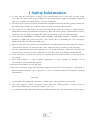
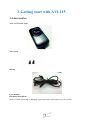
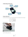
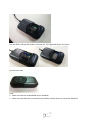
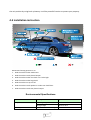
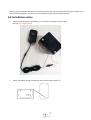
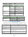
AVL-115 USER MANUAL
1
Table of Contents
1. Safety Information…………………………………………………….3
2. Main Function…………………………………………………………….6
3. Getting start with AVL115…………………………………………..7
3.1 Accessories ………………………………………………………..8
3.2 Identify component ……………………………………………8
3.3 Insert SIM card…………………………………………8
3.4 Setting APN……………………………………………..10
3.5 LED Signal Definitions………………………………10
4. Operation………………………………………………………………….11
4.1 SMS Command list…………………………………………...11
4.2 Security alarm system……………………………………….12
4.3 Installation instruction………………………………….….12
4.4 Installation notice …………………………………………….13
5. Specification……………………………………………………………….
6. Fault and Solution……………………………………..………………14
2
1. Safety Information
2. As this unit has the ability to track, users should make use of this unit in legal right.
Users have to take all t he responsibilities if invading others’ rights by illegall y using this
unit, for example: invading others’ secrets on purpose.
3. This unit gets relative position infor mation t hrough Global Positioning s ystem ( GPS). By
the limitation of GPS, it is nor mal if the posi tion is drifted and uns table.
4. The accuracy of GPS mobile position and global positioning s ys tem is maintained by
DOD(United States Depart ment of Defense). Base on public policy and national security,
USA reser ves the ri ght to change the GPS s ystem and precision wit hout warning.
5. This unit has GSMMHZ, 850/900/1800/1900MHz and GPRS module, Customer should
purchase a SIM card f rom local store. The s ervice has to including the voice message,
SMS and is able to cancel the SIM code.
6. Before using this unit, please log on platfor m, click the operation guide and please follow
“Quick Start Guide” t o confi gure the setup. Then the unit is ready to start wor king.
7. Do not dis mount the antenna randoml y, or use other antennas. This may interfere the
trans mission, and increase the radiation as well. This may will damage human health.
8. After switch on, you can set anyti me to trans mit position infor mation to ser vice platfor m
for search.
9. This unit belongs to high frequent equipment. It may explode or damage in the
environment with flammable liquids.
10. Do not disassemble or refit the unit
11. Services should be requested if damage happens to this unit. For examples, any liquid or
dust contaminating this unit, exposure to r ain or extreme humid environment, wor kin g
abnor malit y
Warning
1. If customers dissembl e the machine by themselves, the guarantee will invalid.
2. The unit requires stable receptions from GPS and GSM s ystems. It may result in
positioning difficulty if reception signal is too low.
3. It is nor mal to hear the sound when you shake the unit because contain the motion sense.
3
2. Main Function
1. Location and tracking: Getting address by SMS or GPRS or getting more information through
internet.
2. SMS: address and status feedback in multiple languages
3. Individual tracking software (free of charge):
Real-time
Multiple views
History tracking
Geo fence,
Speeding alert
4. Internal antenna
5. Back up battery in case thief cut cable line
6. LBS (location based service), GPS, and GSM mobile networks position
7. Multiple user management (admin, user, and more)
8. The AVL115 is Global Quad-Band GSM 850/900/1800/1900 Mhz and GPRS TCP/UDP
9. Send e-mail or SMS when alarm
10. Used map: Google map
11. Auto tracking: Setup the intervals you want the tracker report to you.
12. Movement Alert: Send SMS to the unit to start the movement alert function. When the vehicle is
moving, the unit will send the movement alert to the authorized numbers.
13. Supports multiple languages(English, Simple Chinese, Traditional Chinese, Spanish, Turkish)
4
3. Getting start with AVL115
3-1Accessories
AVL 115 Tracker body
Two Screw
Wiring
User manual
Hardware description
Notice: If item is missing or damaged, repack the tracker and return it to your reseller.
5
3-2Identifying Components
GPS LED
GSM LED
Power LED
Setting Port
Power Cable
3-3Insert SIM card
Insert SIM as following, open the cover, and put the SIM card into the holder and turn the foil right.
Open the rear cover
Push the foil along and turn it up.
6
Put the SIM card into the holder, and turn the foil right and fasten it in place.
Put the cover back
Note:
1. Make sure that the installed SIM card is workable.
2. Make sure that SIM card is cancelled.(Install SIM to mobile phone to cancel the SIM lock)
7
3-4 Setting APN
Using your mobile phone to set the APN, firstly, send SMS 510#0000#Internet to the unit number.
(0000 is your default password, internet is your local APN, APN is different in different area, for
example, APN in USA is epc.tmobile.com and therefore, user has to check your APN first from your
operator)
If APN is epc.tmobile.com and the setting is successful, the unit will send response “SETUP OK:
APN= epc.tmobile.com IP=59.120.198.206 PORT=6868”
(See more operation in 5-1)
3-5LED Signal Definitions
Indication
Conditions
LED display
Service
Limit service (no sim card in)
Red LED On
( Power)
Blue LED On
( GPS )
Orange LED On
Mode
( GPRS)
No GPRS service (no signal)
Orange LED on
GPS Not Fixed
Blue LED On
GPS Not Fixed
Blue LED On
GPS Fixed
Blue LED blinking
GPRS Not connection
Orange LED on
GPRS connection
Orange LED blinking
Working
Red LED On
8
4. Operation
4-1SMS Command list
To locate the GPS tracker position, if require anytime.
A:SMS: Send 720#0000 in SMS to unit to locate tracker position.
(0000 is password currently, please change in the platform.)
B: Voice Surveillance
Direct to locate SIM card position by phone, dial the tracker phone number and hang up after two
beep, the SMS will automatically be sent to the user to inform the location of the tracker.(Warning:
Remember to set SIM card display ID function)
SMS
Command
Example
Response
Description
001
001#0000
AVL115B101019Bestwe
Acquire Version
111
111#0000
Current address
SMS response address
410
410#0000
IMEI = 355543020119954
Response the number of IMEI
510
510#0000#cmnet
SETUP OK: APN=cmnet
Setting APN/IP/Port
IP=59.120.198.206
PORT=6868
520
520#0000
APN=cmnet
IP=59.120.198.206
Setting APN/IP/Port
PORT=6868
720
720#0000
PARK OFF !
Unlock Park security alarm
721
721#0000
PARK ON !
Setting Park security alarm
937
937#0000#0
Engine OFF !
Cut off Engine (Oil)
937
937#0000#1
Engine ON !
Release
Park Alarm
Tracker automatic send
Park alarm: Current address
After setting Park alarm. It will
send SMS to host if car move.
Car power off Tracker automatic send
Car Power Off: current
address
If main power be cut, it will
change to use back up battery.
Call Tracker & Tracker automatic send
hand up
Current address
SMS response address
4-2 Security alarm system
If tracker has been cut main power by thief, it will send SMS to inform customer and continue track
9
the unit position by using back up battery. It will be powerful function to protect your property.
4-3 Installation instruction
Recommend setting position in car
1. Hide the tracker under windscreen.
2. Hide the tracker inside plastic bumper
3. Hide the tracker under rear dash or 3rd brake light
4. Hide the tracker under bug shield
5. Hide the tracker on top of roof
6. Hide the tracker inside speaker or under rear dash fabric
7. Hide the tracker inside rear plastic bumper
Environmental Specifications
Item
Description
Specification
Temperature
Operating range
-10 °C to 55 °C
Storage range
-20 °C to 70 °C
Humidity
up to 95% non-condensing
10
Warning: If the windshield affixed to the metal Sun Control Film ,this will reduce the GPS signal reception and
cause malfunctioning GPS. Therefore, we recommend to replace the installation location.
4-4 Installation notice
1.
Connect with 12V battery. Remember to set positive and negative level on right
way.(Block is negative level)
2.
Please remember setting as following; turn the back battery power on.
11
3.
CUT off Engin (Oil)
5. Specification
GPS Specifications
Item
Description
Specification
Chipset
Skytraq
Venus638LPx
Sensitivity
Tracking
-161dBm
General
Frequency
L1, 1575.42 MHz
C/A code
1.023 MHz chip rate
Channels
51 Channel Acquisitions
14 Channel Tracking
Datum
Default
WGS-84
Accuracy
Position
2.5m CEP
Velocity
0.1 meters/second
Time
300ns
Time to First Fix (TTFF)
Reacquisition
0.1 sec., average
Open Sky & Stationary
Hot start
1 sec., average typical TTFF @ -130dBm
Requirements
Warm start
28 sec., average typical TTFF@
-130dBm
Cold start
29 sec., average typical TTFF@
-130dBm
12
Dynamic Conditions
Acceleration
4g, max.
GSM/GPRS Specifications
Item
Description
specification
Air Interface
GSM or GPRS Quad
850/900/1800/1900MHz
Band
Support Class 12 GPRS
Protocol Stack
GSM Rel.97. STK Rel.99
GPRS Rel4.0 Class 10
Output Power
Class 4 (2W) at 850/900 MHz
Class 1 (1W) at 1800/1900 MHz
GSM Sensitivity
Messaging
850/900 MHz
-108 dBm
1800/1900 MHz
-107 dBm
SMS concatenated
Yes
Smart
Yes
messaging(GPRS)
Electrical Specifications
Item
Description
Specification
Supply voltage
From Car Power
9 V – 40V
Power consumption
Operation mode (GSM)
130mA~ 270mA
Standby mode (Trace On)
70±5mA
Power saving mode (Trace Off)
7mA
6. Fault and solution
The Chart below shows the possible unusual conditions and methods to solve the problems; you may
try solving the problem according to the suggested instructions before consulting the service engineer.
Fault
Solution
The tracker is not able to be
activated.
Please check if the SIM Lock is cancelled.
All the three LED are on after
turning on the device.
Please check if the SIM card is installed properly.
Fail to receive the SMS report from Dial the SIM number to check if this SIM is workable or not.
the tracker.
Check with the provider if this SIM runs out of credit or does not
open the SMS function.
The GPRS is unable to upload the
coordinates.
Make sure the APN and IP/Port settings are correct.
There is screw-like noise while
The tracker is built-in with a sensor ball and it is normal to hear the
13
shaking the tracker.
noise while the sensor ball is moving.
7. Certification and Safety
Approvals/General Information Caution
Important information regarding safe and efficient operation: Read this information before using the
product. Users are not permitted to make changes or modify the device in any way. Any changes or
modifications not expressly approved by the party responsible for compliance could void the user’s
authority to operate the equipment.
Disclaimer
The information in this document is subject to change without notice. The manufacturer makes no
representations or warranties with respect to the contents hereof and specifically disclaim any
implied warranties of merchantability or fitness for any particular purpose. The manufacturer
reserves the right to revise this publication and to make changes from time to time in the content
hereof without obligation of the manufacturer to notify any person of such revision or changes.
Operation is subject to the following two conditions:
This device may not cause interference and 2) this device must accept any interference, including
interference that may cause undesired operation of the device.
Europe–EU Declaration of Conformity
This device complies with the specifications EN301489, EN55022, EN55024, EN300440, EN301511,
EN60950_1, EN50360 and EN62209_1 following the provisions of the R&TTE Directive
14