1
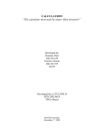
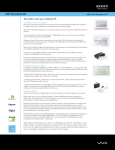
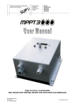
 2x4 DVI Matrix AS‐2124 User Manual Introduction
The AS‐2124 allows you to switch between two DVI sources and four DVI displays independently with compact pattern generator functionality. Any input can be switched into any output through a remote control. To simplify the switching process, AS‐2124 comes with an IR remote control. If you don’t have an IR remote control nearby, AS‐2124 can also be configured by two DIP switches (one rotary switch and one DIP switch). Furthermore, the AS‐2124 is designed to regenerates every signal carried to itself so that every signal sent out from the AS‐2124 is as crystal clear as the original. DVD Player A DVI Matrix DVD Player B 2
Features
z
Pixel Rate up to 165MHz.
z
z
Maintains highest resolution digital video with no loss of quality
Configured by IR remote control with OSD display.
z
Embedded Pattern Generator.
z
Supports EDID learning. The AS-2124 can get the EDID information for the
z
output device and pass it to the input equipment.
DIP switch configuration. Without IR remote control, the switcher can also be
configured by the DIP switch and the rotary switch.
z
Can be cascaded more than two tiers. The signal carried to the AS-2124 will be
z
decoded and encoded.
Compact size.
Package Contents
1. 1x AS-2124
2. 1x IR remote control
3. 3x DVI Y-cable
4. 1x User Manual
5. 1x 5V DC power adapter
Technical Specifications
z
Video Amplifier Bandwidth: 1.65 Gbps
z
Input Video Signal: 1.2 volts p-p
z Input DDC Signal: 5 volts p-p (TTL)
z
Single Link Range: 1080p/1920 x 1200
z
DVI Connector: DVI-I 29 pin female (digital only)
z
Power Supply: 5 VDC
z Power Consumption: 10 watts (max)
z
Dimensions: 130mm/5.1”x 110mm/4.3”x 25mm/1”(Lx Wx H)
z
Weight: 340g/12oz
Remote Control
3
z
Figure below shows the remote control of the AS-2124. Only four arrow buttons
and the menu button works. The remaining buttons are reserved and no use for
this product.
z
Press “Menu” to launch OSD menu and use arrow buttons to move around the
items in the OSD menu. Right arrow button allows you to confirm your selection.
Press “Menu” again to exit the OSD menu.
Panel Descriptions
Front View
1
1.
2.
2
Please plug in one DVI Y-cable here and connect 1 and 2nd DVI monitor.
Please plug in one DVI Y-cable here and connect 3rd and 4th DVI monitor.
st
Rear Panel
4
3
4
5
6
7
8
3.
5V DC power jack
4.
Plug in one DVI Y-cable here and connect 1st and 2nd DVI sources.
5.
6.
Rotary switch. For detailed setup, please see the next section.
LED indicator (EDID)
7.
Power indicator
8.
IR receiver
DIP Switch
When the remote control is not available, the switcher can also be configured by DIP
switch shown as the following:
Fig.1
Fig.2
*Please always set DIP Switch 1 at ON.
*When you need to configure the device by DIP Switch, Set DIP Switch 2 at ON. Set DIP
Switch at OFF only when you need to control the device by remote control.
Dip Switch
3 On
3 Off
4 On
Output 4
Output 3
4 Off
Output 2
Output 1
Table 1
5
DVI Output1
Rotary Switch
DVIFunction
Output2
0
Source 1
1
Source 2
2
Pattern 1
3
Pattern 2
4
Reserved, no use
5
Pattern 4
6
Pattern 5
7
Reserved, no use
Table 2
Fig.1 shows a DIP switch from which you can select a specific output. Fig.2 shows a
rotary switch that allows you to select an input source or a test pattern. The two switches
should be configured at the same time. For example, if you want to set 1st display to show
source 1, please follow the steps. Firstly, see table 1 and set DIP switch at 3 off and 4 off
position (output 1). Secondly, turn rotary switch to 0 (source 1).
Hardware Installation
1. Plug in a DVI Y-cable to DVI Input.
2. Plug in a DVI Y-cable to DVI Output1 and a Y-cable to DVI Output 2.
3. Connect source 1 and source 2 to the Y-cable that plugged in DVI Input.
4. Connect display 1 and display 2 to the Y-cable that plugged in DVI Output 1.
5. Connect display 3 and display 4 to the Y-cable that plugged in DVI Output 2.
DVI Source1
DVI Source2
DVI Input
6
Display1
Display2
Display3
Display4
All I/O configurations can be readily set up by the remote control through an OSD
menu. Below shows the OSD menu tree:
Port
Source
RED
Port 3
Port 2
GREEN
Source
Power Off
BLACK
WHITE
7
Port 4
Monitor Test
LINE
DOT
MOIRE
MOIRE
Press “Menu” on the remote control and then the OSD menu pops up as below,
GOMAX ELECTRONICS
Port 1
Port 2
Port 3
Port 4
In this page, you can select any output port you want to configure. After you press
the up/down arrow button on the remote control to select a specific port, the menu will
automatically be changed to the next page shown as below:
GOMAX ELECTRONICS
Source 1
Source 2
Power Off
Monitor Test
In this page, you can select the video source you want to send to the port selected.
The input DVI connector can connect to 2 different video sources and shown as Source 1
and Source 2. If you want to save power, you can turn off the chip by selecting “Power
Off.” Then, the port will turn to the idle mode. The “Monitor Test” function triggers the
embedded pattern generator. It can help to check dead/lazy pixel and some LCD status.
8
When the Monitor Test item is selected, it will turn to the next OSD table shown as the
following:
ASCALE Enterprise
RED
GREEN
BLUE
BLACK
WHITE
LINE MOIRE
DOT MOIRE
In the pattern menu, each item stands for a pattern. For example, the first five patterns
show a single color to help check dead pixels.
9
Limited Warranty
Ascale warrants the AS-2124 2x4 DVI Matrix to be free from defects in the material
and workmanship for 1 year from the date of purchase from Ascale or an authorized
dealer. Should this product fail to be in good working order within 1 year warranty period,
Ascale, at its option, repair or replace the unit, provided that the unit has not been
subjected to accident, disaster, abuse or any unauthorized modifications including static
discharge and power surges.
Unit that fails under conditions other than those covered will be repaired at the
current price of parts and labor in effect at the time of repair. Such repairs are warranted
for 90 days from the day of reshipment to the buyer. If the unit is delivered by mail,
customers agree to insure the unit or assume the risk of loss or damage in transit. Under
no circumstances will a unit be accepted without a return authorization number.
The warranty is in lieu of all other warranties expressed or implied, including without
limitations, any other implied warranty or fitness or merchantability for any particular
purpose, all of which are expressly disclaimed.
Proof of sale may be required in order to claim warranty. Customers outside Taiwan
are responsible for shipping charges to and from Ascale. Cables are limited to a 30 day
warranty and cable must be free from any markings, scratches, and neatly coiled.
The content of this manual has been carefully checked and is believed to be
accurate. However, Ascale assumes no responsibility for any inaccuracies that may be
contained in this manual. Ascale will NOT be liable for direct, indirect, incidental, special,
or consequential damages resulting from any defect or omission in this manual, even if
advised of the possibility of such damages. Also, the technical information contained
herein regarding the ASCALE-2124 features and specifications is subject to change
without further notice.
Remote Control
10