1
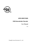
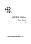
JXDH-6303 4 in 1 QAM Modulator
User Manual
Chengdu Jiexun Electronics Co., Ltd.
Chapter 1
Product Outline
1.1 Outline
JXDH-6303 4 in1 QAM Modulator is a high performance device researched by
Chengdu Jiexun Electronics Co., Ltd., integrate 4 routes QAM modulating carrier
outputs, support 4 ASI inputs or DVB-S/DVB-S2/DVB-T standard RF
input(selectable built-in tuner), after 4 separated encoding and modulating, then
RF out directly in high performance.
Support local and remote control to adjust the device parameter, equal to 4
individual QAM modulators, so cost and space saved.
1.2 Features
•
•
•
•
•
•
•
•
•
•
•
•
Fully support EN300 429/ITU-T J.83A
4 neighbor frequency QAM modulating carrier Output
4 ASI inputs, support 188/204 byte TS package
Support DVB-S/DVB-S2/DVB-T RF Input (optional)
Support PCR accurately correct
Constellation: 16QAM、32QAM、64QAM、128QAM、256QAM
Symbol Rate: 4.0Mbauds~7.0Mbauds
Support NIT insert, update
RF output frequency: 48MHz~860MHz,
RF output Level: -20dBm~0dBm,stepping at 0.5dB step
LCD display panel to operate
Support network management (NMS)
Application Scope
MMDS digital TV headend;
Satellite digital TV broadcasting;
Terrestrial digital TV;
Image monitoring;
Video on Demand (VOD);
Remote education;
1
TV conference.
1.3 Performance Index
Input
Modulate
Specification
RF Output
System
4 routes ASI inputs, BNC interface;
DVB-S/DVB-S2/DVB- T RF input (optional)
QAM route amount
4
Modulate standard
EN300 429/ITU-T J.83A
Symbol rate
4.0~7.0Mbauds,stepping at
1kbps
Constellation
16、32、64、128、256QAM
FEC
RS(204, 188)
Connector
F, 75Ωimpedance
Frequency range
48MHz~860MHz
Output level
-20dBm~0dBm(per carrier),
stepping at 0.5dB
MER
≥ 40dB
ACLR(Adjacent Channel
Leakage Ratio)
-60 dBc
Support LCD panel operation, network management, Chinese
and English operation interface.
Remote control to adjust parameter and update by internet.
General
Measurement(L×W×H)
482mm×300mm×44.mm
Weight
3.2kg
Temperature range
0~45℃(work),
-20~80℃(store)
Power requirement
AC 110~220V ±10%, 50/60Hz
Power consumption
≤50W
1.4 Appearance and Description
Front Panel Illustration
2
QAM Modulator
Power
1
Alarm
CH1 TS Lock
Over flow
CH2 TS Lock
Over flow
CH3 TS Lock
Over flow
CH4 TS Lock
Over flow
2
3
4
Digital
Enter Menu
Video
Broadcasti
5
7
6
8
1: LCD display screen
2: Power indicator
3: Channel 1,2,3,4, code stream signal indicators (code steam signal input, the
green indicator light)
4: Alarm indicator
5: Channel 1,2,3,4, code stream signal overflow indicators (code steam signal
overflow, the red indicator light)
6: Up /Down/Left/Right buttons
7: Enter button
8: Menu button
Rear Panel Illustration
ETHERNET
ASI IN 1
ASI IN 2
ASI IN 3
ASI IN 4
RF OUT
AC100V-220/50/60Hz
TEST
0
1
1
2
3
4
5
1: Ethernet interface;
2: 1st Channel ASI input;
3: 2nd Channel ASI input;
4: 3rd Channel ASI input;
5: 4th Channel ASI input;
6: RF OUT output;
7: RF TEST output;
8: Power switch;
9: Fuse;
3
6
7
8
9
10
11
10: Power Socket;
11: Grounding;
Chapter 2 Installation Guide
2.1 Acquisition Check
When users open the package of the device, it is necessary to check items
according to packing list. Normally it should include the following items:
• 4-in-1 QAM Modulator
1
• User’s Manual
1
• Q9 head end coaxial cable
4
• AC Input Power Cord
1
If any item missed or mismatch with the above list, please contact company at
once.
2.2 Installation Preparation
When users install the device, please follow the below steps. The details of
installation will be described at the rest part of this chapter. Users can also refer
rear panel chart during the installation.
The main content of this chapter including:
z
Checking the device missed or damage during the transportation
z
Preparing relevant environment for installation
z
z
Installing 4-in-1 QAM Modulator
Connecting signal wires
2.2.1 Device’s Installation Flow Chart Illustrated as following
Acquisition
Check
Fixing
Device
Connecting
Grouding
Wire and
Power
Cord
Connecting
Signal Wire
4
Setting
Parameter
Running
Device
2.2.2 Environment Requirement
Item
Requirement
Machine hall space
When user install machine frame array in one machine hall, the
distance between 2 row of machine frames should be 1.2~1.5m
and the distance to wall should be no less than 0.8m。
Machine hall floor
Electric Isolation, Dust Free
Volume resistivity of ground anti-static material: 1×10⁷~1×10¹⁰Ω;
Grounding current limiting resistance: 1MΩ
Floor bearing should be greater than 450Kg/m2
Environment
temperature
5~40°C sustainable ,0~45°C short time,
installing air-conditioning is recommended
Relative temperature
20%~80% sustainable 10%~90% short time
Pressure
86~105KPa。
Door & window
Installing rubber strip for sealing door-gaps and dual level glasses
for window
Wall
It can be covered with wallpaper, or brightness less paint.
Fire protection
Fire alarm system and extinguisher
Power
Requiring device power, air-conditioning power and lighting
power are independent to each other. Device power requires AC
power 110V/220V 50Hz. Please carefully check before running.
2.2.3 Grounding Requirement
•
•
•
•
All function modules’ good grounding designs are the base of reliability and
stability of device. Also, they are the most important guarantee of lightning
arresting and interference rejection. Therefore, system must follow these rules.
Coaxial cable’s outer conductor and isolation layer should keep sound electric
conducting with the metal housing of device.
Grounding conductor must adopt copper conductor in order to reduce high
frequency impedance, and the grounding wire must be as thick and short as
possible.
The ends of terminal grounding wire must make sure for well electric
conducting, and process for antirust.
•
It is prohibited that users use other devices as part of grounding wire’s electric
circuit
5
z
The section of the conjunction between grounding wire and device’s frame
should be equal or greater than 25mm2
2.2.4 Frame Grounding
All the machine frames should connect to protective copper strip. The grounding
wire should be as short as possible and avoid circling. The section of the
conjunction between grounding wire and grounding strip should be equal or
greater than 25mm2
2.2.5 Device Grounding
Connecting the device’s grounding rod to frame’s grounding strip with copper
wire.
2.3 Wire’s Connection
The power supply outlet is located at the left of rear panel, and the power switch is
just above it. The protective grounding wire connective screw is located at the
down-left side of power supply outlet
• Connecting Power Cord
User can insert one end into power supply outlet, while insert the other end to AC
power.
• Connecting Grounding Wire
When the device solely connects to protective ground, it should adopt independent
way, say, share the same ground with other devices. When the device adopts
united way, the grounding resistance should be smaller than 1Ω
)Caution:
Before connecting power cord to 4 in 1 QAM Modulator, user should set the power
switch to “OFF”. And require the same grounding with the power system
2.4 Signal Wire Connection
6
The signal connections including the input signal wire and output signal wire. The
input signal wire connects with the 4-in-1 QAM Modulator by the head end Q9
coaxial cable; 4-in-1 QAM modulator outputs are divided into a main output, one
monitor output.
ASI input wire illustration:
2.4.1 ASI Input Connection
User can find ASI input wire, according to connector marks described in the rear
panel illustration and diagram of the device’s description, and then, connecting the
ASI input interface, one end connected to ASI input interfaces of the 4-in-1 QAM
modulator, and the other end connected to ASI output interfaces of each code
steam Multiplexer or Scrambler;
4 in 1 QAM Modulator ASI input interface wire connection diagram is following:
Chapter 3 Operation
4 in 1 QAM modulator, the front panel is user operation interface. Before users
start their business, they can decide whether directly use the factory setting, or
customize the parameter setting.
Two ways can set the 4-in-1 QAM modulator parameter;
One is using the buttons on the front panel to set the parameter with the assistance
7
of the LCD display screen.
The other way is making use of the device’s Network management software.
Setting the parameter through computer network management interface by local or
remote control
4 in 1 QAM modulator menu items include:
1. system parameter.
2. channel setting.
3. local setting.
4. factory default.
5. language select.
6. Version
3.1 Front Panel Keyboard Function Description
ENTER: Activating the LCD panel, and select the parameters which need to
modify, then confirming the changes after modification;
UP、DOWN、LEFT、RIGHT: Selecting parameter needing to be modified,
Modifying activated parameters or paging Up/Down when parameter is
inactivated.
“Menu” button: Menu; return; exit
Stop operation after 2 minutes,
Automatically returns to the boot menu screen, and waiting for activation.
3.2 The 4 in 1 QAM modulator device parameter setting
3.2.1 Initialization
After finishing installation according to the former introduction, open power,
meanwhile, the green power indicator on front panel works.
The LCD may show the 3 displays.
Display1
1. Frequency:800 MHz
3. Frequency:816 MHz
8
2. Frequency:808 MHz
4. Frequency:824 MHz
Display2
1.Rate: 30.000Mbps
3.Rate: 32.000Mbps
2. Rate: 00.000Mbps
4. Rate: 00.000Mbps
1. ASI input lock !
3. ASI input lock!
Or Display3
2. ASI
4. ASI
input loss !
input loss !
If display3 showing:
Please check the corresponding input port and signal cable connection is working!
3.2.2 Enter 4-in-1QAM modulator main menu
When enter the main menu, press on the front pane “enter” button, then you can
access the main menu of the device. (just show 1-4 items each display screen)
LCD screen displays the following:
1. System parameter 2. Channel setting
3. Local setting
4. Factory default
Press on
(Down) button of the front panel to enter the next page, the LCD
screen displays as following:
5.
Language select
6.
Version
Remarks: The main menu has 6 sub-menus:
1. system parameter; 2.channel setting; 3.local setting;
4. factory default; 5.language select; 6. Version
3.2.3 Enter device system parameter sub-menu
After you press the “enter” button to access the main menu, the LCD screen
9
display:
You can see
(movable cursor) at the front of “1. System parameter” showing on
the LCD screen, then press “Enter” button to enter the sub-menu “System
parameter”. (You can use Up/Down/Left/Right buttons to select the sub-menu
which you wanted, and then press “Enter” button to access the required sub-menu)
The LCD screen displays as following:
1.1
1.3
Start frequency
Symbol rate
1.5
Attenuation
1.2
1.4
Constellation
Bandwidth
1.1 The initial frequency setting of device (After the three frequency followed by
the initial increase in frequency 6MHz or 8MHz automatic configuration); 1.2
16-256QAM modulation mode; 1.3 Symbol rate settings(4-7Mbauds); 1.4 Output
frequency bandwidth of the device selection(6MHz or 8MHz); 1.5 Device output
level attenuation (0.5dB step)
When access the sub-menu of the system setting, use the Up/Down/Left/Right
buttons, move the cursor to the sub-menu which you need. And then press “Enter”
button to access. Next, still use the Up/Down/Left/Right buttons to move and
modify the parameters. And press “Enter” button to confirm the changes
3.2.4 Enter channel setting sub-menu
After access the main menu, you can see
the cursor at the front of “1.System
parameter” on the LCD screen. Press “Right” button to move the cursor to the
front of “2. Channel setting”, And press “Enter” button to access the Channel
setting sub-menu.(You can use Up/Down/Left/Right buttons to move the cursor to
the front of the sub menu which you need, and press “Enter” button to confirm)
The LCD screen displays as follow:
2.1 Ch 1 setting
2.3 Ch 3 setting
2.2 Ch 2 setting
2.4 Ch 4 setting
10
(2.1 first channel; 2.2 Second channel; 2.3 Third channel; 2.4 Forth channel)
Then you can see the cursor staying at 2.1, press “Enter” button to access “ch 1
setting” sub-menu.
Then the LCD screen displays is following:
2.1.1 Output carrier
2.1.3 NIT Insert
2.1.2 Attenuation
(2.1.1 The first channel carrier output switch; 2.1.2 The first channel level
attenuation setting (0.5db step); 2.1.3 The first channel NIT insert)
After access the “ch l setting” menu, use the Up/Down/Left/Right buttons move
the cursor to the front of the sub-menu which you want. And then press the
“Enter” button to access. Next also use the Up/Down/Left/Right buttons to move
and modify the parameters. After finish the setting, press “Enter” button to
confirm the changes.
The other 3 channels can be settled with reference of the above operations.
3.2.5 Enter local setting sub-menu
After access the main menu, you can see the
cursor at the front of “1.system
parameter” showing on the LCD screen. Press “Down” button to move the cursor
to the front of “3. local setting”, then press “Enter” button to access the “local
setting” sub-menu.
The LCD screen displays:
3.1 IP address
3.3 Subnet mask
3.2 Gateway address
3.4 Physical address
(3.1 IP address setting; 3.2 Gateway address setting;3.3 Subnet mask setting; 3.4
Physical address setting)
After access the Local setting sub-menu, press Up/Down/Left/Right buttons to
11
move the cursor at the front of the sub-menu which you need, then press “Enter”
button to access. And also press Up/Down/Left/Right buttons to move the cursor
and modify the parameters. When setting complete, press “Enter” button to
confirm the changes.
3.2.6 Enter factory default sub-menu
After access the menu, you can see the
cursor at the front of “1.system
parameter” on the LCD screen. Press “Right” button to move the cursor to the
front of “4.Factory default”, then press “Enter” button to access the “factory
default” sub-menu.
The LCD screen displays:
4.1 Load default setting
YES
*NO
Then, use the “Enter” button to select “YES” or “NO”
Choose the “YES” and press “Enter” button again, the parameter default setting
will be done and saved soon. And return to the menu automatically.
3.2.7 Enter language select sub-menu
After access the main menu, you can see the
cursor at the front of “1 system
parameter” on the LCD screen. Press “Down” button to move the cursor to the
front of “5. Language select”, then press “Enter” button to access the “language
select” sub-menu.
The LCD screen displays:
5.1 Language select
* chinese
english
Choose 5.1 language select and press the “Enter” button to access “language
select”;
You can see “* ” before chinese. It means the chinese language settled.
Then press “Enter” key, then you can choose the language which you need.
And the LCD screen displays:
5.1 language select
chinese
english
12
Then you will see
at the front of chinese, it means you can select the language.
Just move
(the cursor) to the front of the language which you wanted.
And press “enter” key. The language setting is completed.
3.2.8 Enter version sub-menu
After enter the main menu, you can see the
cursor at the front of “1.System
parameter” on the LCD screen. Press “Down” button to move the cursor at the
front of “6 .Version”, then press “Enter” button to access the “Version” sub-menu.
The LCD screen displays:
6.1 Current version
HW version:1.0
SW version:1.0
3.3 System operation elimination & errors
3.3.1 Indicator status
10-LED indicators on the panel, and described as following:
1. “Power” The power indicator;
2. “Alarm” The failure alarm, the red warning indicator when device works
failure;
3. “CH1 TS LOCK – CH4 TS LOCK” 1-4 channel code stream input indicator,
when code stream input, the green indicator lights;
4. “Over flow”1-4 channel code stream overflow indicator, when code stream
overflow, the red indicator lights.
3.3.2 Common Failures & Elimination
1. “Power” power indicator off,please check the power cord is plugged into power
outlet; and the power switch is on position;
2. “Alarm”,When Alarm indicator lights, it means the device works failure. Please
check “ASI IN port” for open or short circuit, do the corresponding
troubleshooting.
3. “CH1 TS LOCK – CH4 TS LOCK”1-4 channel code stream input indicators.
13
When the code stream input, the green indicator lights. If some of the indicators
don’t light, please check the corresponding channel port and connection cords
open or short circuit. Then do the appropriate troubleshooting.
4. “Over flow”1-4,Channel code stream overflow indicators. When the red
indicator lights, please check the corresponding port of the channel (the device
provides code stream output), and do the appropriate troubleshooting.
3.4 Administration of network management
14
15
16
17
18
19
20
21