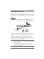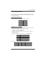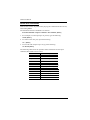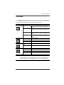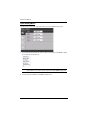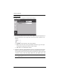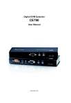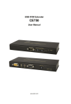
1
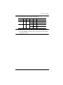
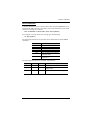
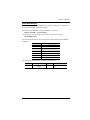
4-Port Dual View HDMI Switch VS482 User Manual www.aten.com VS482 User Manual FCC Information Federal Communication Commission Interference Statement This equipment has been tested and found to comply with the limits for a Class B digital service, pursuant to Part 15 of the FCC rules. These limits are designed to provide reasonable protection against harmful interference in a residential installation. Any changes or modifications made to this equipment may void the user’s authority to operate this equipment. This equipment generates, uses, and can radiate radio frequency energy. If not installed and used in accordance with the instructions, may cause harmful interference to radio communications. However, there is no guarantee that interference will not occur in a particular installation. If this equipment does cause harmful interference to radio or television reception, which can be determined by turning the equipment off and on, the user is encouraged to try to correct the interference by one or more of the following measures: Reorient or relocate the receiving antenna. Increase the separation between the equipment and receiver. Connect the equipment into an outlet on a circuit different from that to which the receiver is connected. Consult the dealer or an experienced radio/TV technician for help. FCC Caution: Any changes or modifications not expressly approved by the party responsible for compliance could void the user's authority to operate this equipment. RoHS This product is RoHS compliant. SJ/T 11364-2006 The following contains information that relates to China. ii VS482 User Manual User Information Online Registration Be sure to register your product at our online support center: International http://eservice.aten.com Telephone Support For telephone support, call this number: International 886-2-8692-6959 China 86-10-5255-0110 Japan 81-3-5615-5811 Korea 82-2-467-6789 North America 1-888-999-ATEN ext 4988 United Kingdom 44-8-4481-58923 User Notice All information, documentation, and specifications contained in this manual are subject to change without prior notification by the manufacturer. The manufacturer makes no representations or warranties, either expressed or implied, with respect to the contents hereof and specifically disclaims any warranties as to merchantability or fitness for any particular purpose. Any of the manufacturer's software described in this manual is sold or licensed as is. Should the programs prove defective following their purchase, the buyer (and not the manufacturer, its distributor, or its dealer), assumes the entire cost of all necessary servicing, repair and any incidental or consequential damages resulting from any defect in the software. The manufacturer of this system is not responsible for any radio and/or TV interference caused by unauthorized modifications to this device. It is the responsibility of the user to correct such interference. The manufacturer is not responsible for any damage incurred in the operation of this system if the correct operational voltage setting was not selected prior to operation. PLEASE VERIFY THAT THE VOLTAGE SETTING IS CORRECT BEFORE USE. iii VS482 User Manual Package Contents The VS482 4-Port Dual View HDMI Switch package consists of: 1 VS482 4-Port Dual View HDMI Switch 1 IR Remote Control Unit 1 Power Adapter 1 User Instructions 1 Mounting kit Check to make sure that all the components are present and that nothing got damaged in shipping. If you encounter a problem, contact your dealer. Read this manual thoroughly and follow the installation and operation procedures carefully to prevent any damage to the unit, and/or any of the devices connected to it. * Features may have been added to the VS482 since this manual was printed. Please visit our website to download the most up-to-date version. © Copyright 2011–2014 ATEN® International Co., Ltd. Manual Part No. PAPE-0347-AT2G Manual Date: 2014-05-22 ATEN and the ATEN logo are registered trademarks of ATEN International Co., Ltd. All rights reserved. All other brand names and trademarks are the registered property of their respective owners. iv VS482 User Manual Contents FCC Information . . . . . . . . . . . . . . . . . . . . . . . . . . . . . . . . . . . . . . . . . . . . . ii User Information . . . . . . . . . . . . . . . . . . . . . . . . . . . . . . . . . . . . . . . . . . . . .iii Online Registration . . . . . . . . . . . . . . . . . . . . . . . . . . . . . . . . . . . . . . . .iii Telephone Support . . . . . . . . . . . . . . . . . . . . . . . . . . . . . . . . . . . . . . . .iii User Notice . . . . . . . . . . . . . . . . . . . . . . . . . . . . . . . . . . . . . . . . . . . . . .iii Package Contents. . . . . . . . . . . . . . . . . . . . . . . . . . . . . . . . . . . . . . . . . . . iv Contents . . . . . . . . . . . . . . . . . . . . . . . . . . . . . . . . . . . . . . . . . . . . . . . . . . . v About this Manual . . . . . . . . . . . . . . . . . . . . . . . . . . . . . . . . . . . . . . . . . . . vii Conventions . . . . . . . . . . . . . . . . . . . . . . . . . . . . . . . . . . . . . . . . . . . . . . .viii Product Information. . . . . . . . . . . . . . . . . . . . . . . . . . . . . . . . . . . . . . . . . .viii 1. Introduction Overview . . . . . . . . . . . . . . . . . . . . . . . . . . . . . . . . . . . . . . . . . . . . . . . . . . . 1 Features . . . . . . . . . . . . . . . . . . . . . . . . . . . . . . . . . . . . . . . . . . . . . . . . . . . 2 Requirements . . . . . . . . . . . . . . . . . . . . . . . . . . . . . . . . . . . . . . . . . . . . . . . 3 Source Device . . . . . . . . . . . . . . . . . . . . . . . . . . . . . . . . . . . . . . . . . . . . 3 Display Device. . . . . . . . . . . . . . . . . . . . . . . . . . . . . . . . . . . . . . . . . . . . 3 Cables . . . . . . . . . . . . . . . . . . . . . . . . . . . . . . . . . . . . . . . . . . . . . . . . . . 3 Components . . . . . . . . . . . . . . . . . . . . . . . . . . . . . . . . . . . . . . . . . . . . . . . . 4 Front View . . . . . . . . . . . . . . . . . . . . . . . . . . . . . . . . . . . . . . . . . . . . . . . 4 Rear View . . . . . . . . . . . . . . . . . . . . . . . . . . . . . . . . . . . . . . . . . . . . . . . 5 IR Remote Control. . . . . . . . . . . . . . . . . . . . . . . . . . . . . . . . . . . . . . . . . 6 2. Hardware Setup Rack Mounting . . . . . . . . . . . . . . . . . . . . . . . . . . . . . . . . . . . . . . . . . . . . . . 7 Grounding . . . . . . . . . . . . . . . . . . . . . . . . . . . . . . . . . . . . . . . . . . . . . . . 8 Installation . . . . . . . . . . . . . . . . . . . . . . . . . . . . . . . . . . . . . . . . . . . . . . . . . . 9 Installing the RS-232 Controller . . . . . . . . . . . . . . . . . . . . . . . . . . . . . 10 3. Operation Overview . . . . . . . . . . . . . . . . . . . . . . . . . . . . . . . . . . . . . . . . . . . . . . . . . . 11 Manual Selection . . . . . . . . . . . . . . . . . . . . . . . . . . . . . . . . . . . . . . . . . 11 Remote Control Selection . . . . . . . . . . . . . . . . . . . . . . . . . . . . . . . . . . 11 Switch Mode . . . . . . . . . . . . . . . . . . . . . . . . . . . . . . . . . . . . . . . . . . . . . . . 12 Audio Return Channel (ARC) . . . . . . . . . . . . . . . . . . . . . . . . . . . . . . . . . . 13 Initial Setup . . . . . . . . . . . . . . . . . . . . . . . . . . . . . . . . . . . . . . . . . . . . . 13 Enabling ARC . . . . . . . . . . . . . . . . . . . . . . . . . . . . . . . . . . . . . . . . . . . 14 RS-232 Serial Interface. . . . . . . . . . . . . . . . . . . . . . . . . . . . . . . . . . . . . . . 15 Configuring the Serial Port . . . . . . . . . . . . . . . . . . . . . . . . . . . . . . . . . 15 Standby/Power Commands. . . . . . . . . . . . . . . . . . . . . . . . . . . . . . . . . 15 Switch Port Commands . . . . . . . . . . . . . . . . . . . . . . . . . . . . . . . . . . . . 16 Switch Mode Commands . . . . . . . . . . . . . . . . . . . . . . . . . . . . . . . . . . 18 EDID Commands . . . . . . . . . . . . . . . . . . . . . . . . . . . . . . . . . . . . . . . . 20 CEC Commands . . . . . . . . . . . . . . . . . . . . . . . . . . . . . . . . . . . . . . . . . 21 Mute Commands . . . . . . . . . . . . . . . . . . . . . . . . . . . . . . . . . . . . . . . . . 22 v VS482 User Manual ARC Commands . . . . . . . . . . . . . . . . . . . . . . . . . . . . . . . . . . . . . . . . . 23 Echo . . . . . . . . . . . . . . . . . . . . . . . . . . . . . . . . . . . . . . . . . . . . . . . . . . 24 Reset. . . . . . . . . . . . . . . . . . . . . . . . . . . . . . . . . . . . . . . . . . . . . . . . . . 24 Baud Rate Setting . . . . . . . . . . . . . . . . . . . . . . . . . . . . . . . . . . . . . . . . 25 Verification . . . . . . . . . . . . . . . . . . . . . . . . . . . . . . . . . . . . . . . . . . . . . 26 Powering Off and Restarting. . . . . . . . . . . . . . . . . . . . . . . . . . . . . . . . . . . 26 OSD Menu . . . . . . . . . . . . . . . . . . . . . . . . . . . . . . . . . . . . . . . . . . . . . . . . 27 Input Setting Menu . . . . . . . . . . . . . . . . . . . . . . . . . . . . . . . . . . . . . . . 28 Audio Setting. . . . . . . . . . . . . . . . . . . . . . . . . . . . . . . . . . . . . . . . . . . . 29 OSD Setting . . . . . . . . . . . . . . . . . . . . . . . . . . . . . . . . . . . . . . . . . . . . 30 System Setting . . . . . . . . . . . . . . . . . . . . . . . . . . . . . . . . . . . . . . . . . . 31 4. The Firmware Upgrade Utility Introduction . . . . . . . . . . . . . . . . . . . . . . . . . . . . . . . . . . . . . . . . . . . . . . . . 33 Downloading the Firmware Upgrade Package . . . . . . . . . . . . . . . . . . 33 Preparation . . . . . . . . . . . . . . . . . . . . . . . . . . . . . . . . . . . . . . . . . . . . . . . . 34 Starting the Upgrade. . . . . . . . . . . . . . . . . . . . . . . . . . . . . . . . . . . . . . . . . 35 Upgrade Succeeded . . . . . . . . . . . . . . . . . . . . . . . . . . . . . . . . . . . . . . . . . 37 Upgrade Failed . . . . . . . . . . . . . . . . . . . . . . . . . . . . . . . . . . . . . . . . . . . . . 37 Firmware Upgrade Recovery . . . . . . . . . . . . . . . . . . . . . . . . . . . . . . . . . . 38 Appendix Safety Instructions . . . . . . . . . . . . . . . . . . . . . . . . . . . . . . . . . . . . . . . . . . 39 General . . . . . . . . . . . . . . . . . . . . . . . . . . . . . . . . . . . . . . . . . . . . . . . . 39 Rack Mounting . . . . . . . . . . . . . . . . . . . . . . . . . . . . . . . . . . . . . . . . . . 41 Technical Support. . . . . . . . . . . . . . . . . . . . . . . . . . . . . . . . . . . . . . . . . . . 42 International . . . . . . . . . . . . . . . . . . . . . . . . . . . . . . . . . . . . . . . . . . . . 42 North America . . . . . . . . . . . . . . . . . . . . . . . . . . . . . . . . . . . . . . . . . . . 42 Specifications . . . . . . . . . . . . . . . . . . . . . . . . . . . . . . . . . . . . . . . . . . . . . . 43 Limited Warranty. . . . . . . . . . . . . . . . . . . . . . . . . . . . . . . . . . . . . . . . . . . . 44 vi VS482 User Manual About this Manual This User Manual is provided to help you get the most from your VS482 system. It covers all aspects of installation, configuration and operation. An overview of the information found in the manual is provided below. Introduction, introduces you to the VS482 system. Its purpose, features and benefits are presented, and its front and back panel components are described. Hardware Setup, describes how to set up your VS482 installation. The necessary steps are provided. Operation, explains the fundamental concepts involved in operating the VS482 via the front panel pushbuttons, remote controlled On-Screen Display (OSD), or through the RS-232 serial interface. The Firmware Upgrade Utility, explains how to download the VS482’s firmware and upgrade the device using the utility. An Appendix, provides specifications and other technical information regarding the VS482. vii VS482 User Manual Conventions This manual uses the following conventions: Monospaced Indicates text that you should key in. [] Indicates keys you should press. For example, [Enter] means to press the Enter key. If keys need to be chorded, they appear together in the same bracket with a plus sign between them: [Ctrl+Alt]. 1. Numbered lists represent procedures with sequential steps. ♦ Bullet lists provide information, but do not involve sequential steps. → Indicates selecting the option (on a menu or dialog box, for example), that comes next. For example, Start → Run means to open the Start menu, and then select Run. Indicates critical information. Product Information For information about all ATEN products and how they can help you connect without limits, visit ATEN on the Web or contact an ATEN Authorized Reseller. Visit ATEN on the Web for a list of locations and telephone numbers: International http://www.aten.com North America http://www.aten-usa.com viii Chapter 1 Introduction Overview With more and more HDMI devices entering the Home Theater market, the need for simultaneous access to different HDMI sources is becoming increasingly important. Now, the VS482 4-Port Dual View HDMI Switch offers an easy and affordable way to add HDMI capabilities to your home theater system by allowing you to switch easily between up to four HDMI sources that are connected to up to two HDMI displays. The VS482 supports four HDMI input sources and two HDMI output displays. It is designed for two HDTV, audio/video receiver (AVR) or HD projector display applications. The VS482 complies with HDMI standards, and is designed to support 3D content, as well as featuring Audio Return Channel (ARC) functionality. The VS482 also offers fast switching and has OSD display controls for video, audio, system configuration and information. With four HDMI input ports, the VS482 allows you to connect four HDMI devices (such as an HD camcorder, satellite box, HD-DVD player, hi-def Bluray player, home theater PC, stand-alone streaming media player, or gaming console) to two HDMI monitors, displays, projectors or TVs at the same time. The remote control and convenient front panel pushbuttons allow you to quickly and easily toggle between HDMI sources, while the front panel LEDs indicate the source device at a glance. Furthermore, for complete system and install integration, RS-232 control is standard through the VS482’s built-in bi-directional RS-232 serial remote port that allows the switch to be controlled through a Control Unit, PC, and/or home automation / home theater software package. 1 VS482 User Manual Features Allows up to four HDMI sources to be connected to two HDMI displays Easy and affordable way to add four HDMI inputs to your home theater system HDCP 1.2 compatible Supports HDMI (3D, Audio Return Channel and deep color) Audio Return Channel (ARC) function – connect an HDMI cable to the ARC port to send audio from your source device to your audio/video receiver Instant switching between HDMI input sources via front panel pushbuttons or through the RS-232 serial control port Features EDID Expert technology to set up different configurations via different EDID modes Allows users to view the HDMI input source port/device for easy selection On-Screen Display (OSD) for system configuration settings and information display Built-in bi-directional RS-232 serial control port for high-end system control Note: The AP and GUI operation instructions can be downloaded from the ATEN website (www.aten.com). IR control signal extension – extend the reach of the IR controller by adding an IR receiver unit (IR receiver can be purchased separately) Consumer Electronics Control (CEC) allows interconnected HDMI devices to communicate and respond to one remote control Superior video quality – HDTV resolutions of 480p, 720p, 1080i, 1080p (1920x1080); VGA, SVGA, SXGA, UXGA, and WUXGA (1920 x 1200) Supports multi-channel audio 2/5.1/ 7.1 Extracts audio from HDMI input signal that supports both optical and coaxial digital audio and one stereo audio output Rack mountable, all-metal casing Plug-and-play – no software installation required DDC compatible LED indication of HDMI source devices 2 Chapter 1. Introduction Requirements The following equipment is required for a complete VS482 installation: Source Device HDMI Type A output connector(s) Note: A DVI/HDMI adapter is required when connecting a DVI source device. Display Device Up to 2 display devices or receivers with an HDMI Type A input connector Cables 4 HDMI cables Note: 1. No cables are included in this package. We strongly recommend that you purchase high-quality cables of appropriate length since this will affect the quality of the audio and video display. Contact your dealer to purchase the correct cable sets. 2. If you wish to utilize the VS482’s high-end serial controller function, you will also need to purchase an appropriate RS-232 cable. See Installing the RS-232 Controller, page 10. 3 VS482 User Manual Components Front View 1 2 34 5 7 6 No. Component Description 1 Port LEDs The SELECTED port’s LED (bottom, green) lights up to indicate that the port is selected. 2 ARC LED The LED (blue) lights up when the ARC function is enabled. 3 Power Pushbutton Press this button to turn on / off the switch. 4 Power LED The LED (green) lights up when the switch is powered on. The LED (orange) lights up to indicate that the switch is in standby mode. 4 5 IR Receiver This receives signals from the IR remote control. 6 Port Selection Pushbuttons Pressing a port selection pushbutton routes the A/V source from the corresponding input port to the output port for display. 7 ARC button Press this button to enable / disable the ARC function. Chapter 1. Introduction Rear View 1 No. 1 2 3 4 5 6 7 Component Grounding Terminal 8 9 Description The grounding wire (used to ground the unit) attaches here. Note: The grounding wire is not included in this package. Contact your dealer for more information. 2 Power Jack The power adapter cable plugs in here. 3 IR Extender Port Connect the IR Extender to this port. Note: The additional IR receiver can be purchased separately. 4 RS-232 Serial Port This is the serial remote port for input source selection and high-end system control, including firmware upgrade. 5 Stereo Audio Ports The red port is for the right audio channel, and the white port is for the left audio channel. 6 Digital Audio Ports Connect the optical and coaxial audio cables to these ports. 7 HDMI Out (port 2) The cable from the HDMI display or receiver device plugs in here. 8 HDMI Out (port 1) The cable from the HDMI display device or receiver (ARC In) plugs in here. Connect the ARC audio input connector or receiver to this port. The ARC audio can be transmitted back (to audio receivers) through this connectivity 9 HDMI In The cables from the HDMI source devices can plug into any of four available ports. 5 VS482 User Manual IR Remote Control 1 2 3 4 5 6 9 7 8 No. 6 Component Description 1 Up / Down / Left / Right Buttons Press the Up / Down / Left / Right button to cycle through the OSD menu/selection. 2 Setup Press this to confirm the selection on the OSD screen. 3 On Press this to power on the display. 4 Off Press this to power off the display. 5 Port Selection Buttons Press a button to bring the focus directly to the source 1~4 device attached to its associated port. 6 Menu Press this to enable / disable the OSD menu. 7 Info button Press this button to display information about the source device on the upper left side of the screen. The information can include: Source port number; Source port number + Source Type; or turned off. 8 ARC Enable / Disable ARC function. See ARC Commands, page 23. 9 HDMI Mute Enable / Disable audio for the output HDMI port. See Switch Mode, page 12. Chapter 2 Hardware Setup 1. Important safety information regarding the placement of this device is provided on page 39. Please review it before proceeding. 2. Make sure that the power to all devices connected to the installation are turned off. 3. Make sure that all devices you will be installing are properly grounded. Rack Mounting For convenience and flexibility, the VS482 can be mounted on system racks. To rack mount a unit do the following: 1. Using the screws provided in the Mounting Kit, screw the mounting bracket into the side of the unit as show in the diagram below: Phillips hex head M3x8 7 VS482 User Manual 2. Screw the bracket into any convenient location on the rack. Note: These screws are not provided. We recommend that you use M5 x 12 Phillips Type I cross, recessed type screws. Grounding To prevent damage to your installation it is important that all devices are properly grounded. 1. Use a grounding wire to ground the VS482 by connecting one end of the wire to the grounding terminal, and the other end of the wire to a suitable grounded object. 2. Make sure that the computer(s)/device(s) that the VS482 connects to are properly grounded. 8 Chapter 2. Hardware Setup Installation Installation of the VS482 is simply a matter of plugging in the appropriate cables. To install the switch, refer to the installation diagram below as you perform the following steps: 1. Use an HDMI cable to connect the HDMI input port on the video display device to the HDMI output port on the rear of the VS482. 2. Use HDMI cables to connect the HDMI output ports on the source device(s) to the HDMI input ports on the VS482. 3. Plug the provided power adapter into an appropriate AC power source; plug the power adapter cable into the Power Jack on the VS482. 4. Connect your audio devices (such as speakers or AVRs) to the Stereo Audio Ports or Digital Audio Ports. 5. (Optional) To edit the VS482 system settings through the RS-232 port, connect the hardware / software controller here. Hardware / Software Controller 3 5 4 1 AVR HDMI Output Device 2 HDMI A/V Source Devices This completes the basic installation of the 4-Port Dual View HDMI Switch. You may now power on the display and source devices. 9 VS482 User Manual Installing the RS-232 Controller In order to use the RS-232 serial interface to attach a high-end controller (such as a PC) to the VS482, use a serial cable such as a modem cable. The end connecting to the VS482 should have a 9-pin male connector. Connect this to the serial interface on the rear of the VS482. Refer to number 5 on the previous diagram. Note: To configure the controller serial port, see page 15. 10 Chapter 3 Operation Overview The 4-Port Dual View HDMI Switch offers easy and flexible source device selection with either the front panel pushbuttons, with the remote control, or through the RS-232 serial interface. Note: 1. Whenever the VS482 is powered on and there is no video input source connected, it automatically selects Port 1 as the active port (i.e., the Port 1 LED lights up). You may choose one of the methods outlined below to select a different port as your active port. 2. The VS482 takes about 10-20 seconds to boot up the system and apply the system configuration when first powered on. Manual Selection To select a source device, press the pushbutton that corresponds to the port to which it is connected. Note: The Port LED (green) light indicates which port is currently selected. Remote Control Selection To select a source device with the remote control, press the number button that corresponds to the port to which it is connected. See IR Remote Control, page 6 for more details. Note: Aim the remote control unit at the IR receiver located on the front panel of the VS482. For optimum performance, make sure there is a clear lineof-sight between the remote control unit and the IR receiver. 11 VS482 User Manual Switch Mode You can choose how the VS482 behaves when a new input source is connected. There are three Switch Modes as follows: Default – The switch behaves normally without automatic switching operation. Next – Switch priority is placed on the next port that has a new source connected to it (default). Auto – Places priority on a selected port so that when a source is connected to the said port, the VS482 automatically switches to it, and the port can not be changed until the source is unplugged or auto switching is disabled. In addition, the Go To function, which can be turned On or Off via RS-232 commands, enables the VS482 to switch to the next port with a powered on source device when the current input source is off. Refer to Switch Mode Commands, page 18 for more details. 12 Chapter 3. Operation Audio Return Channel (ARC) Audio Return Channel (ARC) allows an HDMI source device that receives content via air waves (such as a TV or STB connected to a satellite antenna) to send audio “upstream” to your HDMI display devices using only one HDMI cable. Initial Setup The VS482 supports dual HDMI output for dual view, such as two HDTV or audio/video receiver (AVR) applications, as shown in the following diagram. HDMI Sources or AVR Audio Output or AVR HDMI Displays The audio/video coming from the HDMI sources (Blu-ray, DVD, etc.) are received by the VS482 and then passed on to the HDMI displays (TV, projector or AVR). However if the HDMI audio or video is coming from the TV (through a satellite antenna or STB), you can enable ARC so that audio is sent to the AVR/ HDMI receiver through the HDMI cable or the device(s) connected to the audio output port(s). See p. 14 for the diagram. Note: 1. Without ARC, you must connect another cable, specifically for passing audio, from the TV to the AVR or the device(s) connected to the audio output port(s). 2. The ARC function requires HDTV built-in ARC function and connect to the correct HDMI output port. Check your HDTV’s user manual for this information. 13 VS482 User Manual Enabling ARC With ARC enabled, the TV can act as the HDMI source and send audio “upstream” to the AVR or speakers connected to the HDMI output ports of the VS482. Note: The HDMI output port 1 is also the ARC input port, depending on whether the ARC feature is enabled or disabled. See ARC Commands, page 23 for more information. In the following diagram, audio from the TV goes to the VS482 through the ARC Input port, and is then passed on to the AVR via the HDMI cable or the audio devices connected to the HDMI output ports. A user can also connect to an audio device (receiver) using an optical or coaxial audio connector. ARC input port Satellite STB etc. Audio output AVR Audio/Video Receiver (HDMI output port 2) No need for another cable for audio Note: 1. The scenario above works only if the TV supports HDMI and have ARC enabled. 2. The ARC LED (blue) lights up to indicate that the ARC function is enabled. There is no audio output if your HDTV does not support ARC function or if the ARC function is not enabled. 14 Chapter 3. Operation RS-232 Serial Interface The VS482’s built-in bi-directional RS-232 serial interface allows system control through a high-end controller, PC, and/or home automation / home theater software package. Configuring the Serial Port The controller’s serial port should be configured as follows: Baud Rate 19200 Data Bits 8 Parity None Stop Bits 1 Flow Control None Standby/Power Commands The Standby/Power feature enables the VS482 to enter power saving mode. The formula for Standby/Power commands is as follows: Standby + Control command [Enter] For example, to disable the Standby/Power feature, input the following: standby off [Enter] The following tables show the possible values for the Control string: Command Description standby Standby/Power command Control Description on Turn on power saving mode off Turn off power saving mode The following table shows the available command list: Command Control Enter Description standby on [Enter] Power saving mode on standby off [Enter] Power saving mode off 15 VS482 User Manual Switch Port Commands These actions can also be performed by keying the command into the text box, and clicking Send. The formula for Switch commands is as follows: Switch Command + Input Command + Port number [Enter] 1. For example, to switch input port to port 02, type the following: sw i02 [Enter] 2. To switch to the next port, input the following: sw + [Enter] 3. To turn off video output on port 03, type the following: sw o03 off [Enter] The following tables show the possible values and formats for the Input command, Port Number and Control: Command sw Description Switch command Input Command i Description Input command Port number xx Description 01-04 port (default is 01) Control 16 Description on Turn on the display off Turn off the display + Next Port - Previous Port Chapter 3. Operation The following table shows the available command list: Command Input sw sw sw i Port Control xx Enter Description [Enter] Switch Input Port on [Enter] Turn on (Display out) off [Enter] Turn off (No output) + [Enter] Switch to the next input - [Enter] Switch to the previous input Note: 1. Each command string can be separated with a space. 2. The Port Number command string can be skipped, and the default value will be used. 17 VS482 User Manual Switch Mode Commands See Switch Mode, page 12 for more information about the Switch Mode feature. In addition, the Go To function enables the VS482 to switch to the next port with a powered on source device when the current input source is off. The formula for Switch Mode commands is as follows: Switch Command + Input Command + Port Number + Control + [Enter] 1. For example, to enable auto switching for port 02, type the following: swmode i02 auto [Enter] 2. To enable the auto switch next mode, type the following: swmode next [Enter] 3. To turn auto switching off, type the following: swmode default [Enter] 4. To enable the Go To function, type the following: swmode goto on [Enter] 18 Chapter 3. Operation The following tables show the possible values and formats for the Input command, Port Number and Control: Command swmode Description Switch Mode command Input Command i Description Input command Port number xx Description 01-04 port (default is 01) Control Description default No automatic switching operation next Priority is placed on the next port that has a new source connected to it (default) auto Priority is placed on a selected port goto on Switch to the next port with a powered on source device when the current input source is off goto off Disable Go To function The following table shows the available command list: Command Input swmode swmode i Port Control Enter Description xx default [Enter] Use Default switch mode next [Enter] Use Next switch mode auto [Enter] Use Auto switch mode goto on [Enter] Enable Go To function goto off [Enter] Disable Go To function 19 VS482 User Manual EDID Commands Extended Display Identification Data (EDID) is a data format that contains a display's basic information and is used to communicate with the video source/ system. You can set up which EDID mode the VS482 uses with the following command: EDID Command + Control (port1 / auto / default) [Enter] For example, to use the Port1 EDID setting, type the following: edid port1 [enter] The following tables show the possible values and formats for the Control command: Command edid Description Enable EDID selection Control Description port1 Implement the EDID of the connected display to Port 1, and pass it to the video source auto Implement the EDID of all connected displays. The VS482 uses the best resolution for all displays (default). default Implements ATEN’s default EDID The following table shows the available command list: 20 Command Control Enter Description edid port1 [Enter] The EDID from Port 1 is passed to the video source edid auto [Enter] The VS482 implements the EDID of all connected displays and uses the best resolution for all displays (default) edid default [Enter] ATEN’s default EDID is passed to the video source Chapter 3. Operation CEC Commands Consumer Electronics Control (CEC) allows interconnected HDMI devices to communicate and respond to one remote control. The formula for CEC mode selection commands is as follows: CEC Command + Control (Off / Auto / Port1) [Enter] For example, to use the Port1 CEC setting, type the following: cec port1 [enter] The following tables show the possible values and formats for the Control command: Command cec Description Enable CEC selection Control off Description Disable CEC (default) auto Apply the video source’s CEC to all display output port1 Apply the video source’s CEC only to port 1 The following table shows the available command list: Command Control Enter Description cec off [Enter] CEC off (default) cec auto [Enter] Connect the video source’s CEC with all display output cec port1 [Enter] Apply the video source’s CEC only to port 1 21 VS482 User Manual Mute Commands Enable or disable audio coming from the output port(s) using the following command: Mute Command + Control (On / Off) [Enter] For example, to mute the audio, type the following: mute on [enter] The following tables show the possible values and formats for the Control command: Command mute Description Enable / Disable audio of HDMI output port Control Description on Mute on; audio from HDMI output port is disabled off Mute off; audio output enabled (default) Note: Each command string can be separated with a space. The following table shows the available command list: Command 22 Control Enter Description mute on [Enter] Mute on (no audio) mute off [Enter] Mute off (audio out) Chapter 3. Operation ARC Commands Audio Return Channel (ARC) allows a source device (TV, STB, etc.) to send audio “upstream” to an audio/video receiver using only one HDMI cable. The formula for enabling/disabling ARC is as follows: ARC Command + Control (On / Off) [Enter] For example, to enable ARC, type the following: arc on [enter] The following tables show the possible values and formats for the Control command: Command arc Description Enable / Disable ARC Control Description on ARC on; output audio passes from HDMI output port 1 to HDMI output port off ARC is disabled (default) The following table shows the available command list: Command Control Enter Description arc on [Enter] ARC on arc off [Enter] ARC off 23 VS482 User Manual Echo The Echo function lets the VS482 perform front panel and IR control operations, but not commands received through the RS-232 interface. The formula for the Echo command is as follows: Echo Command + Control (on/off) + [Enter] For example, to enable the Echo function, type the following: echo on [enter] The following tables show the possible values and formats for the Control command: Command Description echo Enable / Disable Echo function Control Description on Echo function on off Echo function off (default) The following table shows the available command list: Command Control Enter Description echo on [Enter] Echo on echo off [Enter] Echo off Reset You can reset the VS482to default factory settings. The formula for the Reset command is as follows: Reset Command [Enter] The following tables show the possible values and formats for the Control command: Command reset Description Reset the device settings The following table shows the available command list: 24 Command Enter reset [Enter] Description Reset the device settings Chapter 3. Operation Baud Rate Setting You can select the RS-232 Baud Rate you want the VS482 to use. Options are 9600, 19200 (default) 38400 and 115200. The formula for Baud Rate setting command is as follows: Baud Command + Control [Enter] For example, to select 38400 as your baud rate, type the following: baud 38400 [enter] The following tables show the possible values and formats for the Control command: Command baud Description Sets the RS-232 baud rate Control Description 9600 Use 9600 baud rate 19200 Use 19200 baud rate 38400 Use 38400 baud rate 115200 Use 115200 baud rate The following table shows the available command list: Command Control Enter baud 9600 / 19200 / 38400 / 115200 [Enter] Description Sets the RS-232 baud rate 25 VS482 User Manual Verification After entering a command, a verification message appears at the end of the command line as follows: Command OK - indicates that the command is correct and successfully performed by the switch Command incorrect - indicates that the command has the wrong format and/or values. Powering Off and Restarting If you power off the VS482, follows these steps before powering it on again: 1. Power off the attached devices. 2. Unplug the power adapter cable from the VS482. 3. Wait 10 seconds, and then plug the power adapter cable back in. 4. After the VS482 is powered on, power on the attached devices. 26 Chapter 3. Operation OSD Menu Use the MENU pushbutton on the remote control to view the OSD menu and cycle through the options in the order shown in the table below. See IR Remote Control, page 6 for details on how to use the remote control. Menu Page Input Setting Audio Setting OSD Setting Sub-Menu Page(s) HDMI 1 HDMI device / Blu-ray player / DVD player / Game Console / Set Top Box / Portable Device / PC HDMI 2 HDMI device / Blu-ray player / DVD player / Game Console / Set Top Box / Portable Device / PC HDMI 3 HDMI device / Blu-ray player / DVD player / Game Console / Set Top Box / Portable Device / PC HDMI 4 HDMI device / Blu-ray player / DVD player / Game Console / Set Top Box / Portable Device / PC ARC Disable / Enable Audio Channel AUTO / Stereo / 5.1 Channel / 7.1 Channel HDMI Audio Output On / Off Message Display Mode Channel / Full / Off Transparency 0 ~100 (default is 75) System Setting EDID Auto / Port1 / Default CEC Off / Auto / Port1 Reset to Default On / Off Version Version Number Note: 1. The highlighted texts indicate the VS482’s default setting. 2. The OSD function is disabled while 3D content is being displayed. Switch to 2D content or a different input port to enable the OSD. 27 VS482 User Manual Input Setting Menu Use this screen to select the video source device(s) for the HDMI input port(s). 1. Use the drop-down menu to select a video source device for HDMI 1 input port. Options are as follows. Note: The default value HDMI Device does not point to any device. It means there is no video source selected for that HDMI input port. 2. Do the same for HDMI 2 to HDMI 4 input ports. 28 Chapter 3. Operation Audio Setting Use this screen to configure the VS482 audio settings. 1. Use the drop-down menu to Enable or Disable ARC on the VS482. See Audio Return Channel (ARC), page 13 for more details on this feature. 2. Use the drop-down menu to select which audio channel receiver the VS482 uses. The default value is Auto. 3. Use the drop-down menu to turn on/off the audio coming from the HDMI output port(s). Select On to enable audio from the active HDMI output port, and select Off to disable it. 29 VS482 User Manual OSD Setting Use this screen to configure the VS482 OSD settings. 1. Use the drop-down menu to select which display mode the VS482 uses to display information in the upper left corner of the screen. Options are as follows. Channel - This shows the source port number. Full - This shows the source port number and source type. See Input Setting Menu, page 28 for the list of source types. Off - There is no information shown. 2. Select the visibility of the OSD menu when it is invoked. Press the menu button to enter the adjustment menu. Press the up/down button to select increase/decrease the value then press the setup button to adjust. The value 100 shows a fully visible and opaque OSD menu. The default value is 75. Note: The Transparency value must be divisible by 5 (i.e., 5, 10, 15, 20... and so on). 30 Chapter 3. Operation System Setting Use this screen to configure the VS482 system settings. 1. Use the drop-down menu to set up which EDID mode the VS482 uses. See Verification, page 26 for more details. 2. Use the drop-down menu to select how the video source’s CEC is applied. See Verification, page 26 for more details. 3. Set this to On to have the VS482 return to default settings when it is reset. Otherwise, select Off. 4. This read-only field shows the firmware version of the VS482. 31 VS482 User Manual This Page Intentionally Left Blank 32 Chapter 4 The Firmware Upgrade Utility Introduction The purpose of the Windows-based Firmware Upgrade Utility is to provide an easy process for upgrading the VS482. The program comes as part of a Firmware Upgrade Package that is specific for each device. As new firmware versions become available, new firmware upgrade packages are posted on our website. Check the website regularly to find the latest information and packages. Downloading the Firmware Upgrade Package To download the firmware upgrade package: 1. On our Website go to: Download - Firmware and choose the device model, or from the VS482 product page under the Resources tab, select Firmware. A list of available firmware upgrade packages appears. 2. Choose the firmware upgrade package that you wish to install (usually the most recent) and download it to your computer. 33 VS482 User Manual Preparation To prepare for the firmware upgrade, do the following: 1. Use an RS-232 cable to connect a COM port on your computer to the RS232 Serial Port of your VS482. 2. Unplug the VS482’s power adapter. 3. Hold-down front panel pushbutton 1 and plug the power adapter into the VS482 to power the unit. 4. If successful, the port 1 LED will start flashing and you can start the upgrade process as explained on the next page. 34 Chapter 4. The Firmware Upgrade Utility Starting the Upgrade To upgrade the firmware: 1. Run the downloaded firmware upgrade package file either by doubleclicking the file icon, or by opening a command line and entering the full path to it. The Firmware Upgrade Utility welcome screen appears: Note: The screens shown in this section are for reference only. The wording and layout of the actual screens put up by the Firmware Upgrade Utility may vary slightly from these examples. 2. Read and Agree to the License Agreement (click the I Agree radio button). (Continues on next page.) 35 VS482 User Manual (Continued from previous page.) 3. Click Next to continue. The Firmware Upgrade Utility main screen appears. The devices capable of being upgraded are listed in the Device List panel: 4. Click Next to perform the upgrade. The Port LEDs 1, 3, and 4 will flash while the upgrade is in process. If you enabled Check Firmware Version, the Utility compares the device's firmware level with that of the upgrade files. If it finds that the device's version is higher than the upgrade version, it brings up a dialog box informing you of the situation and gives you the option to continue or cancel. If you didn't enable Check Firmware Version, the Utility installs the upgrade files without checking whether they are a higher level, or not. Status messages appear in the Status Messages panel, and the progress toward completion is shown on the Progress bar. 36 Chapter 4. The Firmware Upgrade Utility Upgrade Succeeded After the upgrade has completed, all port LEDs will stop flashing and a screen appears to inform you that the procedure was successful: Click Finish to close the Firmware Upgrade Utility. Upgrade Failed If the Upgrade Succeeded screen doesn't appear, it means that the upgrade failed to complete successfully. See the next section, Firmware Upgrade Recovery, for how to proceed. 37 VS482 User Manual Firmware Upgrade Recovery There are three conditions that call for firmware upgrade recovery: When a firmware upgrade is manually aborted. When the mainboard firmware upgrade fails. When the I/O firmware upgrade fails. To perform a firmware upgrade recovery, do the following: 1. Power off the device. 2. Connect the RS-232 cable to the RS-232 Serial Port. 3. Repeat the upgrade procedure. 38 Appendix Safety Instructions General Read all of these instructions. Save them for future reference. Follow all warnings and instructions marked on the device. This product is for indoor use only. Do not place the device on any unstable surface (cart, stand, table, etc.). If the device falls, serious damage will result. Do not use the device near water. Do not place the device near, or over, radiators or heat registers. The device cabinet is provided with slots and openings to allow for adequate ventilation. To ensure reliable operation, and to protect against overheating, these openings must never be blocked or covered. The device should never be placed on a soft surface (bed, sofa, rug, etc.) as this will block its ventilation openings. Likewise, the device should not be placed in a built in enclosure unless adequate ventilation has been provided. Never spill liquid of any kind on the device. Unplug the device from the wall outlet before cleaning. Do not use liquid or aerosol cleaners. Use a damp cloth for cleaning. The device should be operated from the type of power source indicated on the marking label. If you are not sure of the type of power available, consult your dealer or local power company. The device is designed for IT power distribution systems with 230V phase-to-phase voltage. To prevent damage to your installation it is important that all devices are properly grounded. The device is equipped with a DC adapter. This is a safety feature. To help protect your system from sudden, transient increases and decreases in electrical power, use a surge suppressor, line conditioner, or un-interruptible power supply (UPS). Position system cables and power cables carefully; Be sure that nothing rests on any cables. 39 VS482 User Manual Never push objects of any kind into or through cabinet slots. They may touch dangerous voltage points or short out parts resulting in a risk of fire or electrical shock. Do not attempt to service the device yourself. Refer all servicing to qualified service personnel. If the following conditions occur, unplug the device from the wall outlet and bring it to qualified service personnel for repair. Liquid has been spilled into the device. The device has been exposed to rain or water. The device has been dropped, or the cabinet has been damaged. The device exhibits a distinct change in performance, indicating a need for service. The device does not operate normally when the operating instructions are followed. Only adjust those controls that are covered in the operating instructions. Improper adjustment of other controls may result in damage that will require extensive work by a qualified technician to repair. 40 Appendix Rack Mounting Before working on the rack, make sure that the stabilizers are secured to the rack, extended to the floor, and that the full weight of the rack rests on the floor. Install front and side stabilizers on a single rack or front stabilizers for joined multiple racks before working on the rack. Always load the rack from the bottom up, and load the heaviest item in the rack first. Make sure that the rack is level and stable before extending a device from the rack. Use caution when pressing the device rail release latches and sliding a device into or out of a rack; the slide rails can pinch your fingers. After a device is inserted into the rack, carefully extend the rail into a locking position, and then slide the device into the rack. Do not overload the AC supply branch circuit that provides power to the rack. The total rack load should not exceed 80 percent of the branch circuit rating. Make sure that all equipment used on the rack – including power strips and other electrical connectors – is properly grounded. Ensure that proper airflow is provided to devices in the rack. Ensure that the operating ambient temperature of the rack environment does not exceed the maximum ambient temperature specified for the equipment by the manufacturer. Do not step on or stand on any device when servicing other devices in a rack. 41 VS482 User Manual Technical Support International For online technical support – including troubleshooting, documentation, and software updates: http://eservice.aten.com For telephone support, see Telephone Support, page iii: North America Email Support Online Technical Support [email protected] Troubleshooting Documentation Software Updates Telephone Support http://www.aten-usa.com/support 1-888-999-ATEN ext 4988 When you contact us, please have the following information ready beforehand: Product model number, serial number, and date of purchase. Your computer configuration, including operating system, revision level, expansion cards, and software. Any error messages displayed at the time the error occurred. The sequence of operations that led up to the error. Any other information you feel may be of help. 42 Appendix Specifications Function VS482 Display Connections Connectors 2 Device HDMI In 4 x HDMI Type A Female (Black) Display HDMI Out 2 x HDMI Type A Female (Black) Optical Audio Coaxial Audio 1 x RCA (Orange) Stereo Audio 2 x RCA (Red / White) RS-232 Port 1 x DB-9 Female (Black) Power IR Extension Port Switches LEDs 1 x 3.5mm phone jack 4 ARC Selection 1 Power Button 1 Selected Power IR Control 4 (Green) 1 (Blue) 1 (Green / Orange) 1 Video HDTV resolutions of 480p, 720p, 1080i, 1080p (1920x1080); WUXGA (1920 x 1200) Power Consumption Operating Temp. Storage Temp. Physical Properties 1 x DC Jack Port Switch ARC Selected Environment 1 x Toslink (Black) DC 5.3V, 6.95W 0–50ºC -20–60ºC Humidity 0–80% RH, Non-condensing Housing Metal Weight Dimensions 2.16 Kg 43.72 x 15.86 x 5.54 cm (L x W x H) 43 VS482 User Manual Limited Warranty IN NO EVENT SHALL THE DIRECT VENDOR'S LIABILITY EXCEED THE PRICE PAID FOR THE PRODUCT FROM DIRECT, INDIRECT, SPECIAL, INCIDENTAL, OR CONSEQUENTIAL DAMAGES RESULTING FROM THE USE OF THE PRODUCT, DISK, OR ITS DOCUMENTATION. The direct vendor makes no warranty or representation, expressed, implied, or statutory with respect to the contents or use of this documentation, and especially disclaims its quality, performance, merchantability, or fitness for any particular purpose. The direct vendor also reserves the right to revise or update the device or documentation without obligation to notify any individual or entity of such revisions, or update. For further inquiries, please contact your direct vendor. 44